EP1106490A2 - Cabine pour le traitement de carrosseries de vehicules - Google Patents
Cabine pour le traitement de carrosseries de vehicules Download PDFInfo
- Publication number
- EP1106490A2 EP1106490A2 EP00125461A EP00125461A EP1106490A2 EP 1106490 A2 EP1106490 A2 EP 1106490A2 EP 00125461 A EP00125461 A EP 00125461A EP 00125461 A EP00125461 A EP 00125461A EP 1106490 A2 EP1106490 A2 EP 1106490A2
- Authority
- EP
- European Patent Office
- Prior art keywords
- roof
- tunnel
- vehicle bodies
- area
- cabin
- Prior art date
- Legal status (The legal status is an assumption and is not a legal conclusion. Google has not performed a legal analysis and makes no representation as to the accuracy of the status listed.)
- Withdrawn
Links
- 238000004381 surface treatment Methods 0.000 title claims abstract description 11
- 238000007689 inspection Methods 0.000 claims description 6
- 230000003014 reinforcing effect Effects 0.000 claims description 4
- 239000002184 metal Substances 0.000 description 21
- 239000007921 spray Substances 0.000 description 11
- 238000009413 insulation Methods 0.000 description 8
- 238000003466 welding Methods 0.000 description 8
- 229910000831 Steel Inorganic materials 0.000 description 7
- 238000010276 construction Methods 0.000 description 7
- 238000009434 installation Methods 0.000 description 7
- 239000010959 steel Substances 0.000 description 7
- 239000000725 suspension Substances 0.000 description 7
- 238000004140 cleaning Methods 0.000 description 6
- 230000009189 diving Effects 0.000 description 5
- 239000011490 mineral wool Substances 0.000 description 4
- 238000002203 pretreatment Methods 0.000 description 4
- 238000004519 manufacturing process Methods 0.000 description 3
- 239000003973 paint Substances 0.000 description 3
- 241000282346 Meles meles Species 0.000 description 2
- 238000009833 condensation Methods 0.000 description 2
- 230000005494 condensation Effects 0.000 description 2
- 238000003618 dip coating Methods 0.000 description 2
- 239000000428 dust Substances 0.000 description 2
- 230000003670 easy-to-clean Effects 0.000 description 2
- 238000007654 immersion Methods 0.000 description 2
- 239000007788 liquid Substances 0.000 description 2
- 239000000463 material Substances 0.000 description 2
- 239000002245 particle Substances 0.000 description 2
- 230000000712 assembly Effects 0.000 description 1
- 238000000429 assembly Methods 0.000 description 1
- 239000000969 carrier Substances 0.000 description 1
- 238000010516 chain-walking reaction Methods 0.000 description 1
- 238000005520 cutting process Methods 0.000 description 1
- 230000002349 favourable effect Effects 0.000 description 1
- 238000012423 maintenance Methods 0.000 description 1
- 239000003595 mist Substances 0.000 description 1
- 230000002787 reinforcement Effects 0.000 description 1
- 238000011144 upstream manufacturing Methods 0.000 description 1
Images





Classifications
-
- B—PERFORMING OPERATIONS; TRANSPORTING
- B62—LAND VEHICLES FOR TRAVELLING OTHERWISE THAN ON RAILS
- B62D—MOTOR VEHICLES; TRAILERS
- B62D65/00—Designing, manufacturing, e.g. assembling, facilitating disassembly, or structurally modifying motor vehicles or trailers, not otherwise provided for
- B62D65/02—Joining sub-units or components to, or positioning sub-units or components with respect to, body shell or other sub-units or components
- B62D65/18—Transportation, conveyor or haulage systems specially adapted for motor vehicle or trailer assembly lines
Definitions
- the present invention relates to a cabin for surface treatment of vehicle bodies that have a tunnel and a conveyor device for conveying the vehicle bodies through the tunnel, which one above the Includes vehicle means running conveying means, the tunnel being over the track of the vehicle bodies through the tunnel arranged roof, which one Roof area inclined to the horizontal, which the Track the vehicle bodies throughout the cabin Width covered.
- such cabins of the type mentioned are known in which the funding is double-stranded, whereby each strand through a side next to and above the web the conveyor chain running along the vehicle bodies is formed, and where the roof of the tunnel is designed as a pointed roof which is the path of the vehicle bodies through the cabin and the conveyor chains as well as the management of the conveyor chains serving chain guideways and the suspension of the Chain guideways covered.
- the design of the canopy as a pointed roof prevents that condensing at the bottom of the canopy Wet medium from above onto those conveyed through the cabin Vehicle bodies are dripping down.
- Such a condensation of wet medium on the bottom of the roof can occur especially when the vehicle bodies - for example for cleaning purposes - with Wet medium with a higher temperature than the ambient temperature (for example 60 ° C) are cleaned. Vapor-shaped Wet medium can then rise to the roof and on the Condense the bottom of the same.
- the condensate does not drip down from the roof, but rather runs down to the bottom of the Pointed badger down to its lower edge and drips first down from the bottom. Since the lower edges of the Pitched roof to the side of the vehicle body track are located in the area in which the Condensate drips from the pointed roof, no parts of the vehicle bodies, so that condensate drops are prevented from falling get to the vehicle bodies where they will later, for example Paint damage.
- the present invention has for its object a Cabin for surface treatment of vehicle bodies to create the type mentioned above, which has a low overall height has, but still dripping of condensate the vehicle bodies conveyed through the cabin reliably prevented.
- This task is carried out in a cabin with the characteristics of Preamble of claim 1 solved according to the invention in that that the conveyor laterally next to or above the inclined Roof area is arranged.
- the strands of the conveying means are for example the conveyor chains, on the side arranged next to or above the sloping roof area, see above that the sloping roof area the strands of the conveyor not covered.
- the lower edge of the sloping roof area can therefore be arranged lower than in the known Cabins is the case, the sloping roof area the Lines of the funding covered.
- the width of the sloping roof area can be smaller can be selected because the sloping roof area is only the Track of the vehicle bodies, but not also to the side strands of the conveyor arranged along the path of the vehicle bodies must cover.
- a smaller one from the sloping roof area however, the width to be covered leads to a given one Minimum angle of inclination against the horizontal to a lower one Height of the upper edge of the sloping roof area the bottom of the same. This also contributes to a reduction the overall height of the cabin according to the invention.
- the height of the cabin can be reduced to, for example, 4 m become. Due to this low height, it is possible completely prefabricated tunnel sections (so-called Shots) on suitable transport vehicles, in particular Low loaders, through hall gates from in the automotive industry usual height to be transported as a whole to the workshop, in which the cabin for surface treatment of vehicle bodies to be installed.
- Shots completely prefabricated tunnel sections
- tunnel sections have a length of, for example 10.4 m and can be completely pre-assembled, for example with integrated floor pan, with pre-assembled Installation parts such as spray devices and with pre-assembled thermal insulation to the installation site to be delivered. Then only consecutive assemblies are required Tunnel shots, for example by screwing or welding, joined together at the ends become. This results in a compared to conventional Cabin structures in which the tunnel sections not as a whole due to its greater overall height Hall gates can be transported and therefore made on site the individual components must be put together a significantly reduced assembly effort.
- the inclined roof area two inclined Has partial areas, which together a pointed roof form.
- the roof includes the sloping roof area at least one other roof area, which the Funding covered.
- a particularly simple cabin construction results if the other roof area is designed as a flat roof.
- the roof has a center Pitched roof area, which consists of two inclined Sub-areas composed and the path of the vehicle bodies covered in its entire width, and two on the side next to and / or at least partially above the pointed roof area arranged flat roof areas, each one strand of the funding.
- At least one strand of the funding is guided on a guideway, which on a parallel to the direction of travel of the vehicle bodies extending support profile is held.
- a wearing profile can be used to hang a strand of the conveyor also to define further cabin installations, for example splash protection covers for the strand of the conveyor, serve.
- this support profile can be substantially U-shaped Have cross-section.
- a guide profile for a Inspection cart is held on the support profile.
- a particularly rigid cabin construction is achieved that the roof next to the sloping roof section at least comprises a further roof section, which the funding covers, and that the support profile on the other Roof section is fixed.
- the support profile has an area of Bottom of the further roof section and / or an area forms the inside of a side wall of the tunnel.
- the areas of the further roof section or the side wall formed by the support profile are reinforced by reinforcing elements, which are preferably aligned transversely to the direction of travel of the vehicle bodies and spaced apart along the direction of travel are.
- FIGS. 1 to 15 As a whole with 100 designated cabin for surface treatment of vehicle bodies includes one along a pass direction 102 of the vehicle bodies extending tunnel 104, one on the input side arranged deflection tower 106 and an output side Drive tower 116.
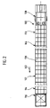
- FIG. 1 and 2 includes the tunnel 104 the following, along the direction of passage 102 successive components: an airlock 108, a pretreatment area 110, a diving area 112 and an aftertreatment area 114.
- Areas of the cabin 100 include the same as a whole with 118 designated conveyor, which is a linear, includes endlessly closed conveyor 120, the course in Fig. 1 schematically in dash-dotted lines is.
- the funding 120 is in the embodiment described here the cabin 100 is double-stranded, each Strand of the conveyor 120 through a conveyor chain 122 is formed.
- the conveyor device 118 of the embodiment described here the cabin 100 is designed as a shuttle conveyor, such as can be seen from Figures 3 to 5.
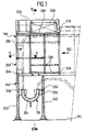
- FIG 3 shows a cross section through the tunnel 104 in the pre-treatment area 110, which is currently a vehicle body 124 is located in the area of the cutting plane.
- the tunnel 104 includes vertical support beams 126 (see FIG. 1 and 2), between which there are flat, vertical side walls 128 extend (see Fig. 3).
- the interior 130 of the tunnel 104 facing inner sides of the side walls 128 are by bevelled sheet metal panels with a material thickness of, for example, 3 mm.
- the outside of the side walls 128 are formed, for example, by trapezoidal sheets 134.
- the space between the sheet metal panels 132 and Trapezoidal sheets 134 are filled with thermal insulation 136, which can include rock wool mats, for example.
- the floor of the tunnel 104 is formed by a floor plate 138, which has a slope to drain wet medium to enable, which in the pretreatment area 110 for cleaning the vehicle bodies 124 before the surface treatment of the bodies in the diving area 112 of the cabin 100 is used.
- the roof 139 of the tunnel 104 comprises two parallel to the Passing direction 102 flat roof areas 140a, 140b and one arranged between the flat roof areas Pitched roof area 142.
- the roof is horizontal aligned.
- the roof 139 has an inclination of 30 ° to the horizontal.
- the pointed roof area 142 has two partial areas 144a, 144b on, which with respect to the longitudinal median plane 146 of the tunnel 104 are symmetrical to each other and aligned.
- Both partial areas 144a, 144b of the pointed roof area 142 rise at an angle of 30 ° to the longitudinal median plane 146 and abut a central one in the longitudinal median plane 146 First 148 together.
- Each of the partial areas 144a, 144b in turn comprises one outer portion 150, which extends from the ridge 148 down extends to the point where the respectively assigned Flat roof area 140a or 140b to the respective partial area 144a or 144b abuts.
- This outer section 150 of each Subarea 144a, 144b forms part of the outer contour of the roof 139.
- each of the partial areas 144a, 144b of the pointed roof area comprises 142 an inner portion 152 which is from the point at which the respectively assigned flat roof area 140a or 140b to the respective partial area 144a, 144b of the pointed roof area 142 abuts down to a lower edge 154 of the respective partial area 144a or 144b extends.
- This inner section 152 of each Subarea 144a, 144b protrudes into the interior 130 of the tunnel 104 and does not form part of the outer contour of the roof 139.
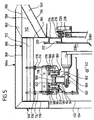
- the tunnel 104 As with the side walls 128 of the tunnel 104, it is also in the different areas of the roof 139 Inside by a sheet metal panel 156 and the respective Outside formed by a trapezoidal sheet 158 (see Fig. 5).
- the space between the sheet metal panels and the trapezoidal sheets 158 is by thermal insulation 160, for example can consist of rock wool mats, filled.
- each U-support profile 166 is an underside of the respective flat roof area 140a or 140b, while a vertical outer leg adjoining the web 168 170 of the U-support profile 166 an upper edge of the inside of the respective side wall 128.
- a lower edge of the outer leg 170 is horizontal Folded towards the outside and lies on an in correspondingly folded upper edge of the sheet metal panel 132 of the side wall 128.
- each U-support profile 166 angled reinforcing elements 171 held which is in the space between the U-support profile 166 and the trapezoidal sheet 158 extend transversely to the direction of passage 102 and spaced apart from one another along the direction of passage 102 are.
- each of the U-support profiles 166 each extend one A plurality of suspension trusses 172 which are perpendicular to the Pass direction 102 aligned and along the pass direction 102 are spaced from each other (see Fig. 5).
- each of the suspension trusses 172 are each by means of two U-shaped bends, the respective suspension crossbar 172 encompassing threaded rods 174, arranged on the same Nuts 176 and clamping devices arranged on the same 177 two guide rails extending in the direction of passage 102 180 set, the two guide rails 180 essentially U-shaped cross sections have the open sides facing each other are.
- the two guide rails 180 are by means of yokes 178, which is essentially the shape of a downward open U, connected to each other, with each of the mutually facing inner sides of the vertical legs each Yokes 178 each one of the guide rails 180, preferably by welding.
- substantially horizontal guide legs 182 of the guide rails 180 each roll a guide roller 184, both of which are opposite to each other Ends of a link 186 rotatably supported are.
- Each of the links 186 is rigid with a conveyor chain 122 connected which extends along the conveyor chain 122 successive alternating internal and external Link plates 188 composed.
- the link plates 188 are each in pairs transverse to the direction of passage 102 spaced apart. Along the direction of passage 102 successive link plates are in a vertical Level pivotally connected to each other so that the Conveyor chain describe 122 arches in this vertical plane can.
- the longitudinal center plane 146 of the tunnel 104 is symmetrical to one another arranged bearing sleeves 192 the two ends of a substantially U-shaped pendulum 194 pivoted.
- Each of the pendulums 194 carries in the area of its horizontal Web fixing devices 196, through which a (not shown) Skid frame with a vehicle body arranged on it 124 fixed to the respective pendulum 194 can be.
- Two U-shaped pendulums 194 each carry together a skid frame with a vehicle body arranged thereon 124.
- the pointed roof area covers 142 of the roof 139 of the tunnel 104 the track of the vehicle bodies 124 through the tunnel 104 in its entire width.
- the through the two mutually assigned guide rails 180 chain guideways 206 formed are in front that generated by means of the spray devices 198, 200 and 202 Spray mist protected by cover plates 208a, 208b, which, in the direction 102 in succession, alternately on an upper holding bar 210 or on a lower one Retaining strip 212 are suspended, along the direction of passage 102 successive cover plates 208 each other partially overlap so that a complete shielding of the Chain guideways 206 guaranteed before the spray is.
- Each carrier 224 each hold a basket 226 of the inspection cart 222, in which an operator by the Interior 130 of tunnel 104 can be pulled out for maintenance or carry out cleaning work.
- tunnel 104 is both in the pre-treatment area 110 as well as in the diving area 112 and formed in the aftertreatment area 114.
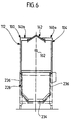
- the tunnel 104 becomes as shown in FIGS 1 and 6 can be seen, not down through a floor pan limited; rather is in this area below of the tunnel 104, a plunge pool 228 is arranged, which according to at the front or to the rear through an inlet slope 230 or a discharge slope 232, down through a horizontal Bottom wall 234, which preferably has a slope, and is laterally delimited by side walls 236.
- the plunge pool 228 is depending on the type of to be carried out Surface treatment with a pre-treatment liquid or with dip coating for cathodic electro-dip coating filled.
- For immersion in the respective treatment liquid are the chain guideways 206 in the diving area 112 lowered, as can be seen from Fig. 1.
- the tunnel 104 described above points because of its Roof construction, in which a pointed roof area 142 between two flat roof areas 140a, 140b is integrated, see that not the entire pointed roof area 142, but only outer portions 150 of partial areas 144a, 144b of the pointed roof area 142 upwards over the flat roof areas 140a, 140b, one with the same amount of funding Vehicle bodies 124 typically 20% less overall height than conventional tunnels, the roof of which covers the entire Tunnel width is designed as a pointed roof.
- tunnel 104 from the bottom of the floor pan 138 to ridge 148 is therefore typically only approximate 4.0 m. Due to this low height, it is possible completely prefabricated tunnel sections (so-called shots) on suitable transport vehicles, especially flatbed trucks, through hall gates of the usual height in the automotive industry to be transported as a whole to the workshop in which the Cabin 100 for surface treatment of vehicle bodies to be installed.
- tunnel sections have a length of, for example 10.4 m and can be completely pre-assembled, with integrated floor pan 138, built-in parts, such as for example spray devices, and already pre-assembled Thermal insulation 136, 160 are delivered to the installation site.
- built-in parts such as for example spray devices
- Thermal insulation 136, 160 are delivered to the installation site.
- the conveying means 120 of the conveying device 118 of the cabin 100 is purely schematic by means of one in FIGS. 7, 8 and 10 shown drive unit 238, which to the drive tower 116 is arranged, driven to rotate.
- the drive tower comprises 116 a support structure 240, which in turn comprises several, for example four, vertical support pillars 242, which are supported on a base 244 of the cabin 100 and a horizontal base frame at its upper ends 246 bear, which two are parallel to the direction of flow 102 extending and perpendicular to the direction of passage 102 from each other spaced longitudinal beams 248 and one transverse to Direction of passage 102 towards one longitudinal beam 248 the other longitudinal member 248 extending cross member 250.
- a support structure 240 which in turn comprises several, for example four, vertical support pillars 242, which are supported on a base 244 of the cabin 100 and a horizontal base frame at its upper ends 246 bear, which two are parallel to the direction of flow 102 extending and perpendicular to the direction of passage 102 from each other spaced longitudinal beams 248 and one transverse to Direction of passage 102 towards one longitudinal beam 248 the other longitudinal member 248 extending cross member 250.
- the pillars 242, the side members 248 and the cross member 250 are made by profile steel elements, in particular by double-T steel beams, educated.
- tensioning device 252 held which one for each strand of the conveyor 120 substantially U-shaped chain guide track section 254 comprises, under the action of a (not shown)
- the clamping weight can be moved in the vertical direction on stationary Areas 256 of the tensioning device 252 is guided to the conveyor chains 122 of the conveyor 118 under tension to keep.
- the stationary areas 256 of the jig 252 are by means of a (not shown) clamping device on the Support pillars 242 of the support structure 240 held.
- the base frame 246 of the drive tower 116 is supported self-supporting housing 258, which is parallel to the direction of flow 102 aligned sidewalls 260 and one across the side walls 260 aligned with the direction of passage 102 interconnecting and an (not shown) outlet for the vehicle bodies 124 Rear wall 262 includes.
- the rear wall 262 is made of C-shaped sheet metal panels 264 formed, which is flat at bent areas 266 abut each other and on these areas, for example connected by screwing or welding are. These metal panels 264 form the inside of the rear wall 262.
- the outside of the back wall 262 is through trapezoidal sheets 268 formed, which at second folded regions 270 of the Sheet metal panels 264, for example by screwing or welding, are set.
- the space between the sheet panels 264 and the trapezoidal sheets 268 can be made of rock wool mats, for example existing heat insulation 272 must be filled.
- the side walls 260 of the housing 258 are similar like the rear wall 262 made of C-shaped sheet metal panels 264, trapezoidal sheets 268 and thermal insulation arranged in between 272 trained; to increase the load capacity however, side walls 260 additionally include the same between two successive metal panels 264 arranged Carrying profiles 274, which also essentially one C-shaped cross-section and by folding are formed from a metal sheet, which has a greater material thickness than the sheet of sheet metal panels 264.
- three mm can be used to manufacture the sheet metal panels strong steel sheet and for the production of the support profiles 274 a 5 mm thick steel sheet can be used.
- the support profiles 274 lie with first folded areas 276 on the first folded Areas 266 of the respective adjacent sheet metal panels 264 flat and are with the same by screwing or Welding connected.
- the side walls 260 of the housing 258 essentially carry one rectangular, horizontal holding frame 278 (see Fig. 7 and 10) which, like the base frame 246, is parallel longitudinal beams 280 and running transversely to the direction of passage 102, the two longitudinal beams Includes 280 interconnecting cross beams 282.
- the sheet metal panels 264 of the side walls 260 folded at its upper edges in a horizontal direction, to form support surfaces 284 for the holding frame 278.
- these contact surfaces are 284 provided with elongated holes 286 to accommodate fasteners, especially screws, through which the holding frame 278 can be connected to the housing 258.
- fasteners longitudinally within the elongated holes 286 in the direction 102, it is possible to when flanging the holding frame 278 to the housing 258 Holding frame 278 to be precisely adjusted along the direction of passage 102 and thus to compensate for manufacturing tolerances.
- the modular design Drive unit 238 of the conveyor 118 set On the holding frame 278 is the modular design Drive unit 238 of the conveyor 118 set.
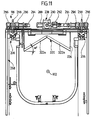
- the drive unit 238 shown in FIG. 11 includes one Gear motor 288, an intermediate gear 290 with two output shafts 292, which via intermediate cardan shafts 294 each rotatably mounted in pillow block bearings 296 Drive the Caterpillar drive sprocket 298.
- Caterpillar tension sprocket is a Caterpillar chain (not shown) tensioned, which each with one of the conveyor chains 122nd the conveyor 118 is engaged, which in below the Caterpillar drive sprockets 298 parallel to the direction of travel 102 extending chain guide tracks 206 are.
- All components of the drive unit 238 are direct or indirectly fixed to the holding frame 278 so that the Holding frame 278 and the drive unit 238 together a done Form pre-assembled module, which is completely assembled delivered to the installation site of the cabin 100 and as a whole by means of suitable fastening means, in particular screws, to the self-supporting housing 258 of the drive tower 116 is flanged.
- the self-supporting housing 258 can also be used with all internals completely pre-assembled and as a pre-assembled unit the installation location of the cabin 100 are delivered.
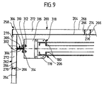
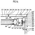
- housing 258 include two on the inside the rear wall 262 fixed in the vertical direction extending clamping rails 300, which consist of two L-profiles 302 are assembled, the long legs 304 together apply (see Fig. 9).
- clamping plates 310 and lock nuts 312 die vertically aligned clamping edges 314 several in vertical Direction of horizontal holding plates arranged one below the other 316 clamped.
- Each of the holding plates 316 holds a suspension bracket 178, on which the two together form a chain guideway 206 forming guide rails 180 are held.
- the clamping rails 300 are thus used to hang through the rear of the housing 258 vertical Chain guide track sections 318.
- FIGS. 7 and 10 are on the inside of the side walls 260 of the housing 258 also horizontal Clamping rails 320 set which of the attachment further device installations, for example sensors and in the same way as the vertical clamping rails 300 are composed of two L-profiles.
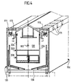
- housing 258 In its area lying at the front in the direction of passage 102 housing 258 further includes an inclined floor pan 320 provided, the slope against the direction 102 is directed to those conveyed through the housing 258 Vehicle bodies 124 dripping wet medium into the tunnel 104 to be returned.
- the vehicle bodies 124 have a pointed roof 320, which formed two symmetrically to the longitudinal center plane 146 and arranged partial areas 322a, 322b, which each at an angle of 30 ° to the horizontal are inclined.
- Wet medium condenses on the pointed roof 320 Vehicle bodies 124 in vapor form from the tunnel 104 in the housing 258 of the drive tower 116 is entered. Because of The condensed roof drips on the slope of the pointed roof 320 Wet medium not from above on through the housing 258 funded vehicle bodies 124, but runs down its underside up to the lower edges 324 of the partial areas 322a, 322b, from where the condensate to the side of the Vehicle bodies 124 drip down so that no condensate gets to the vehicle bodies where there is paint damage could lead.
- the housing 258 is also in shape with a top wall 327 a horizontal ceiling plate, which is from the Sidewalls 260 and rear wall 262 is carried and through an operator is accessible to the drive unit 238 to check and maintain.
- a die Ceiling wall 327 serving operator serve railings 329, which is arranged along the edges of the ceiling wall 327 are.
- both correspond the overall width of the self-supporting housing 258 as well its clear width (i.e. the distance between the side walls 260) exactly the total width or the clear width of the arranged in the pass direction 102 in front of the drive tower 116 Section of tunnel 104.
- tunnel 104 and housing 258 in simply by a screw or welded connection be connected to each other.
- the side walls of tunnel 104 and the housing are aligned 258 with each other, so that a continuous smooth outer surface arises, which is easy to clean.
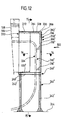
- the also includes input-side deflection tower 106 of the cabin 100 a support structure 240 ', which in turn several, for example includes four vertical pillars 242 ', which are located on the ground Support 244 of the cabin 100 and at their upper ends carry a horizontal base frame 246 ', which two extending parallel to the direction 102 and spaced apart perpendicular to the direction of passage 102 Side members 248 'and one transverse to the direction 102 from one side member 248 'to the other side member 248 'extending cross member 250'.
- a support structure 240 ' which in turn several, for example includes four vertical pillars 242 ', which are located on the ground Support 244 of the cabin 100 and at their upper ends carry a horizontal base frame 246 ', which two extending parallel to the direction 102 and spaced apart perpendicular to the direction of passage 102 Side members 248 'and one transverse to the direction 102 from one side member 248 'to the other side member 248 'extending cross member 250'
- the pillars 242 ', the side members 248' and the cross member 250 ' are made by profile steel elements, in particular by Double-T steel beam, formed.
- the base frame 246 'of the deflection tower 106 is supported self-supporting housing 258 ', which is parallel to the direction of flow 102 aligned sidewalls 260 'and one across the side walls 260 ′ aligned with the direction of passage 102 interconnecting and an (not shown) entry opening for the vehicle bodies 124 Front wall 262 'includes.
- the front wall 262 'and the side walls 260' formed from C-shaped sheet metal panels 264, which on the first folded areas 266 lie flat against one another and on these areas, for example by screwing or Welding, are interconnected. These metal panels 264 form the inner sides of the front wall 262 'and the side walls 260 '.
- the outer sides of the front wall 262 'and the side walls 260' are formed by trapezoidal sheets 268, which are folded on second Areas 270 of the sheet metal panels 264, for example by screwing or welding.
- the gaps between the sheet panels 264 and the trapezoidal sheets 268 are made of rock wool mats, for example existing thermal insulation 272 filled.
- 3 mm can be used to produce the sheet metal panels 264 strong steel sheet can be used.
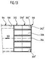
- top wall 328 To increase the rigidity of the top wall 328 are on the The underside thereof is parallel to the direction 102 extending reinforcement profiles 330 (see Fig. 12) with a T-shaped Cross section set.
- the internals of the self-supporting housing 258 ' comprise two fixed to the inside of the front wall 262 ', in vertically extending clamping rails 300 'that two L-profiles 302 'are assembled, their long legs 304 'abut each other.
- the clamping rails 300 'thus serve to suspend through the vertical portion of the front of housing 258 ' Chain guide track sections 318 '.
- the housing 258 ' In its area lying at the rear in the direction of passage 102
- the housing 258 ' is also with an inclined bottom pan 320 'provided, their slope parallel to the direction of flow 102 is directed to those conveyed through the housing 258 ' Vehicle bodies 124 dripping wet medium in the To derive tunnel 104.
- both correspond the overall width of the self-supporting housing 258 'as well its clear width (i.e. the distance between the side walls 260 ') exactly the total width or the clear width of the arranged in the direction of passage 102 after the deflection tower 106 Section of tunnel 104, namely the airlock 108.
- tunnel 104 and housing 258 'in simply by a screw or welded connection be connected to each other.
- the side walls of tunnel 104 and the housing are aligned 258 'with each other, so that a continuous smooth outer surface arises, which is easy to clean.
- a suction hood 332 for the immediately following the self-supporting housing 258 'arranged airlock 108.
- the vertical chain guide track sections 318 ' form together with upstream and downstream curved chain guide sections a deflection unit 334 of the conveyor device 118, which on the self-supporting housing 258 'of the deflection tower 106 is held.
Landscapes
- Engineering & Computer Science (AREA)
- Manufacturing & Machinery (AREA)
- Chemical & Material Sciences (AREA)
- Combustion & Propulsion (AREA)
- Transportation (AREA)
- Mechanical Engineering (AREA)
- Body Structure For Vehicles (AREA)
- Automobile Manufacture Line, Endless Track Vehicle, Trailer (AREA)
- Spray Control Apparatus (AREA)
Applications Claiming Priority (2)
| Application Number | Priority Date | Filing Date | Title |
|---|---|---|---|
| DE1999157606 DE19957606A1 (de) | 1999-11-30 | 1999-11-30 | Kabine zur Oberflächenbehandlung von Fahrzeugkarosserien |
| DE19957606 | 1999-11-30 |
Publications (2)
| Publication Number | Publication Date |
|---|---|
| EP1106490A2 true EP1106490A2 (fr) | 2001-06-13 |
| EP1106490A3 EP1106490A3 (fr) | 2002-11-27 |
Family
ID=7930863
Family Applications (1)
| Application Number | Title | Priority Date | Filing Date |
|---|---|---|---|
| EP00125461A Withdrawn EP1106490A3 (fr) | 1999-11-30 | 2000-11-21 | Cabine pour le traitement de carrosseries de vehicules |
Country Status (2)
| Country | Link |
|---|---|
| EP (1) | EP1106490A3 (fr) |
| DE (1) | DE19957606A1 (fr) |
Families Citing this family (1)
| Publication number | Priority date | Publication date | Assignee | Title |
|---|---|---|---|---|
| DE102007031822A1 (de) * | 2007-07-07 | 2009-01-08 | Dürr Systems GmbH | Abdichtvorrichtung |
Family Cites Families (7)
| Publication number | Priority date | Publication date | Assignee | Title |
|---|---|---|---|---|
| US4904365A (en) * | 1988-02-29 | 1990-02-27 | Trinity Industrial Corporation | Electrodeposition coating facility |
| JPH0813639B2 (ja) * | 1988-07-26 | 1996-02-14 | 本田技研工業株式会社 | 吊下げ搬送装置 |
| JPH0772012B2 (ja) * | 1988-10-28 | 1995-08-02 | 株式会社椿本チエイン | 物品の離隔搬送装置 |
| DE3940231A1 (de) * | 1989-12-05 | 1991-06-06 | Duerr Gmbh & Co | Foerdereinrichtung |
| US5947266A (en) * | 1992-11-06 | 1999-09-07 | Rionde Sa | Protective and insulating enclosure with removable panels for a transfer unit |
| DE19848946C2 (de) * | 1998-10-23 | 2000-08-10 | Eisenmann Kg Maschbau | Pendelförderer |
| DE20004097U1 (de) * | 2000-03-04 | 2000-08-03 | Dürr Systems GmbH, 70435 Stuttgart | Antriebseinheit für eine Fördervorrichtung |
-
1999
- 1999-11-30 DE DE1999157606 patent/DE19957606A1/de not_active Withdrawn
-
2000
- 2000-11-21 EP EP00125461A patent/EP1106490A3/fr not_active Withdrawn
Non-Patent Citations (1)
| Title |
|---|
| None |
Also Published As
| Publication number | Publication date |
|---|---|
| DE19957606A1 (de) | 2001-05-31 |
| EP1106490A3 (fr) | 2002-11-27 |
Similar Documents
| Publication | Publication Date | Title |
|---|---|---|
| EP1111160B1 (fr) | Parc de stationnement démontable | |
| EP3024771B1 (fr) | Palette de trottoir roulant | |
| EP2265521B1 (fr) | Bande transporteuse pour une installation de transport en longueur comportant des parois latérales s'étendant en longueur | |
| DE102007020589B4 (de) | Nutzfahrzeug, Boden für ein Nutzfahrzeug, Verfahren zur Herstellung eines Nutzfahrzeugs | |
| EP2882634A1 (fr) | Dispositif de transport surélevé doté de portiques à colonnes | |
| EP0999154A1 (fr) | Transporteur à navettes | |
| DE2136197B2 (de) | Vorrichtung für die Abluftreinigung einer Fabrikhalle | |
| EP1106491A2 (fr) | Cabine pour le traitement de surface de carrosseries automobiles | |
| EP3049316B1 (fr) | Système de convoyeur aérien à monter au plafond d'une ligne de montage | |
| EP1106490A2 (fr) | Cabine pour le traitement de carrosseries de vehicules | |
| DE10200982A1 (de) | Transporteinrichtung | |
| EP1059223A1 (fr) | Berceaux pour le transport de pièces à travailler, en particulier de carosseries de véhicules, et dispositif de rotation pour retourner ces berceaux | |
| DE69400434T2 (de) | Kratzer, kratzerrahmen ausgestattet mit kratzer, materialfördervorrichtung und verstellbare zellulare kabine | |
| AT407870B (de) | Doppelgurtförderanlage | |
| DE69004235T2 (de) | Viadukt für Eisenbahngleise. | |
| DE3348204C2 (en) | Frame for belt conveyor apparatuses | |
| DE2945665A1 (de) | Foerderer, insbesondere scharnierbandfoerderer | |
| DE3318174A1 (de) | Rahmen fuer bandfoerdervorrichtungen | |
| DE10027758A1 (de) | Mobile Kabine | |
| DE9320706U1 (de) | Wandkonstruktion für eine Kabine einer Lackieranlage | |
| CH290983A (de) | Rolltreppe für Personen und Lasten. | |
| DE2010662A1 (de) | Konstruktion für Fordermittel wie Fahrsteigen, Fahrtreppen oder dergleichen | |
| EP3577050B1 (fr) | Élément de sous-plancher pour une courroie de transporteur de passager | |
| EP3049315A1 (fr) | Système de convoyeur aérien à monter au plafond d'une ligne de montage | |
| DE102022118001A1 (de) | Tragkonstruktion für eine Fahrtreppe oder einen Fahrsteig |
Legal Events
| Date | Code | Title | Description |
|---|---|---|---|
| PUAI | Public reference made under article 153(3) epc to a published international application that has entered the european phase |
Free format text: ORIGINAL CODE: 0009012 |
|
| AK | Designated contracting states |
Kind code of ref document: A2 Designated state(s): AT BE CH CY DE DK ES FI FR GB GR IE IT LI LU MC NL PT SE TR |
|
| AX | Request for extension of the european patent |
Free format text: AL;LT;LV;MK;RO;SI |
|
| PUAL | Search report despatched |
Free format text: ORIGINAL CODE: 0009013 |
|
| AK | Designated contracting states |
Kind code of ref document: A3 Designated state(s): AT BE CH CY DE DK ES FI FR GB GR IE IT LI LU MC NL PT SE TR |
|
| AX | Request for extension of the european patent |
Free format text: AL;LT;LV;MK;RO;SI |
|
| RIC1 | Information provided on ipc code assigned before grant |
Free format text: 7B 62D 65/00 A, 7B 65G 21/08 B, 7B 65G 49/02 B |
|
| AKX | Designation fees paid | ||
| REG | Reference to a national code |
Ref country code: DE Ref legal event code: 8566 |
|
| STAA | Information on the status of an ep patent application or granted ep patent |
Free format text: STATUS: THE APPLICATION IS DEEMED TO BE WITHDRAWN |
|
| 18D | Application deemed to be withdrawn |
Effective date: 20030603 |