EP1106771A2 - Bauelement mit einer Kabeldurchführung sowie Herstellungsverfahren für dasselbe - Google Patents
Bauelement mit einer Kabeldurchführung sowie Herstellungsverfahren für dasselbe Download PDFInfo
- Publication number
- EP1106771A2 EP1106771A2 EP00403405A EP00403405A EP1106771A2 EP 1106771 A2 EP1106771 A2 EP 1106771A2 EP 00403405 A EP00403405 A EP 00403405A EP 00403405 A EP00403405 A EP 00403405A EP 1106771 A2 EP1106771 A2 EP 1106771A2
- Authority
- EP
- European Patent Office
- Prior art keywords
- plates
- space
- wires
- drilled hole
- surrounded
- Prior art date
- Legal status (The legal status is an assumption and is not a legal conclusion. Google has not performed a legal analysis and makes no representation as to the accuracy of the status listed.)
- Granted
Links
- 238000010276 construction Methods 0.000 title claims description 25
- 238000004519 manufacturing process Methods 0.000 title claims description 5
- 238000000034 method Methods 0.000 title claims description 4
- 239000011229 interlayer Substances 0.000 claims abstract description 26
- 125000006850 spacer group Chemical group 0.000 claims abstract description 25
- 238000009432 framing Methods 0.000 claims abstract 2
- 239000002131 composite material Substances 0.000 claims description 14
- 238000007789 sealing Methods 0.000 claims description 7
- 238000009795 derivation Methods 0.000 claims description 3
- 238000005304 joining Methods 0.000 claims description 2
- 239000011521 glass Substances 0.000 description 17
- 210000004027 cell Anatomy 0.000 description 13
- 238000000465 moulding Methods 0.000 description 6
- 239000010410 layer Substances 0.000 description 4
- 230000000694 effects Effects 0.000 description 3
- 239000000853 adhesive Substances 0.000 description 2
- 230000001070 adhesive effect Effects 0.000 description 2
- 230000007797 corrosion Effects 0.000 description 2
- 238000005260 corrosion Methods 0.000 description 2
- 230000002093 peripheral effect Effects 0.000 description 2
- 239000011347 resin Substances 0.000 description 2
- 229920005989 resin Polymers 0.000 description 2
- 230000000007 visual effect Effects 0.000 description 2
- 239000011324 bead Substances 0.000 description 1
- 230000005540 biological transmission Effects 0.000 description 1
- 125000000484 butyl group Chemical group [H]C([*])([H])C([H])([H])C([H])([H])C([H])([H])[H] 0.000 description 1
- 239000011248 coating agent Substances 0.000 description 1
- 238000000576 coating method Methods 0.000 description 1
- 239000013078 crystal Substances 0.000 description 1
- 210000002858 crystal cell Anatomy 0.000 description 1
- 238000009826 distribution Methods 0.000 description 1
- 238000005553 drilling Methods 0.000 description 1
- 239000003292 glue Substances 0.000 description 1
- 239000011147 inorganic material Substances 0.000 description 1
- 239000005340 laminated glass Substances 0.000 description 1
- 239000004973 liquid crystal related substance Substances 0.000 description 1
- 239000000463 material Substances 0.000 description 1
- 238000005259 measurement Methods 0.000 description 1
- 239000002184 metal Substances 0.000 description 1
- 239000000203 mixture Substances 0.000 description 1
- 239000011368 organic material Substances 0.000 description 1
- 230000002085 persistent effect Effects 0.000 description 1
- 229920001021 polysulfide Polymers 0.000 description 1
- 239000000565 sealant Substances 0.000 description 1
- 229920002994 synthetic fiber Polymers 0.000 description 1
- 239000010409 thin film Substances 0.000 description 1
- 230000007704 transition Effects 0.000 description 1
- 239000012780 transparent material Substances 0.000 description 1
Images
Classifications
-
- B—PERFORMING OPERATIONS; TRANSPORTING
- B32—LAYERED PRODUCTS
- B32B—LAYERED PRODUCTS, i.e. PRODUCTS BUILT-UP OF STRATA OF FLAT OR NON-FLAT, e.g. CELLULAR OR HONEYCOMB, FORM
- B32B17/00—Layered products essentially comprising sheet glass, or glass, slag, or like fibres
- B32B17/06—Layered products essentially comprising sheet glass, or glass, slag, or like fibres comprising glass as the main or only constituent of a layer, next to another layer of a specific material
- B32B17/10—Layered products essentially comprising sheet glass, or glass, slag, or like fibres comprising glass as the main or only constituent of a layer, next to another layer of a specific material of synthetic resin
- B32B17/10005—Layered products essentially comprising sheet glass, or glass, slag, or like fibres comprising glass as the main or only constituent of a layer, next to another layer of a specific material of synthetic resin laminated safety glass or glazing
- B32B17/10009—Layered products essentially comprising sheet glass, or glass, slag, or like fibres comprising glass as the main or only constituent of a layer, next to another layer of a specific material of synthetic resin laminated safety glass or glazing characterized by the number, the constitution or treatment of glass sheets
- B32B17/10036—Layered products essentially comprising sheet glass, or glass, slag, or like fibres comprising glass as the main or only constituent of a layer, next to another layer of a specific material of synthetic resin laminated safety glass or glazing characterized by the number, the constitution or treatment of glass sheets comprising two outer glass sheets
- B32B17/10045—Layered products essentially comprising sheet glass, or glass, slag, or like fibres comprising glass as the main or only constituent of a layer, next to another layer of a specific material of synthetic resin laminated safety glass or glazing characterized by the number, the constitution or treatment of glass sheets comprising two outer glass sheets with at least one intermediate layer consisting of a glass sheet
- B32B17/10055—Layered products essentially comprising sheet glass, or glass, slag, or like fibres comprising glass as the main or only constituent of a layer, next to another layer of a specific material of synthetic resin laminated safety glass or glazing characterized by the number, the constitution or treatment of glass sheets comprising two outer glass sheets with at least one intermediate layer consisting of a glass sheet with at least one intermediate air space
-
- E—FIXED CONSTRUCTIONS
- E06—DOORS, WINDOWS, SHUTTERS, OR ROLLER BLINDS IN GENERAL; LADDERS
- E06B—FIXED OR MOVABLE CLOSURES FOR OPENINGS IN BUILDINGS, VEHICLES, FENCES OR LIKE ENCLOSURES IN GENERAL, e.g. DOORS, WINDOWS, BLINDS, GATES
- E06B3/00—Window sashes, door leaves, or like elements for closing wall or like openings; Layout of fixed or moving closures, e.g. windows in wall or like openings; Features of rigidly-mounted outer frames relating to the mounting of wing frames
- E06B3/54—Fixing of glass panes or like plates
- E06B3/5436—Fixing of glass panes or like plates involving holes or indentations in the pane
-
- E—FIXED CONSTRUCTIONS
- E06—DOORS, WINDOWS, SHUTTERS, OR ROLLER BLINDS IN GENERAL; LADDERS
- E06B—FIXED OR MOVABLE CLOSURES FOR OPENINGS IN BUILDINGS, VEHICLES, FENCES OR LIKE ENCLOSURES IN GENERAL, e.g. DOORS, WINDOWS, BLINDS, GATES
- E06B3/00—Window sashes, door leaves, or like elements for closing wall or like openings; Layout of fixed or moving closures, e.g. windows in wall or like openings; Features of rigidly-mounted outer frames relating to the mounting of wing frames
- E06B3/66—Units comprising two or more parallel glass or like panes permanently secured together
- E06B3/6621—Units comprising two or more parallel glass or like panes permanently secured together with special provisions for fitting in window frames or to adjacent units; Separate edge protecting strips
-
- H—ELECTRICITY
- H02—GENERATION; CONVERSION OR DISTRIBUTION OF ELECTRIC POWER
- H02G—INSTALLATION OF ELECTRIC CABLES OR LINES, OR OF COMBINED OPTICAL AND ELECTRIC CABLES OR LINES
- H02G3/00—Installations of electric cables or lines or protective tubing therefor in or on buildings, equivalent structures or vehicles
- H02G3/02—Details
- H02G3/08—Distribution boxes; Connection or junction boxes
- H02G3/081—Bases, casings or covers
- H02G3/083—Inlets
-
- H—ELECTRICITY
- H10—SEMICONDUCTOR DEVICES; ELECTRIC SOLID-STATE DEVICES NOT OTHERWISE PROVIDED FOR
- H10F—INORGANIC SEMICONDUCTOR DEVICES SENSITIVE TO INFRARED RADIATION, LIGHT, ELECTROMAGNETIC RADIATION OF SHORTER WAVELENGTH OR CORPUSCULAR RADIATION
- H10F19/00—Integrated devices, or assemblies of multiple devices, comprising at least one photovoltaic cell covered by group H10F10/00, e.g. photovoltaic modules
- H10F19/80—Encapsulations or containers for integrated devices, or assemblies of multiple devices, having photovoltaic cells
- H10F19/807—Double-glass encapsulation, e.g. photovoltaic cells arranged between front and rear glass sheets
-
- H—ELECTRICITY
- H10—SEMICONDUCTOR DEVICES; ELECTRIC SOLID-STATE DEVICES NOT OTHERWISE PROVIDED FOR
- H10F—INORGANIC SEMICONDUCTOR DEVICES SENSITIVE TO INFRARED RADIATION, LIGHT, ELECTROMAGNETIC RADIATION OF SHORTER WAVELENGTH OR CORPUSCULAR RADIATION
- H10F77/00—Constructional details of devices covered by this subclass
- H10F77/93—Interconnections
- H10F77/933—Interconnections for devices having potential barriers
- H10F77/935—Interconnections for devices having potential barriers for photovoltaic devices or modules
-
- H—ELECTRICITY
- H02—GENERATION; CONVERSION OR DISTRIBUTION OF ELECTRIC POWER
- H02G—INSTALLATION OF ELECTRIC CABLES OR LINES, OR OF COMBINED OPTICAL AND ELECTRIC CABLES OR LINES
- H02G3/00—Installations of electric cables or lines or protective tubing therefor in or on buildings, equivalent structures or vehicles
- H02G3/22—Installations of cables or lines through walls, floors or ceilings, e.g. into buildings
-
- Y—GENERAL TAGGING OF NEW TECHNOLOGICAL DEVELOPMENTS; GENERAL TAGGING OF CROSS-SECTIONAL TECHNOLOGIES SPANNING OVER SEVERAL SECTIONS OF THE IPC; TECHNICAL SUBJECTS COVERED BY FORMER USPC CROSS-REFERENCE ART COLLECTIONS [XRACs] AND DIGESTS
- Y02—TECHNOLOGIES OR APPLICATIONS FOR MITIGATION OR ADAPTATION AGAINST CLIMATE CHANGE
- Y02B—CLIMATE CHANGE MITIGATION TECHNOLOGIES RELATED TO BUILDINGS, e.g. HOUSING, HOUSE APPLIANCES OR RELATED END-USER APPLICATIONS
- Y02B10/00—Integration of renewable energy sources in buildings
- Y02B10/10—Photovoltaic [PV]
-
- Y—GENERAL TAGGING OF NEW TECHNOLOGICAL DEVELOPMENTS; GENERAL TAGGING OF CROSS-SECTIONAL TECHNOLOGIES SPANNING OVER SEVERAL SECTIONS OF THE IPC; TECHNICAL SUBJECTS COVERED BY FORMER USPC CROSS-REFERENCE ART COLLECTIONS [XRACs] AND DIGESTS
- Y02—TECHNOLOGIES OR APPLICATIONS FOR MITIGATION OR ADAPTATION AGAINST CLIMATE CHANGE
- Y02E—REDUCTION OF GREENHOUSE GAS [GHG] EMISSIONS, RELATED TO ENERGY GENERATION, TRANSMISSION OR DISTRIBUTION
- Y02E10/00—Energy generation through renewable energy sources
- Y02E10/50—Photovoltaic [PV] energy
Definitions
- the invention relates to a flat building element with a passage of wires having the characteristics of the preamble of the claim 1.
- Document DE 295 09 193 U1 we know a building element flat with electrical functional elements, especially cells solar, whose electrical connection wires are led to the outside out of the building element.
- the building element constitutes overall insulating glazing composed of two transparent panes assembled by means of a frame-shaped spacer.
- a first window of it is a composite glass with several sheets, inside which are arranged electrical functional elements.
- solar cells are embedded in a layer of molding resin, which fills the gap between two parallel windows.
- the aforementioned connecting wires are led out of the composite through a drilled or countersunk hole, which is provided in the exterior glass of the composite assembled with the spacer outside the space between the windows of the glazing circumscribed by the spacer, near the edge of the element construction.
- the connecting wires are then routed through a hole drilled from the second window of the insulating glass, which is also on the outside of the space between the panes of the glazing circumscribed by the spacer, at near the outer edge of the window.
- the space formed at the edge of the element of construction between the spacer and the faces of the panes facing one the other is completely filled with a sealing mass, which also coats the sons. In this way, the wires come out inside one of the main faces of the building element.
- This arrangement has the advantage that the space between the insulating glass panes are only surrounded by closed (glass) faces and by the spacer, so that no additional sealing measures are necessary.
- a certain disadvantage of this configuration is the distance relatively large from the spacer to the edge of the glass through which the wires are led outside.
- the section of the connection wires, which is led to the edge of the element can in some cases negatively influence the aesthetic visual effect of the building element, if it cannot be covered.
- the object of the invention is to propose a construction element of the type mentioned in the introduction, in which the location of the passage of the wires to through one of the main faces can be chosen very freely.
- the plates are advantageously panes in one opaque, translucent or transparent, inorganic or organic material, in particular in glass, and can be monolithic or laminated, in glazing single or multiple.
- the connecting wires through the space included between the plates surrounded by the frame-shaped spacer, we admit except that this space must include an opening for the exit of the wires.
- the annular interlayer known per se, a proven accessory which ensures, at a relatively low cost, good sealing of the space between the plates with respect to the drilled hole, by which the connecting wires exit from the building element.
- the drilled hole also opens into the circumscribed interior space by the annular interlayer. However, it does not have to be positioned in the center of this space.
- the free interior dimension of the interior space can also be larger than the diameter of the drilled hole, so that the edge thereof forms an undercut usable for fixing the element of construction.
- connection wires can be run invisibly on the rear side of the elements electrically functional outside the building element and must not first be led to the edge of it, where it is not in good standing general more functional elements.
- the carrier plate is a composite with several leaves, in which the functional elements are embedded.
- a hole in the composite plate facing the space between the plates must be arranged in such a way that the connecting wires penetrate therethrough in the space surrounded by the annular interlayer. This hole should not necessarily be in alignment with the hole drilled in the other plate. The manufacturing tolerances can be largely dimensioned in this respect.
- the hole is preferably filled with the same molding mass, which also coats the functional elements electrical in the intermediate space of the laminated plate.
- the function performed by the elements only plays a secondary role in the context of this invention. They can for example be photovoltaic solar cells and / or liquid crystal cells performing display or shading functions. In principle, we can also take into account elements antenna or heater, which must also be brought into contact electric to the outside by means of connection wires.
- a solar module which can be represented as an application preferred by a building element according to the invention
- several thin film or crystal photovoltaic solar cells are connected in series with each other.
- Each of them has a bypass diode directly connecting its two poles.
- this can acquire a high ohmic resistance and thus block the current flow of the whole series connection. If we authorized a current flow from other cells to this shaded cell, this one could heat up considerably beyond its normal temperature under the effect of the power supplied.
- the bypass diode allows short-circuit current flow when the internal resistance of the solar cell exceeds the voltage drop at the diode. Persistent damage from individual cells is thereby safely prevented.
- a hooking element point is fixed in a manner known per se, in the region of the interlayer annular, to one or both plates of the building element.
- the point attachment element is, for another function, provided with a passage for connection wires. This can be achieved by example by drilling a hole in the point-like fastening element along its central axis.
- the wires are introduced first inside the point-like hooking element across the plane of the plate (rear) of the building element and then radially or laterally out of the building element itself. If the point snap is assembled to the two plates of the building element, then we will introduce the wires in the radial direction in the passage. In all cases, the element punctual attachment can effectively protect the connection wires in the critical region of the exit from the building element against mechanical damage during handling on site.
- the functional elements are assembled to the carrier plate and their connecting wires are led out of the carrier plate inside of the face which will later form a side of the space between the plates.
- the other plate is provided with the hole drilled in such a way that it is, at the time of subsequent assembly, at least approximately opposite from where the connecting wires leave the carrier plate.
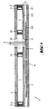
- a construction element 1 is manufactured by the way of insulating glazing from a monolithic window 2, a window composite 3 (laminated glass) as well as a frame-shaped spacer 4 securely joining the two panes 2 and 3 together.
- the latter is glued hermetically in the usual way at the periphery of the two panes 2 and 3 at using an adhesive, for example a butyl glue. He circumscribes the surface lateral of a space 5 comprised between the panes, the main faces of which are formed by the inner sides of the two panes 2 and 3, and it runs at a low distance from the outer edge of the two panes, parallel to their edges.
- the the remaining peripheral groove is filled in the usual way with a sealing mass 4 ', for example polysulphide.
- the composite pane 3 also serves as a carrier pane 6 for elements functional electrical devices 7, here in the form of photovoltaic solar cells. These are arranged in a manner known per se between two panes 3.1 and 3.2 and they are electrically connected in series with each other.
- the space welcoming functional elements between the panes 3.1 and 3.2 is, also so known, filled with a highly hardened molding composition transparent 3.3, which coats the solar cells and constitutes a layer of adhesive assembling the two panes 3.1 and 3.2 inseparably from one another.
- the layer of molding resin is shown here with a thickness exaggerated, to show more clearly the mounting position of the elements 7 and the arrangement of the wire connections.
- the composite glass 3 with the electrical functional elements 7 In the mounting position of the building element 1, in which it is maintained with hooking elements not shown here, by example to a wall or roof construction, the composite glass 3 with the electrical functional elements 7 generally form the outer side, while the monolithic window 2 faces the substructure. In that case application, only the external glass 3.1 of the composite glass 3 must also be as transparent as possible, while panes 3.2 and 2 may have an opaque, tinted or colored coating. In general, we use however for all these panes of clear glass or a synthetic material corresponding.
- the thickness of the space 5 between the panes is approximately 1.5 cm
- the composite glass 3 with the functional elements 7 also has a thickness about 1.5 cm
- the entire construction element 1 has a thickness about 3.5 cm.
- Its surface can vary within wide limits depending on the respective requirements, as well as the number of functional elements electrics incorporated.
- the hanging elements mentioned can be arranged in the surface of the building element (in the form of fasteners punctual) and / or on the edge of it.
- the window 3.2 facing the space 5 between the windows is provided a hole 8 in the region of the rear face of one of the functional elements 7.
- connection wires 9 starting from the functional elements are introduced into the space 5 between the panes from the space intermediate of the composite filled with the molding mass 3.3.
- Hole 8 is closed with the same molding mass 3.3 after drawing the wires 9.
- an annular spacer 10 is fixed between the two panes 2 and 3 of building element 1, in the same way as the spacer frame 4. It forms the lateral face of an interior space 11, in which a on the other hand opens hole 8 and on the other hand, the wires of connection 9 coming out of the composite glass 3.
- the annular interlayer can as such, seal the space 11.
- sealant 4 can again be provided to ensure a seal additional of this annular spacer.
- This provision can be provided in any area of space 5 between the panes, which surrounds by consistent on all sides, radially outward, the interlayer annular.
- connection wires For simplicity, only two connection wires have been shown here. They preferably consist of electrically insulated flat wires. It is also possible, as already mentioned, to introduce into space interior 11 a greater number of connection wires, moving away from the variant shown, and further to install in it other electrical functional elements.
- the interlayer is circular, which however is not necessarily necessary.
- Annular dividers 10 are available in several sizes. The internal diameters available are currently between 3 and 7 cm. If necessary, we could naturally also make larger rings, especially to accommodate other electrical components.
- a drilled hole (milled) 12 which opens into the interior space 11 defined by the annular interlayer 10 and which allows the connection wires 9 to exit from the element of construction 1. If necessary, the entire interior space 11 is filled with a mass sealing not shown here, which represents additional protection against corrosion attacks on the passage of the connecting wires.
- the hole 8, the central axis of the annular interlayer 10 and the drilled hole 12 must not not be arranged concentrically with each other.
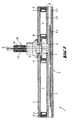
- a metal point fastener 13 indicated only schematically is fixed, as a component additional in the region of the annular interlayer 11, to the element of construction 1 respectively in the drilled hole 12 of the monolithic window 2.
- synthetic intermediate layers prevent the direct contact between the glass (glass) 2 and the material of the point attachment 13.
- Other details of construction thereof and its attachment to the element of construction are primarily interesting only from the point of view of passage of connection wires 9.
- the point attachment can also support in a known manner the two panes 2 and 3, unlike the simplified variant shown here.
- the wires 9 must then possibly be introduced radially therein and continued in the manner shown.
- a through hole 14 extends along from the central axis of the point attachment. It also crosses the articulated area 15 thereof that its rod 16 - provided with an external thread.
- the passage hole 14 is wide enough to receive the connecting wires 9, which are then led outward through the rod 16 of the point attachment 13 and to through the free end of it.
- the wires are sufficiently flexible, to be able to support the compensation movements of the articulated zone 15. The regular amplitude of the movements thereof is by elsewhere too small to be able to damage the connection wires 9, for example example by folding failure.
- the passage of the son of connection 9 inside the point attachment 13 can also describe an angle. We could thus lead the wires certainly in a centered position across the drilled hole 12 inside the point fastener and outwards through the plane of the window 2, and however lead them, on their subsequent journey, radially outwards in a suitable place (for example at the transition between the articulated area and the rod).
- this solution may have advantages compared to the embodiment illustrated in the figure, with regard to the subsequent guidance of the connecting wires in the substructure.
Landscapes
- Engineering & Computer Science (AREA)
- Civil Engineering (AREA)
- Structural Engineering (AREA)
- Architecture (AREA)
- Joining Of Glass To Other Materials (AREA)
- Installation Of Indoor Wiring (AREA)
- Securing Of Glass Panes Or The Like (AREA)
- Photovoltaic Devices (AREA)
- Extrusion Moulding Of Plastics Or The Like (AREA)
- Ropes Or Cables (AREA)
- Manufacturing Of Electric Cables (AREA)
- Panels For Use In Building Construction (AREA)
Priority Applications (1)
| Application Number | Priority Date | Filing Date | Title |
|---|---|---|---|
| DK00403405T DK1106771T3 (da) | 1999-12-07 | 2000-12-05 | Byggeelement med en kabelpassage og fremgangsmåde til fremstilling deraf |
Applications Claiming Priority (2)
| Application Number | Priority Date | Filing Date | Title |
|---|---|---|---|
| DE19958879 | 1999-12-07 | ||
| DE19958879A DE19958879A1 (de) | 1999-12-07 | 1999-12-07 | Bauelement mit einer Leitungsdurchführung |
Publications (3)
| Publication Number | Publication Date |
|---|---|
| EP1106771A2 true EP1106771A2 (de) | 2001-06-13 |
| EP1106771A3 EP1106771A3 (de) | 2002-04-03 |
| EP1106771B1 EP1106771B1 (de) | 2005-03-02 |
Family
ID=7931668
Family Applications (1)
| Application Number | Title | Priority Date | Filing Date |
|---|---|---|---|
| EP00403405A Expired - Lifetime EP1106771B1 (de) | 1999-12-07 | 2000-12-05 | Bauelement mit einer Kabeldurchführung sowie Herstellungsverfahren für dasselbe |
Country Status (6)
| Country | Link |
|---|---|
| EP (1) | EP1106771B1 (de) |
| AT (1) | ATE290151T1 (de) |
| DE (3) | DE29924398U1 (de) |
| DK (1) | DK1106771T3 (de) |
| ES (1) | ES2237397T3 (de) |
| PT (1) | PT1106771E (de) |
Cited By (2)
| Publication number | Priority date | Publication date | Assignee | Title |
|---|---|---|---|---|
| CN104040726A (zh) * | 2011-11-09 | 2014-09-10 | Lg伊诺特有限公司 | 太阳能电池设备 |
| CN108369971A (zh) * | 2015-11-23 | 2018-08-03 | 蒂森克虏伯钢铁欧洲股份公司 | 用于生产功能模块的方法 |
Families Citing this family (12)
| Publication number | Priority date | Publication date | Assignee | Title |
|---|---|---|---|---|
| DE10146498C2 (de) | 2001-09-21 | 2003-11-20 | Arnold Glaswerke | Photovoltaik-Isolierverglasung |
| DE10225140A1 (de) * | 2002-05-29 | 2003-12-11 | Wuerth Solar Gmbh & Co Kg | Solarmodul |
| DE20209970U1 (de) | 2002-06-27 | 2002-09-05 | Kirrlacher Glasmanufaktur Andreas Herzog GmbH, 68753 Waghäusel | Beheizbares Beschattungssystem |
| DE10241728B4 (de) * | 2002-09-10 | 2006-03-16 | Saint-Gobain Glass Deutschland Gmbh | Mehrschichtiges elektrisches beheizbares Flächenelement |
| DE10327752B3 (de) * | 2003-06-10 | 2004-11-04 | Joachim Orbach | Vorrichtung zur Halterung einer Platte |
| DE20218215U1 (de) * | 2002-11-22 | 2004-04-01 | Platz, Karl Otto | Befestigungsmittel für Verbundglasscheiben |
| DE202007002898U1 (de) * | 2007-02-28 | 2008-07-10 | SCHÜCO International KG | Fassaden- oder Lichtdachkonstruktion für ein Gebäude |
| DE102007042028A1 (de) | 2007-09-05 | 2009-03-12 | Saint-Gobain Sekurit Deutschland Gmbh & Co. Kg | Scheibe mit einem Detektor für elektromagnetische Strahlung |
| DE102010002544B3 (de) * | 2010-03-03 | 2011-09-08 | Heinrich Lamparter Stahlbau Gmbh & Co. Kg | Vorhangfassade für ein Gebäude |
| DE102010010871A1 (de) * | 2010-03-10 | 2011-09-15 | Ife Eriksen Ag | Anschlusselement zur Anordnung auf Solarmodulen und Solarmodule |
| EP3117992A1 (de) * | 2015-07-16 | 2017-01-18 | AGC Glass Europe | Glasscheibe mit integrierter elektronischer vorrichtung |
| EP4467910A1 (de) * | 2023-05-25 | 2024-11-27 | Saniku S.A. | Mehrscheiben-isolierglas und verfahren zur herstellung eines mehrscheiben-isolierglases |
Citations (3)
| Publication number | Priority date | Publication date | Assignee | Title |
|---|---|---|---|---|
| DE178292C (de) | ||||
| EP0192472B1 (de) | 1985-02-19 | 1990-05-23 | Pilkington Plc | Abgedichtete Doppelscheibeneinheit |
| DE29509193U1 (de) | 1995-06-02 | 1995-08-17 | Flachglas Solartechnik GmbH, 50667 Köln | Bauelement, insbesondere Fassadenelement |
Family Cites Families (4)
| Publication number | Priority date | Publication date | Assignee | Title |
|---|---|---|---|---|
| DE1278292B (de) * | 1966-05-24 | 1968-09-19 | Niederlassung Vereinigte Glasw | Alarmglasscheibe |
| NL8701747A (nl) * | 1987-07-23 | 1989-02-16 | Buva Bv | Meervoudige glasruit. |
| DE4101277A1 (de) * | 1991-01-17 | 1992-07-23 | Grimm Friedrich Bjoern | Mehrscheiben-isolierverglasung |
| DE29621302U1 (de) * | 1996-12-07 | 1997-02-06 | Schmitt, Horst-Henry, 32756 Detmold | Distanzhalter |
-
1999
- 1999-12-07 DE DE29924398U patent/DE29924398U1/de not_active Expired - Lifetime
- 1999-12-07 DE DE19958879A patent/DE19958879A1/de not_active Withdrawn
-
2000
- 2000-12-05 ES ES00403405T patent/ES2237397T3/es not_active Expired - Lifetime
- 2000-12-05 DK DK00403405T patent/DK1106771T3/da active
- 2000-12-05 AT AT00403405T patent/ATE290151T1/de active
- 2000-12-05 EP EP00403405A patent/EP1106771B1/de not_active Expired - Lifetime
- 2000-12-05 DE DE60018359T patent/DE60018359T2/de not_active Expired - Lifetime
- 2000-12-05 PT PT00403405T patent/PT1106771E/pt unknown
Patent Citations (3)
| Publication number | Priority date | Publication date | Assignee | Title |
|---|---|---|---|---|
| DE178292C (de) | ||||
| EP0192472B1 (de) | 1985-02-19 | 1990-05-23 | Pilkington Plc | Abgedichtete Doppelscheibeneinheit |
| DE29509193U1 (de) | 1995-06-02 | 1995-08-17 | Flachglas Solartechnik GmbH, 50667 Köln | Bauelement, insbesondere Fassadenelement |
Cited By (3)
| Publication number | Priority date | Publication date | Assignee | Title |
|---|---|---|---|---|
| CN104040726A (zh) * | 2011-11-09 | 2014-09-10 | Lg伊诺特有限公司 | 太阳能电池设备 |
| CN108369971A (zh) * | 2015-11-23 | 2018-08-03 | 蒂森克虏伯钢铁欧洲股份公司 | 用于生产功能模块的方法 |
| CN108369971B (zh) * | 2015-11-23 | 2021-03-12 | 蒂森克虏伯钢铁欧洲股份公司 | 用于生产功能模块的方法 |
Also Published As
| Publication number | Publication date |
|---|---|
| DK1106771T3 (da) | 2005-07-04 |
| DE60018359T2 (de) | 2006-01-26 |
| PT1106771E (pt) | 2005-07-29 |
| DE29924398U1 (de) | 2003-02-06 |
| EP1106771B1 (de) | 2005-03-02 |
| ES2237397T3 (es) | 2005-08-01 |
| DE60018359D1 (de) | 2005-04-07 |
| EP1106771A3 (de) | 2002-04-03 |
| DE19958879A1 (de) | 2001-07-05 |
| ATE290151T1 (de) | 2005-03-15 |
Similar Documents
| Publication | Publication Date | Title |
|---|---|---|
| EP1106771B1 (de) | Bauelement mit einer Kabeldurchführung sowie Herstellungsverfahren für dasselbe | |
| EP1537762B1 (de) | Verbindungseinrichtung für ein flächiges element mit mehreren schichten ausgestattet mit elektrischen funktionselementen und flächiges element | |
| EP3303723B1 (de) | Platte, anordnung der platten und zugehöriges dach | |
| CA2931337C (fr) | Panneau, assemblage de panneaux et toiture associee | |
| CA2970212A1 (fr) | Baie vitree isolante | |
| FR2465315A1 (fr) | Panneau generateur photovoltaique assurant l'etancheite aux intemperies d'une toiture par pose directe sur la charpente | |
| WO2015173516A1 (fr) | Ensemble vitre lumineux, porte et meuble réfrigéré avec cet ensemble et fabrication | |
| EP2354718A2 (de) | Integrationsblock für Solarmodul und mit solchen Blocks versehenes Dach | |
| EP3304728B1 (de) | Elektrische verbindungsvorrichtung für ein photovoltaiksystem | |
| FR2985328A1 (fr) | Vitrage multiple a diffusion variable par cristaux liquides | |
| EP4046271A1 (de) | Flache fotovoltaische fliese, installationsverfahren und erzielte abdeckung | |
| EP3347218B1 (de) | Seitliche verglasung eines verkehrsmittels zur befestigung von aussen | |
| EP3129562A1 (de) | Wärmedämmungsanordnung mit piv-platten und verfahren zur montage einer derartigen anordnung | |
| WO2012168659A1 (fr) | Cloison eclairante en verre | |
| EP1109140B1 (de) | Glaselement | |
| FR3068513A1 (fr) | Panneau photovoltaique | |
| WO2012168660A1 (fr) | Cloison eclairante en verre | |
| FR3046296A1 (fr) | Dispositif photovoltaique avec boitier de jonction electrique, procede de fabrication et utilisation dudit dispositif | |
| EP3660257A1 (de) | Verglasungsblock für glastrennwand | |
| FR2948956A1 (fr) | Dispositif pour la pose d'une couverture incluant des panneaux solaires | |
| FR2999205A1 (fr) | Systeme de fixation et d’etancheite pour la realisation d’une toiture solaire comprenant des vitrages electrochromes, et toiture solaire obtenue | |
| FR2781415A1 (fr) | Vitrage feuillete de securite | |
| FR3096998A1 (fr) | Système de fixation pour panneaux sur une toiture étanchéifiée, procédé d’installation | |
| EP2003279A1 (de) | Klappfenster oder Ähnliches mit Rahmen, mit verdecktem Öffnungsflügel | |
| FR3010222A1 (fr) | Structure d'enseigne lumineuse |
Legal Events
| Date | Code | Title | Description |
|---|---|---|---|
| PUAI | Public reference made under article 153(3) epc to a published international application that has entered the european phase |
Free format text: ORIGINAL CODE: 0009012 |
|
| AK | Designated contracting states |
Kind code of ref document: A2 Designated state(s): AT BE CH CY DE DK ES FI FR GB GR IE IT LI LU MC NL PT SE TR |
|
| AX | Request for extension of the european patent |
Free format text: AL;LT;LV;MK;RO;SI |
|
| PUAL | Search report despatched |
Free format text: ORIGINAL CODE: 0009013 |
|
| AK | Designated contracting states |
Kind code of ref document: A3 Designated state(s): AT BE CH CY DE DK ES FI FR GB GR IE IT LI LU MC NL PT SE TR |
|
| AX | Request for extension of the european patent |
Free format text: AL;LT;LV;MK;RO;SI |
|
| 17P | Request for examination filed |
Effective date: 20020411 |
|
| AKX | Designation fees paid |
Free format text: AT BE CH CY DE DK ES FI FR GB GR IE IT LI LU MC NL PT SE TR |
|
| GRAP | Despatch of communication of intention to grant a patent |
Free format text: ORIGINAL CODE: EPIDOSNIGR1 |
|
| GRAS | Grant fee paid |
Free format text: ORIGINAL CODE: EPIDOSNIGR3 |
|
| GRAA | (expected) grant |
Free format text: ORIGINAL CODE: 0009210 |
|
| AK | Designated contracting states |
Kind code of ref document: B1 Designated state(s): AT BE CH CY DE DK ES FI FR GB GR IE IT LI LU MC NL PT SE TR |
|
| PG25 | Lapsed in a contracting state [announced via postgrant information from national office to epo] |
Ref country code: IE Free format text: LAPSE BECAUSE OF FAILURE TO SUBMIT A TRANSLATION OF THE DESCRIPTION OR TO PAY THE FEE WITHIN THE PRESCRIBED TIME-LIMIT Effective date: 20050302 Ref country code: FI Free format text: LAPSE BECAUSE OF FAILURE TO SUBMIT A TRANSLATION OF THE DESCRIPTION OR TO PAY THE FEE WITHIN THE PRESCRIBED TIME-LIMIT Effective date: 20050302 |
|
| REG | Reference to a national code |
Ref country code: GB Ref legal event code: FG4D Free format text: NOT ENGLISH |
|
| REG | Reference to a national code |
Ref country code: CH Ref legal event code: EP |
|
| REG | Reference to a national code |
Ref country code: IE Ref legal event code: FG4D Free format text: FRENCH |
|
| REF | Corresponds to: |
Ref document number: 60018359 Country of ref document: DE Date of ref document: 20050407 Kind code of ref document: P |
|
| REG | Reference to a national code |
Ref country code: SE Ref legal event code: TRGR |
|
| PG25 | Lapsed in a contracting state [announced via postgrant information from national office to epo] |
Ref country code: GR Free format text: LAPSE BECAUSE OF FAILURE TO SUBMIT A TRANSLATION OF THE DESCRIPTION OR TO PAY THE FEE WITHIN THE PRESCRIBED TIME-LIMIT Effective date: 20050602 |
|
| GBT | Gb: translation of ep patent filed (gb section 77(6)(a)/1977) |
Effective date: 20050606 |
|
| REG | Reference to a national code |
Ref country code: DK Ref legal event code: T3 |
|
| REG | Reference to a national code |
Ref country code: PT Ref legal event code: SC4A Effective date: 20050601 |
|
| REG | Reference to a national code |
Ref country code: ES Ref legal event code: FG2A Ref document number: 2237397 Country of ref document: ES Kind code of ref document: T3 |
|
| REG | Reference to a national code |
Ref country code: IE Ref legal event code: FD4D |
|
| PG25 | Lapsed in a contracting state [announced via postgrant information from national office to epo] |
Ref country code: CY Free format text: LAPSE BECAUSE OF FAILURE TO SUBMIT A TRANSLATION OF THE DESCRIPTION OR TO PAY THE FEE WITHIN THE PRESCRIBED TIME-LIMIT Effective date: 20051205 |
|
| PG25 | Lapsed in a contracting state [announced via postgrant information from national office to epo] |
Ref country code: MC Free format text: LAPSE BECAUSE OF NON-PAYMENT OF DUE FEES Effective date: 20051231 |
|
| PLBE | No opposition filed within time limit |
Free format text: ORIGINAL CODE: 0009261 |
|
| STAA | Information on the status of an ep patent application or granted ep patent |
Free format text: STATUS: NO OPPOSITION FILED WITHIN TIME LIMIT |
|
| 26N | No opposition filed |
Effective date: 20051205 |
|
| REG | Reference to a national code |
Ref country code: FR Ref legal event code: PLFP Year of fee payment: 16 |
|
| REG | Reference to a national code |
Ref country code: FR Ref legal event code: PLFP Year of fee payment: 17 |
|
| PGFP | Annual fee paid to national office [announced via postgrant information from national office to epo] |
Ref country code: LU Payment date: 20161216 Year of fee payment: 17 Ref country code: NL Payment date: 20161212 Year of fee payment: 17 Ref country code: DK Payment date: 20161212 Year of fee payment: 17 |
|
| PGFP | Annual fee paid to national office [announced via postgrant information from national office to epo] |
Ref country code: SE Payment date: 20161213 Year of fee payment: 17 Ref country code: ES Payment date: 20161111 Year of fee payment: 17 Ref country code: BE Payment date: 20161221 Year of fee payment: 17 Ref country code: FR Payment date: 20161216 Year of fee payment: 17 Ref country code: PT Payment date: 20161205 Year of fee payment: 17 Ref country code: IT Payment date: 20161221 Year of fee payment: 17 |
|
| PGFP | Annual fee paid to national office [announced via postgrant information from national office to epo] |
Ref country code: DE Payment date: 20171129 Year of fee payment: 18 Ref country code: TR Payment date: 20171205 Year of fee payment: 18 |
|
| PGFP | Annual fee paid to national office [announced via postgrant information from national office to epo] |
Ref country code: GB Payment date: 20171129 Year of fee payment: 18 Ref country code: AT Payment date: 20171128 Year of fee payment: 18 Ref country code: CH Payment date: 20171212 Year of fee payment: 18 |
|
| REG | Reference to a national code |
Ref country code: DK Ref legal event code: EBP Effective date: 20171231 |
|
| PG25 | Lapsed in a contracting state [announced via postgrant information from national office to epo] |
Ref country code: PT Free format text: LAPSE BECAUSE OF NON-PAYMENT OF DUE FEES Effective date: 20180605 |
|
| REG | Reference to a national code |
Ref country code: NL Ref legal event code: MM Effective date: 20180101 |
|
| PG25 | Lapsed in a contracting state [announced via postgrant information from national office to epo] |
Ref country code: SE Free format text: LAPSE BECAUSE OF NON-PAYMENT OF DUE FEES Effective date: 20171206 |
|
| PG25 | Lapsed in a contracting state [announced via postgrant information from national office to epo] |
Ref country code: NL Free format text: LAPSE BECAUSE OF NON-PAYMENT OF DUE FEES Effective date: 20180101 Ref country code: LU Free format text: LAPSE BECAUSE OF NON-PAYMENT OF DUE FEES Effective date: 20171205 |
|
| REG | Reference to a national code |
Ref country code: FR Ref legal event code: ST Effective date: 20180831 |
|
| REG | Reference to a national code |
Ref country code: BE Ref legal event code: MM Effective date: 20171231 |
|
| PG25 | Lapsed in a contracting state [announced via postgrant information from national office to epo] |
Ref country code: IT Free format text: LAPSE BECAUSE OF NON-PAYMENT OF DUE FEES Effective date: 20171205 Ref country code: FR Free format text: LAPSE BECAUSE OF NON-PAYMENT OF DUE FEES Effective date: 20180102 |
|
| PG25 | Lapsed in a contracting state [announced via postgrant information from national office to epo] |
Ref country code: BE Free format text: LAPSE BECAUSE OF NON-PAYMENT OF DUE FEES Effective date: 20171231 |
|
| PG25 | Lapsed in a contracting state [announced via postgrant information from national office to epo] |
Ref country code: DK Free format text: LAPSE BECAUSE OF NON-PAYMENT OF DUE FEES Effective date: 20171231 |
|
| REG | Reference to a national code |
Ref country code: ES Ref legal event code: FD2A Effective date: 20190702 Ref country code: DE Ref legal event code: R119 Ref document number: 60018359 Country of ref document: DE |
|
| PG25 | Lapsed in a contracting state [announced via postgrant information from national office to epo] |
Ref country code: ES Free format text: LAPSE BECAUSE OF NON-PAYMENT OF DUE FEES Effective date: 20171206 |
|
| REG | Reference to a national code |
Ref country code: CH Ref legal event code: PL |
|
| REG | Reference to a national code |
Ref country code: AT Ref legal event code: MM01 Ref document number: 290151 Country of ref document: AT Kind code of ref document: T Effective date: 20181205 |
|
| GBPC | Gb: european patent ceased through non-payment of renewal fee |
Effective date: 20181205 |
|
| PG25 | Lapsed in a contracting state [announced via postgrant information from national office to epo] |
Ref country code: DE Free format text: LAPSE BECAUSE OF NON-PAYMENT OF DUE FEES Effective date: 20190702 |
|
| PG25 | Lapsed in a contracting state [announced via postgrant information from national office to epo] |
Ref country code: LI Free format text: LAPSE BECAUSE OF NON-PAYMENT OF DUE FEES Effective date: 20181231 Ref country code: CH Free format text: LAPSE BECAUSE OF NON-PAYMENT OF DUE FEES Effective date: 20181231 Ref country code: AT Free format text: LAPSE BECAUSE OF NON-PAYMENT OF DUE FEES Effective date: 20181205 Ref country code: GB Free format text: LAPSE BECAUSE OF NON-PAYMENT OF DUE FEES Effective date: 20181205 |
|
| PG25 | Lapsed in a contracting state [announced via postgrant information from national office to epo] |
Ref country code: TR Free format text: LAPSE BECAUSE OF NON-PAYMENT OF DUE FEES Effective date: 20181205 |