EP1106813B1 - Procédé de détermination du débit massique d'un mélange gazeux - Google Patents
Procédé de détermination du débit massique d'un mélange gazeux Download PDFInfo
- Publication number
- EP1106813B1 EP1106813B1 EP00124703A EP00124703A EP1106813B1 EP 1106813 B1 EP1106813 B1 EP 1106813B1 EP 00124703 A EP00124703 A EP 00124703A EP 00124703 A EP00124703 A EP 00124703A EP 1106813 B1 EP1106813 B1 EP 1106813B1
- Authority
- EP
- European Patent Office
- Prior art keywords
- mass flow
- tank ventilation
- max
- intake manifold
- depending
- Prior art date
- Legal status (The legal status is an assumption and is not a legal conclusion. Google has not performed a legal analysis and makes no representation as to the accuracy of the status listed.)
- Expired - Lifetime
Links
- 238000000034 method Methods 0.000 title claims description 10
- 239000000203 mixture Substances 0.000 title claims description 6
- 238000009423 ventilation Methods 0.000 claims description 19
- 238000002485 combustion reaction Methods 0.000 claims description 13
- 230000001419 dependent effect Effects 0.000 claims description 11
- 230000006698 induction Effects 0.000 claims 4
- 101150115672 DPS1 gene Proteins 0.000 description 3
- 101150053419 dps2 gene Proteins 0.000 description 3
- OKTJSMMVPCPJKN-UHFFFAOYSA-N Carbon Chemical compound [C] OKTJSMMVPCPJKN-UHFFFAOYSA-N 0.000 description 2
- 230000004913 activation Effects 0.000 description 2
- 230000015572 biosynthetic process Effects 0.000 description 2
- 238000006243 chemical reaction Methods 0.000 description 2
- 239000000446 fuel Substances 0.000 description 2
- 238000004364 calculation method Methods 0.000 description 1
- 238000011161 development Methods 0.000 description 1
- 230000018109 developmental process Effects 0.000 description 1
- 238000010586 diagram Methods 0.000 description 1
Images

Classifications
-
- F—MECHANICAL ENGINEERING; LIGHTING; HEATING; WEAPONS; BLASTING
- F02—COMBUSTION ENGINES; HOT-GAS OR COMBUSTION-PRODUCT ENGINE PLANTS
- F02M—SUPPLYING COMBUSTION ENGINES IN GENERAL WITH COMBUSTIBLE MIXTURES OR CONSTITUENTS THEREOF
- F02M25/00—Engine-pertinent apparatus for adding non-fuel substances or small quantities of secondary fuel to combustion-air, main fuel or fuel-air mixture
- F02M25/08—Engine-pertinent apparatus for adding non-fuel substances or small quantities of secondary fuel to combustion-air, main fuel or fuel-air mixture adding fuel vapours drawn from engine fuel reservoir
-
- F—MECHANICAL ENGINEERING; LIGHTING; HEATING; WEAPONS; BLASTING
- F02—COMBUSTION ENGINES; HOT-GAS OR COMBUSTION-PRODUCT ENGINE PLANTS
- F02D—CONTROLLING COMBUSTION ENGINES
- F02D41/00—Electrical control of supply of combustible mixture or its constituents
- F02D41/0025—Controlling engines characterised by use of non-liquid fuels, pluralities of fuels, or non-fuel substances added to the combustible mixtures
- F02D41/003—Adding fuel vapours, e.g. drawn from engine fuel reservoir
- F02D41/0045—Estimating, calculating or determining the purging rate, amount, flow or concentration
-
- F—MECHANICAL ENGINEERING; LIGHTING; HEATING; WEAPONS; BLASTING
- F02—COMBUSTION ENGINES; HOT-GAS OR COMBUSTION-PRODUCT ENGINE PLANTS
- F02D—CONTROLLING COMBUSTION ENGINES
- F02D41/00—Electrical control of supply of combustible mixture or its constituents
- F02D41/0025—Controlling engines characterised by use of non-liquid fuels, pluralities of fuels, or non-fuel substances added to the combustible mixtures
- F02D41/003—Adding fuel vapours, e.g. drawn from engine fuel reservoir
- F02D41/0042—Controlling the combustible mixture as a function of the canister purging, e.g. control of injected fuel to compensate for deviation of air fuel ratio when purging
Definitions
- the invention relates to a method for determining the Mass flow of a gas mixture according to the generic term of Claim 1. Such a method is known from the Publication US 5 216 995 known.
- an internal combustion engine is included Tank ventilation system and a method for controlling the Tank vent valve known.
- the control signal of a Tank vent valve is preferably a pulse width modulated signal, its duty cycle and its period or control frequency depending on the operating parameters of the internal combustion engine, such as. B. the Speed, are variably specifiable.
- Evaporated fuel in the tank must not be burned to the environment be delivered. Therefore, the gas mixture of air and evaporated Fuel usually from an activated carbon store through the electronic controllable tank ventilation valve into the intake manifold and further into the Combustion chamber of the internal combustion engine out. Despite this additional Gas mixture supply from the tank ventilation system should not be possible Deviation from the current load and speed-dependent optimal target fuel-air mixture for the combustion process in the cylinders occur. Therefore, a precise knowledge of the mass flow from the Tank ventilation system required.
- a stored in the control unit is complete open tank ventilation valve maximum mass flow depending on current intake manifold vacuum specified.
- the current one Mass flow is determined by an algorithm in the control unit, at one of the coulters depending on the activation time of the tank ventilation valve of straight lines with the control frequency of the control signal and with the maximum mass flow is multiplied.
- the straight lines are through from Slope factors dependent on the intake manifold vacuum and by the Suction pipe vacuum dependent offset values defined.
- the family of straight lines is replaced by a Straight line equation
- the set of straight lines specified by a map.
- the maximum mass flow m ⁇ max through the tank ventilation system is empirically determined at a duty cycle of 100% and stored in the control unit.
- the current to be determined mass flow m ⁇ is related to this maximum mass flow m ⁇ max.
- a standardized mass pulse value m ⁇ ist / m ⁇ max 1 / f is generated that is independent of the drive frequency of the drive signal.
- this mass pulse value m ⁇ ist / m ⁇ max 1 / f is plotted over the activation time T of the tank ventilation valve by a family of straight lines (A, B) which is dependent on the intake manifold vacuum dps.
- A, B the two straight lines A (for a suction pipe negative pressure value dps2) and B (for a suction pipe negative pressure value dps1) are shown only as an example, dps1 being smaller than dps2.
- a large number of straight lines can be specified.
- the respective offset value b (b A , b B ) and the respective gradient factor a (a A , a B ) of the straight line (A, B) depend on the intake manifold vacuum dps (dps1, dps2) as parameters.
- the influence of the intake manifold vacuum on the time behavior of the gas column in the tank ventilation system is taken into account.
- Intake manifold vacuum dps either the sole intake manifold vacuum or also the differential pressure between the intake manifold vacuum and the Ambient pressure is to be understood, which is preferably by means of a Pressure sensor is measured on the intake manifold.
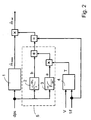
- the intake manifold vacuum or the differential pressure dps is the input signal of a mass flow characteristic 1, an offset characteristic 2 and a gradient characteristic 3.
- the characteristics 1, 2, 3 are determined empirically and stored in the control unit.
- the mass flow characteristic 1 specifies the maximum mass flows m ⁇ max when the tank ventilation valve is fully open, depending on the current intake manifold vacuum dps.
- the offset characteristic b specifies the offset values b (b A , b B ) depending on the intake manifold vacuum dps and the gradient characteristic 3 specifies the gradient factors a (a A , a B ) dependent on the intake manifold vacuum dps.
- the duty cycle V and the period 1 / f of the pulse-width-modulated control signal are input signals of a conversion unit 4.
- the control time T of the tank ventilation valve is determined from the duty cycle V and the period 1 / f.
- the respectively given gradient factor a is multiplied at a first multiplication point by this actuation period T of the tank ventilation valve.
- This product is then added to the respective offset value b at a summing point.
- the output signal of the summing point is divided by the period 1 / f at a quotient formation point.
- the output signal of the quotient formation point is finally multiplied by the maximum mass flow m ⁇ max at a second multiplication point.
- the result is an accurate determination of the required mass flow m ⁇ .
- the accuracy of the method can be optimized by a large number of support points in the characteristic curves.
- the offset characteristic curve 2, the slope characteristic curve 3, the summing point and the first multiplication point are summarized in FIG. 2 as arithmetic unit 5.
- Computing unit 5 also a map representing the family of straight lines be used.
- the method according to the invention is invertible, so that the algorithm can also be used to control the mass flow.
Landscapes
- Engineering & Computer Science (AREA)
- Chemical & Material Sciences (AREA)
- Combustion & Propulsion (AREA)
- Mechanical Engineering (AREA)
- General Engineering & Computer Science (AREA)
- Electrical Control Of Air Or Fuel Supplied To Internal-Combustion Engine (AREA)
- Supplying Secondary Fuel Or The Like To Fuel, Air Or Fuel-Air Mixtures (AREA)
- Combined Controls Of Internal Combustion Engines (AREA)
- Flow Control (AREA)
Claims (3)
- Procédé de détermination du débit massique d'un mélange gazeux, qui est conduit d'une installation de purge du réservoir à la chambre de combustion d'un moteur à combustion interne, au moyen d'un appareil de commande électronique en fonction de la dépression instantanée dans la tubulure d'admission et en fonction du signal de commande de la soupape de purge du réservoir,
caractérisé en ce qu'
un débit massique maximal (m ˙ max) pour la soupape de purge du réservoir entièrement ouverte et mémorisé dans l'appareil de commande est prédéterminé en fonction de la dépression instantanée (dps) dans la tubulure d'admission, et le débit massique instantané (m ˙ ist) est déterminé par un algorithme dans l'appareil de commande, dans lequel un faisceau de droites dépendant du temps de commande (T) de la soupape de purge du réservoir, qui sont définies par des coefficients de pente (a) dépendant de la dépression dans la tubulure d'admission (dps) et par des valeurs de décalage (b) dépendant de la dépression dans la tubulure d'admission (dps), est multiplié par la fréquence de commande (f) du signal de commande et par le débit massique maximal (m ˙ max). - Procédé selon la revendication 1,
caractérisé en ce que
le faisceau de droites est prédéterminé par l'équation des droites (a x T + b), dans laquelleet le coefficient de pente (a) ainsi que la valeur de décalage (b) sont chaque fois prédéterminés par une courbe caractéristique (2, 3) dépendant de la dépression dans la tubulure d'admission.a est le coefficient de pente d'une droiteb est la valeur de décalage d'une droite, etT est le temps de commande du signal de commande, - Procédé selon la revendication 1,
caractérisé en ce que
le faisceau de droites est prédéterminé par un diagramme caractéristique.
Applications Claiming Priority (2)
| Application Number | Priority Date | Filing Date | Title |
|---|---|---|---|
| DE19959660 | 1999-12-10 | ||
| DE19959660A DE19959660C1 (de) | 1999-12-10 | 1999-12-10 | Verfahren zur Bestimmung des Massenstroms eines Gasgemisches |
Publications (3)
| Publication Number | Publication Date |
|---|---|
| EP1106813A2 EP1106813A2 (fr) | 2001-06-13 |
| EP1106813A3 EP1106813A3 (fr) | 2003-05-14 |
| EP1106813B1 true EP1106813B1 (fr) | 2004-03-24 |
Family
ID=7932195
Family Applications (1)
| Application Number | Title | Priority Date | Filing Date |
|---|---|---|---|
| EP00124703A Expired - Lifetime EP1106813B1 (fr) | 1999-12-10 | 2000-11-11 | Procédé de détermination du débit massique d'un mélange gazeux |
Country Status (2)
| Country | Link |
|---|---|
| EP (1) | EP1106813B1 (fr) |
| DE (2) | DE19959660C1 (fr) |
Families Citing this family (5)
| Publication number | Priority date | Publication date | Assignee | Title |
|---|---|---|---|---|
| DE10331581A1 (de) | 2003-07-11 | 2005-01-27 | Robert Bosch Gmbh | Vorrichtung und Verfahren zur Bestimmung des Massenstromes über das Tankentlüftungsventil für eine Verbrennungskraftmaschine |
| DE10335902B4 (de) * | 2003-08-06 | 2015-12-31 | Robert Bosch Gmbh | Verfahren zur Tankentlüftung bei einer Brennkraftmaschine |
| DE102005018272B4 (de) * | 2005-04-20 | 2019-10-31 | Robert Bosch Gmbh | Verfahren und Vorrichtung zum Betreiben einer Brennkraftmaschine |
| DE102017209127A1 (de) * | 2017-05-31 | 2018-12-06 | Robert Bosch Gmbh | Verfahren zum Berechnen eines Massenstroms von einem Tankentlüftungssystem in ein Saugrohr eines Verbrennungsmotors |
| DE102018112487A1 (de) * | 2018-05-24 | 2019-11-28 | Volkswagen Aktiengesellschaft | Verfahren zum Betreiben eines Antriebssystems eines Kraftfahrzeugs, Antriebssystem und Kraftfahrzeug |
Family Cites Families (7)
| Publication number | Priority date | Publication date | Assignee | Title |
|---|---|---|---|---|
| DE3813220C2 (de) * | 1988-04-20 | 1997-03-20 | Bosch Gmbh Robert | Verfahren und Einrichtung zum Stellen eines Tankentlüftungsventiles |
| JPH0533733A (ja) * | 1991-05-20 | 1993-02-09 | Honda Motor Co Ltd | 内燃エンジンの蒸発燃料制御装置 |
| DE4319772A1 (de) * | 1993-06-15 | 1994-12-22 | Bosch Gmbh Robert | Verfahren und Vorrichtung zum Steuern einer Tankentlüftungsanlage |
| JP3154324B2 (ja) * | 1996-05-15 | 2001-04-09 | トヨタ自動車株式会社 | 内燃機関の蒸発燃料処理装置 |
| DE19701353C1 (de) * | 1997-01-16 | 1998-03-12 | Siemens Ag | Verfahren zur Tankentlüftung bei einer Brennkraftmaschine |
| DE19740917B4 (de) * | 1997-04-01 | 2008-11-27 | Robert Bosch Gmbh | Verfahren und Vorrichtung zur Bestimmung der Gastemperatur in einem Verbrennungsmotor |
| DE19756919A1 (de) * | 1997-04-01 | 1998-10-08 | Bosch Gmbh Robert | Verfahren und Vorrichtung zur Bestimmung einer Gasfüllung eines Verbrennungsmotors |
-
1999
- 1999-12-10 DE DE19959660A patent/DE19959660C1/de not_active Expired - Lifetime
-
2000
- 2000-11-11 EP EP00124703A patent/EP1106813B1/fr not_active Expired - Lifetime
- 2000-11-11 DE DE50005783T patent/DE50005783D1/de not_active Expired - Fee Related
Also Published As
| Publication number | Publication date |
|---|---|
| DE50005783D1 (de) | 2004-04-29 |
| DE19959660C1 (de) | 2001-07-05 |
| EP1106813A3 (fr) | 2003-05-14 |
| EP1106813A2 (fr) | 2001-06-13 |
Similar Documents
| Publication | Publication Date | Title |
|---|---|---|
| DE69913091T2 (de) | Vorrichtung zur Steuerung der Ansaugluftmenge eines Verbrennungsmotors mit variabler Ventilsteuerungseinrichtung | |
| DE69530721T2 (de) | System zur Schätzung der Abgasrückführungsrate für einen Verbrennungsmotor | |
| DE3423013C2 (de) | Verfahren zum Steuern eines Bestandteils der Verbrennung in einer Brennkraftmaschine | |
| DE60011382T2 (de) | Brennkraftmaschine mit Bremsanlage | |
| DE102007053319A1 (de) | Anpassung von Ansprechen des Motors beruhend auf Verkehrsbedingungen | |
| DE19545221B4 (de) | Verfahren und Vorrichtung zur Steuerung einer Brennkraftmaschine | |
| DE10219382A1 (de) | Steuerungsvorrichtung für eine Brennkraftmaschine | |
| DE19740916A1 (de) | Verfahren zum Betreiben einer Brennkraftmaschine | |
| EP2276918B1 (fr) | Adaptation d'un moment maximal stationnaire d'un moteur à combustion interne | |
| EP1115964B1 (fr) | Procede pour commander un moteur a combustion interne en fonction d'une pression de gaz d'echappement | |
| EP0286644B1 (fr) | Procede pour determiner electroniquement le debit de carburant d'un moteur a combustion interne | |
| DE102006020675A1 (de) | Verfahren zur Lambda- und Momentenregelung einer Verbrennungskraftmaschine sowie Programmalgorithmus | |
| EP0411321B1 (fr) | Procédé de commande du dosage de carburant dans un moteur diesel | |
| DE69923245T2 (de) | Vorrichtung zur Kraftstoffeinspritzung einer Brennkraftmaschine | |
| DE102005022691A1 (de) | Verfahren und Vorrichtung zum Betreiben einer Brennkraftmaschine | |
| DE19749816B4 (de) | Verfahren zur Ermittlung eines Formfaktors für die Energieumsetzung und Einspritzsystem | |
| EP2162802B1 (fr) | Procédé et dispositif permettant de faire fonctionner un moteur à combustion interne | |
| WO2009033950A2 (fr) | Procédé de régulation d'un processus de combustion et dispositif de combustion | |
| DE19959660C1 (de) | Verfahren zur Bestimmung des Massenstroms eines Gasgemisches | |
| DE19709955A1 (de) | Verfahren und Einrichtung zum Steuern einer Brennkraftmaschine | |
| EP2550443A1 (fr) | Procede et dispositif pour adapter des valeurs d'adaptation pour la commande de soupapes d'injection dans un systeme de moteur avec deux types d'injection | |
| DE10227466A1 (de) | Verfahren und Vorrichtung zum Bestimmen der Zylinderbeladung bei einer Brennkraftmaschine | |
| EP2080885A2 (fr) | Procédé et dispositif destinés à la surveillance d'une unité de commande du moteur | |
| DE102006043679B4 (de) | Verfahren zur Einzelzylinderregelung bei einer Brennkraftmaschine | |
| DE102007021479B4 (de) | Verfahren und Vorrichtung zum Betreiben einer Brennkraftmaschine |
Legal Events
| Date | Code | Title | Description |
|---|---|---|---|
| PUAI | Public reference made under article 153(3) epc to a published international application that has entered the european phase |
Free format text: ORIGINAL CODE: 0009012 |
|
| AK | Designated contracting states |
Kind code of ref document: A2 Designated state(s): AT BE CH CY DE DK ES FI FR GB GR IE IT LI LU MC NL PT SE TR |
|
| AX | Request for extension of the european patent |
Free format text: AL;LT;LV;MK;RO;SI |
|
| PUAL | Search report despatched |
Free format text: ORIGINAL CODE: 0009013 |
|
| AK | Designated contracting states |
Designated state(s): AT BE CH CY DE DK ES FI FR GB GR IE IT LI LU MC NL PT SE TR |
|
| AX | Request for extension of the european patent |
Extension state: AL LT LV MK RO SI |
|
| RIC1 | Information provided on ipc code assigned before grant |
Ipc: 7F 02M 25/08 A Ipc: 7F 02D 41/24 B Ipc: 7F 02D 35/00 B |
|
| GRAP | Despatch of communication of intention to grant a patent |
Free format text: ORIGINAL CODE: EPIDOSNIGR1 |
|
| 17P | Request for examination filed |
Effective date: 20030527 |
|
| GRAS | Grant fee paid |
Free format text: ORIGINAL CODE: EPIDOSNIGR3 |
|
| AKX | Designation fees paid |
Designated state(s): DE FR GB |
|
| GRAA | (expected) grant |
Free format text: ORIGINAL CODE: 0009210 |
|
| AK | Designated contracting states |
Kind code of ref document: B1 Designated state(s): DE FR GB |
|
| REG | Reference to a national code |
Ref country code: GB Ref legal event code: FG4D Free format text: NOT ENGLISH |
|
| GBT | Gb: translation of ep patent filed (gb section 77(6)(a)/1977) |
Effective date: 20040324 |
|
| REG | Reference to a national code |
Ref country code: IE Ref legal event code: FG4D Free format text: GERMAN |
|
| REF | Corresponds to: |
Ref document number: 50005783 Country of ref document: DE Date of ref document: 20040429 Kind code of ref document: P |
|
| REG | Reference to a national code |
Ref country code: IE Ref legal event code: FD4D |
|
| ET | Fr: translation filed | ||
| PLBE | No opposition filed within time limit |
Free format text: ORIGINAL CODE: 0009261 |
|
| STAA | Information on the status of an ep patent application or granted ep patent |
Free format text: STATUS: NO OPPOSITION FILED WITHIN TIME LIMIT |
|
| 26N | No opposition filed |
Effective date: 20041228 |
|
| PGFP | Annual fee paid to national office [announced via postgrant information from national office to epo] |
Ref country code: FR Payment date: 20071129 Year of fee payment: 8 Ref country code: GB Payment date: 20071129 Year of fee payment: 8 |
|
| PGFP | Annual fee paid to national office [announced via postgrant information from national office to epo] |
Ref country code: DE Payment date: 20071214 Year of fee payment: 8 |
|
| GBPC | Gb: european patent ceased through non-payment of renewal fee |
Effective date: 20081111 |
|
| REG | Reference to a national code |
Ref country code: FR Ref legal event code: ST Effective date: 20090731 |
|
| PG25 | Lapsed in a contracting state [announced via postgrant information from national office to epo] |
Ref country code: DE Free format text: LAPSE BECAUSE OF NON-PAYMENT OF DUE FEES Effective date: 20090603 |
|
| PG25 | Lapsed in a contracting state [announced via postgrant information from national office to epo] |
Ref country code: GB Free format text: LAPSE BECAUSE OF NON-PAYMENT OF DUE FEES Effective date: 20081111 |
|
| PG25 | Lapsed in a contracting state [announced via postgrant information from national office to epo] |
Ref country code: FR Free format text: LAPSE BECAUSE OF NON-PAYMENT OF DUE FEES Effective date: 20081130 |