EP1106819A2 - Filter für Druckregelungssystem - Google Patents
Filter für Druckregelungssystem Download PDFInfo
- Publication number
- EP1106819A2 EP1106819A2 EP20000204360 EP00204360A EP1106819A2 EP 1106819 A2 EP1106819 A2 EP 1106819A2 EP 20000204360 EP20000204360 EP 20000204360 EP 00204360 A EP00204360 A EP 00204360A EP 1106819 A2 EP1106819 A2 EP 1106819A2
- Authority
- EP
- European Patent Office
- Prior art keywords
- support
- filter
- filter according
- fuel
- axis
- Prior art date
- Legal status (The legal status is an assumption and is not a legal conclusion. Google has not performed a legal analysis and makes no representation as to the accuracy of the status listed.)
- Granted
Links
Images


Classifications
-
- F—MECHANICAL ENGINEERING; LIGHTING; HEATING; WEAPONS; BLASTING
- F02—COMBUSTION ENGINES; HOT-GAS OR COMBUSTION-PRODUCT ENGINE PLANTS
- F02M—SUPPLYING COMBUSTION ENGINES IN GENERAL WITH COMBUSTIBLE MIXTURES OR CONSTITUENTS THEREOF
- F02M69/00—Low-pressure fuel-injection apparatus ; Apparatus with both continuous and intermittent injection; Apparatus injecting different types of fuel
- F02M69/46—Details, component parts or accessories not provided for in, or of interest apart from, the apparatus covered by groups F02M69/02 - F02M69/44
- F02M69/54—Arrangement of fuel pressure regulators
-
- F—MECHANICAL ENGINEERING; LIGHTING; HEATING; WEAPONS; BLASTING
- F02—COMBUSTION ENGINES; HOT-GAS OR COMBUSTION-PRODUCT ENGINE PLANTS
- F02M—SUPPLYING COMBUSTION ENGINES IN GENERAL WITH COMBUSTIBLE MIXTURES OR CONSTITUENTS THEREOF
- F02M37/00—Apparatus or systems for feeding liquid fuel from storage containers to carburettors or fuel-injection apparatus; Arrangements for purifying liquid fuel specially adapted for, or arranged on, internal-combustion engines
- F02M37/22—Arrangements for purifying liquid fuel specially adapted for, or arranged on, internal-combustion engines, e.g. arrangements in the feeding system
- F02M37/32—Arrangements for purifying liquid fuel specially adapted for, or arranged on, internal-combustion engines, e.g. arrangements in the feeding system characterised by filters or filter arrangements
- F02M37/46—Filters structurally associated with pressure regulators
-
- F—MECHANICAL ENGINEERING; LIGHTING; HEATING; WEAPONS; BLASTING
- F02—COMBUSTION ENGINES; HOT-GAS OR COMBUSTION-PRODUCT ENGINE PLANTS
- F02M—SUPPLYING COMBUSTION ENGINES IN GENERAL WITH COMBUSTIBLE MIXTURES OR CONSTITUENTS THEREOF
- F02M37/00—Apparatus or systems for feeding liquid fuel from storage containers to carburettors or fuel-injection apparatus; Arrangements for purifying liquid fuel specially adapted for, or arranged on, internal-combustion engines
- F02M37/22—Arrangements for purifying liquid fuel specially adapted for, or arranged on, internal-combustion engines, e.g. arrangements in the feeding system
- F02M37/32—Arrangements for purifying liquid fuel specially adapted for, or arranged on, internal-combustion engines, e.g. arrangements in the feeding system characterised by filters or filter arrangements
- F02M37/34—Arrangements for purifying liquid fuel specially adapted for, or arranged on, internal-combustion engines, e.g. arrangements in the feeding system characterised by filters or filter arrangements by the filter structure, e.g. honeycomb, mesh or fibrous
-
- Y—GENERAL TAGGING OF NEW TECHNOLOGICAL DEVELOPMENTS; GENERAL TAGGING OF CROSS-SECTIONAL TECHNOLOGIES SPANNING OVER SEVERAL SECTIONS OF THE IPC; TECHNICAL SUBJECTS COVERED BY FORMER USPC CROSS-REFERENCE ART COLLECTIONS [XRACs] AND DIGESTS
- Y10—TECHNICAL SUBJECTS COVERED BY FORMER USPC
- Y10T—TECHNICAL SUBJECTS COVERED BY FORMER US CLASSIFICATION
- Y10T137/00—Fluid handling
- Y10T137/7722—Line condition change responsive valves
- Y10T137/7781—With separate connected fluid reactor surface
- Y10T137/7834—Valve seat or external sleeve moves to open valve
-
- Y—GENERAL TAGGING OF NEW TECHNOLOGICAL DEVELOPMENTS; GENERAL TAGGING OF CROSS-SECTIONAL TECHNOLOGIES SPANNING OVER SEVERAL SECTIONS OF THE IPC; TECHNICAL SUBJECTS COVERED BY FORMER USPC CROSS-REFERENCE ART COLLECTIONS [XRACs] AND DIGESTS
- Y10—TECHNICAL SUBJECTS COVERED BY FORMER USPC
- Y10T—TECHNICAL SUBJECTS COVERED BY FORMER US CLASSIFICATION
- Y10T137/00—Fluid handling
- Y10T137/794—With means for separating solid material from the fluid
- Y10T137/8122—Planar strainer normal to flow path
Definitions
- a filter for a fuel pressure regulator for automotive fuel systems and more particularly to a filter that is mounted internal to the pressure regulator housing.
- filters have been mounted on an external surface of pressure regulators, and that these external filters are subject to damage and accidental removal during assembly, testing, handling, and installation into a vehicle. It is also believed that filters have been mounted internal to the pressure regulator, and that these internal filters are protected from inadvertent damage and removal, but provide a limited filter area that has proven to be inadequate. It is believed that a fuel filter is needed that is protected from damage and provides a sufficiently large filtration area.
- the present invention provides an internal fuel filter for a pressure regulator that has a body that encloses a fuel flow path.
- the filter comprises a first support that includes a first surface adapted to besealingly surrounded by the body, a second support that is spaced from the first support along an axis, at least one rib that is disposed between and contiguous with the first and second supports, and a filter element that extends between the first support and the second support and surrounds the axis.
- the at least one rib and the second support include a second surface adapted to sealingly surrounded the body.
- the present invention also provides an internal fuel filter for a pressure regulator that has a body that encloses a fuel flow path.
- the filter comprises a first support that includes a first surface adapted to besealingly surrounded by the body, a second support that is spaced from the first support along an axis and includes a second surface adapted tosealingly surrounded the body, at least one rib that is disposed between and contiguous with the first and second supports, and a filter element that extends between the first support and the second support and surrounds the axis.
- the present invention further provides an internal fuel filter for a pressure regulator that has a body that encloses a fuel flow path.
- the filter comprises a first support that includes a first surface adapted to besealingly surrounded by the body, a second support that is spaced from the first support along an axis, at least one rib that is disposed between and contiguous with the first and second supports, and a filter element extends between the first support and the second support and surrounds the axis.
- the at least one rib includes a second surface adapted to sealingly surrounded the body.
- Figure 1A is a side view of a fuel filter according to a first embodiment of the present invention.
- Figure 1B is a top view of the fuel filter shown in Figure 1A.
- Figure 1C is a cross-sectional view of the fuel filter shown in Figure 1A, the cross-section being taken along line 1C-1C in Figure 1B.
- Figure 1D is a cross-sectional view of the fuel filter shown in Figure 1A, the cross-section being taken along line 1D-1D in Figure 1B.
- Figure 2A is a side view of a fuel filter according to a second embodiment of the present invention.
- Figure 2B is a top view of the fuel filter shown in Figure 2A.
- Figure 2C is a cross-sectional view of the fuel filter shown in Figure 2A, the cross-section being taken along line 2C-2C in Figure 2B.
- Figure 2D is a cross-sectional view of the fuel filter shown in Figure 2A, the cross-section being taken along line 2D-2D in Figure 2B.
- Figure 3A is a side view of a fuel filter according to a third embodiment of the present invention.
- Figure 3B is a top view of the fuel filter shown in Figure 3A.
- Figure 3C is a cross-sectional view of the fuel filter shown in Figure 2A, the cross-section being taken along line 3C-3C in Figure 3B.
- Figure 3D is a cross-sectional view of the fuel filter shown in Figure 2A, the cross-section being taken along line 3D-3D in Figure 3B.
- Figure 4 is a cross-sectional view of a flow-through fuel pressure regulator with the fuel filter according to the third embodiment shown on the left side and the fuel filter according to the first embodiment shown on the right side.
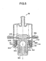
- Figure 5 is a cross-sectional view of a non-flow-through fuel pressure regulator with the fuel filter according to the third embodiment shown on the left side and the fuel filter according to the first embodiment shown on the right side.
- the filter 10 has a first support 102 and a second support 104 offset along a filter axis A.
- the first and second supports 102,104 are connected with ribs 106 to define a filter frame 108.
- a filter element 110 is attached to the frame 108 such that it surrounds the axis A, forming a generally cylindrical filter assembly.
- the frame 108 is substantially fluid-impermeable and the filter element 110 is substantially fluid-permeable.
- the first and second supports 102,104 can be annular.
- the first support 102 has a protrusion 112 on a portion of an inner circumference that can engage a first internal surface of a fuel pressure regulator.
- the protrusion 112 can extend along the entire inner circumference of the first support 102, or can extend along a length of the first support 102 that is contiguous with the ribs 106.
- the second support 104 has a sealing surface 114 on an outer circumference that can engage a second internal surface of a fuel pressure regulator.
- the protrusion 112 and sealing surface 114 create a flow path through at least a portion of the filter element 110 that is substantially perpendicular to the axis A.
- the supports 102,104 and ribs 106 can be made of a thermoplastic material, although other materials are considered to be within the scope of the invention.
- the filter element 110 can be a woven filter material that is insert molded into the frame 108 using a conventional process, thereby sealing the filter element 110 within the supports 102,104 and ribs 106.
- the filter element 110 can be made from a single piece extending over the entire frame circumference, or from multiple pieces extending over acircumferential portion of the frame 108. When multiple pieces are used, the ends can overlap before the insert molding process.
- One or more of the ribs 106 can have an increased circumferential dimension to accommodate overlapping ends of the filter material.
- the ribs 106 have an outer surface 116 oriented obliquely with respect to the filter axis A. The orientation of the outer surfaces 116 can aid in the removal of the filter element 110 from a mold during manufacture.
- FIG. 2A - 2D An alternative filter embodiment 20 is shown in Figures 2A - 2D.
- This embodiment has elements comparable to the first embodiment 10, including a first support 202 and a second support 204 connected with ribs 206 to define a filter frame 208, and a filter element 210 attached to the frame 208 such that it surrounds the axis A.
- the first support 202 has a protrusion 212 on a portion of an inner circumference that can engage a first internal surface of a fuel pressure regulator.
- the protrusion 212 can extend along the entire inner circumference of the first support 202, or can extend along a length of the first support 202 contiguous with the ribs 206.
- the second support 204 has a sealing surface 214 on an outer circumference that can engage a second internal surface of a fuel pressure regulator.
- the protrusion 212 and sealing surface 214 create a flow path through at least a portion of the filter element 210 that is substantially perpendicular to the axis A.
- the ribs 206 have an outer surface 216 that is oriented substantially parallel to the filter axis A. The orientation of the surfaces 216 can result in a lower mold manufacturing cost, since the fuel filter 20 is relatively geometrically simple.
- FIG. 3A - 3D Another alternative filter embodiment 30 is shown in Figures 3A - 3D.
- This embodiment has elements comparable to the other embodiments 10,20, including a first support 302 and a second support 304 connected with ribs 306 to define a filter frame 308, and a filter element 310 attached to the frame 308 such that it surrounds the axis A.
- At least one rib has a protrusion 312 on a portion of an inner circumference that can engage a first internal surface of a fuel pressure regulator.
- the protrusion 312 can extend along the entire inner circumference of the at least one rib 306, or can extend along a portion of a length of the at least one rib 306. Further, protrusions can be disposed on each of the ribs 306.
- the second support 304 has a sealing surface 314 on an outer circumference that can engage a second internal surface of a fuel pressure regulator.
- the protrusion 312 and sealing surface 314 create a flow path through at least a portion of the filter element 310 that is substantially perpendicular to the axis A.
- the ribs 306 have an outer surface 316 that is oriented substantially parallel to the filter axis A. The orientation of the outer surfaces 316 can result in a lower mold manufacturing cost, thereby decreasing the cost of the fuel filter 30.
- FIG 4 shows examples of fuel filters according to the present invention installed in a flow-through fuel pressure regulator 40.
- Fuel filters 10 and 30 are shown for illustrative purposes, although it is understood that a single filter 10, 20, or 30 would be used at any given time. Further, fuel filter 20 would be installed in a similar manner.
- the indentation 418 receives the protrusion or protrusions 112,312, and retains the filter 10,30 in place.
- the protrusion or protrusions 112,312, and sealing surfaces 114,314, define a flow path through the filter 10,30.
- fuel enters the regulator 40 through the openings 410 in the lower housing 412, then passes through the filter element 110,310 in a substantially radial direction (away from axis A) before proceeding through the valve seat 402 and the opening 414 in the upper regulator housing 416.
- FIG. 5 shows an example of the fuel filters of the present invention installed in a non-flow-through fuel pressure regulator 50.
- Fuel filters 10 and 30 are shown for illustrative purposes, although it is understood that a single filter 10, 20, or 30 would be used at any given time. Further, fuel filter 20 would be installed in a similar manner.
- the protrusion 112 on the inner circumference of the first support 102 and the protrusions 312 on the inner circumference of the ribs 306 of the filter 10,30 engage an indentation an indentation 514 on an outer surface of the valve body 506.
- the indentation 514 receives the protrusion or protrusions 112,312 and retains the filter 10,30 in place.
- the sealing surface 114,314 on the outer circumference of the second support 104,304 engages an inner surface of the regulator housing 508.
- the protrusion or protrusions 112,312, and sealing surfacesl 14,314, define a flow path through the filter 10,30.
- fuel enters the valve body 506 through the opening 507 in its lower end, then passes through the valve seat 510 before passing through the filter element 110,310 in a substantially radial direction (towards axis A). The fuel then proceeds out of the regulator 50 through the openings 512 in the lower regulator housing 508.
Landscapes
- Engineering & Computer Science (AREA)
- Chemical & Material Sciences (AREA)
- Combustion & Propulsion (AREA)
- Mechanical Engineering (AREA)
- General Engineering & Computer Science (AREA)
- Filtration Of Liquid (AREA)
- Fuel-Injection Apparatus (AREA)
Applications Claiming Priority (5)
| Application Number | Priority Date | Filing Date | Title |
|---|---|---|---|
| US16874499P | 1999-12-06 | 1999-12-06 | |
| US168744P | 1999-12-06 | ||
| US729717 | 2000-12-06 | ||
| US09/729,717 US6523566B2 (en) | 1999-12-06 | 2000-12-06 | Filter for pressure regulator |
| 2001-02-02 |
Publications (3)
| Publication Number | Publication Date |
|---|---|
| EP1106819A2 true EP1106819A2 (de) | 2001-06-13 |
| EP1106819A3 EP1106819A3 (de) | 2003-03-26 |
| EP1106819B1 EP1106819B1 (de) | 2006-05-10 |
Family
ID=26864411
Family Applications (1)
| Application Number | Title | Priority Date | Filing Date |
|---|---|---|---|
| EP20000204360 Expired - Lifetime EP1106819B1 (de) | 1999-12-06 | 2000-12-06 | Filter für Druckregelungssystem |
Country Status (3)
| Country | Link |
|---|---|
| US (1) | US6523566B2 (de) |
| EP (1) | EP1106819B1 (de) |
| DE (1) | DE60027846T2 (de) |
Cited By (2)
| Publication number | Priority date | Publication date | Assignee | Title |
|---|---|---|---|---|
| EP1308660A3 (de) * | 2001-10-30 | 2003-10-01 | TGK Co., Ltd. | Entspannungsventil |
| FR2856457A1 (fr) * | 2003-06-06 | 2004-12-24 | Siemens Vdo Automotive Corp | Regulateur de pression a bille de valve fixe et son procede d'assemblage |
Families Citing this family (3)
| Publication number | Priority date | Publication date | Assignee | Title |
|---|---|---|---|---|
| KR100854780B1 (ko) * | 2007-02-14 | 2008-08-27 | 주식회사 만도 | 필터 및 이를 포함하는 전자 제어 동력 보조 조향장치의압력 제어 밸브 |
| US20120048237A1 (en) * | 2010-08-31 | 2012-03-01 | Gm Global Technology Operations, Inc. | Fuel pressure regulator |
| JP6665064B2 (ja) * | 2016-09-20 | 2020-03-13 | 愛三工業株式会社 | 圧力調整弁 |
Citations (2)
| Publication number | Priority date | Publication date | Assignee | Title |
|---|---|---|---|---|
| US5413077A (en) | 1994-05-09 | 1995-05-09 | Siemens Automotive L.P. | Non-return fuel system with fuel pressure vacuum response |
| US5509444A (en) | 1995-03-30 | 1996-04-23 | Siemens Automotive Corporation | Flow through pressure regulator |
Family Cites Families (9)
| Publication number | Priority date | Publication date | Assignee | Title |
|---|---|---|---|---|
| US4130622A (en) * | 1977-02-22 | 1978-12-19 | Abbott Laboratories | Method of making self-supporting tubular filter |
| DE2910846A1 (de) * | 1979-03-20 | 1980-10-02 | Bosch Gmbh Robert | Differenzdruckventil fuer eine kraftstoffeinspritzanlage |
| US4310142A (en) * | 1980-03-13 | 1982-01-12 | Tom Mcguane Industries, Inc. | Fuel pressure regulator assembly |
| DE3811002A1 (de) * | 1988-03-31 | 1989-10-19 | Pierburg Gmbh | Elektromagnetisches einspritzventil fuer brennkraftmaschinen |
| DE4037952A1 (de) * | 1990-11-29 | 1992-06-04 | Bosch Gmbh Robert | Verfahren zur montage eines filters an einem ventil und ventil |
| US5078167A (en) * | 1990-12-18 | 1992-01-07 | Parr Manufacturing, Inc. | Fuel filter and pressure regulator system apparatus |
| DE4430471A1 (de) * | 1994-08-27 | 1996-02-29 | Bosch Gmbh Robert | Flüssigkeitsfilter mit eingebautem Druckregler |
| US6098652A (en) * | 1999-01-21 | 2000-08-08 | Parr Manufacturing, Inc. | Quick connect fuel filter and regulator |
| US6334460B1 (en) * | 1999-12-06 | 2002-01-01 | Siemens Automotive Corporation | Pressure regulator baffle seat with radial flow paths |
-
2000
- 2000-12-06 US US09/729,717 patent/US6523566B2/en not_active Expired - Fee Related
- 2000-12-06 EP EP20000204360 patent/EP1106819B1/de not_active Expired - Lifetime
- 2000-12-06 DE DE2000627846 patent/DE60027846T2/de not_active Expired - Lifetime
Patent Citations (2)
| Publication number | Priority date | Publication date | Assignee | Title |
|---|---|---|---|---|
| US5413077A (en) | 1994-05-09 | 1995-05-09 | Siemens Automotive L.P. | Non-return fuel system with fuel pressure vacuum response |
| US5509444A (en) | 1995-03-30 | 1996-04-23 | Siemens Automotive Corporation | Flow through pressure regulator |
Cited By (4)
| Publication number | Priority date | Publication date | Assignee | Title |
|---|---|---|---|---|
| EP1308660A3 (de) * | 2001-10-30 | 2003-10-01 | TGK Co., Ltd. | Entspannungsventil |
| US6712281B2 (en) | 2001-10-30 | 2004-03-30 | Tgk Co. Ltd. | Expansion valve |
| FR2856457A1 (fr) * | 2003-06-06 | 2004-12-24 | Siemens Vdo Automotive Corp | Regulateur de pression a bille de valve fixe et son procede d'assemblage |
| US7040344B2 (en) | 2003-06-06 | 2006-05-09 | Siemens Vdo Automotive Corporation | Pressure regulator including a fixed valve ball and method of assembling the same |
Also Published As
| Publication number | Publication date |
|---|---|
| US6523566B2 (en) | 2003-02-25 |
| DE60027846T2 (de) | 2006-11-30 |
| US20010029928A1 (en) | 2001-10-18 |
| EP1106819B1 (de) | 2006-05-10 |
| DE60027846D1 (de) | 2006-06-14 |
| EP1106819A3 (de) | 2003-03-26 |
Similar Documents
| Publication | Publication Date | Title |
|---|---|---|
| US11633686B2 (en) | Round filter element, in particular for gas filtration | |
| US8758470B2 (en) | Intake air filter for internal combustion engines | |
| EP0755485B1 (de) | In eine kraftstoffverteilerleiste engebauter getrennter filter | |
| US8152876B2 (en) | Filter element having V-seal | |
| US10137390B2 (en) | Filter device, especially liquid filter | |
| US6019128A (en) | Fuel injection valve | |
| JP3119484B2 (ja) | 燃料フィルタ | |
| US6506302B2 (en) | Key system for ecological filter cartridge and element | |
| US6540806B2 (en) | Filter with a cylindrical housing and an annular filter cartridge | |
| US6495042B1 (en) | Filter cartridge for a fuel filter having a keyed latch shut-off valve | |
| CN1122626A (zh) | 装在顶部供油喷油器中的过滤器滤芯 | |
| US20040164017A1 (en) | Filter element with vent orifice and assembly therefore | |
| US12201924B2 (en) | Fuel filter element and filter assembly | |
| CN112118899B (zh) | 具有轻质构造的次级过滤器元件的流体过滤器 | |
| US6655364B1 (en) | Fuel feed device | |
| US4416238A (en) | Fuel injection system | |
| EP1106819A2 (de) | Filter für Druckregelungssystem | |
| US4453671A (en) | Fuel injection system | |
| WO2017155974A1 (en) | Retrofittable no filter no run filtration system | |
| US6955755B2 (en) | Liquid filter comprising a valve arranged in a support tube of a filter element | |
| US6889708B2 (en) | Valve comprising a filter | |
| US9095795B2 (en) | Anti-drainback valve with position positive locking for spin-on oil and fuel filters | |
| US6143046A (en) | Filter cartridge having vibratable diaphragm | |
| WO2019217434A9 (en) | Filter cartridge locking assembly | |
| JPH0642924B2 (ja) | オイルフィルタ装置 |
Legal Events
| Date | Code | Title | Description |
|---|---|---|---|
| PUAI | Public reference made under article 153(3) epc to a published international application that has entered the european phase |
Free format text: ORIGINAL CODE: 0009012 |
|
| AK | Designated contracting states |
Kind code of ref document: A2 Designated state(s): AT BE CH CY DE DK ES FI FR GB GR IE IT LI LU MC NL PT SE TR |
|
| AX | Request for extension of the european patent |
Free format text: AL;LT;LV;MK;RO;SI |
|
| PUAL | Search report despatched |
Free format text: ORIGINAL CODE: 0009013 |
|
| AK | Designated contracting states |
Kind code of ref document: A3 Designated state(s): AT BE CH CY DE DK ES FI FR GB GR IE IT LI LU MC NL PT SE TR |
|
| AX | Request for extension of the european patent |
Extension state: AL LT LV MK RO SI |
|
| RIC1 | Information provided on ipc code assigned before grant |
Ipc: 7F 02M 37/22 A Ipc: 7F 02M 69/54 B |
|
| 17P | Request for examination filed |
Effective date: 20030917 |
|
| RAP1 | Party data changed (applicant data changed or rights of an application transferred) |
Owner name: SIEMENS VDO AUTOMOTIVE CORPORATION |
|
| AKX | Designation fees paid |
Designated state(s): DE FR GB IT |
|
| 17Q | First examination report despatched |
Effective date: 20040429 |
|
| GRAP | Despatch of communication of intention to grant a patent |
Free format text: ORIGINAL CODE: EPIDOSNIGR1 |
|
| GRAS | Grant fee paid |
Free format text: ORIGINAL CODE: EPIDOSNIGR3 |
|
| GRAA | (expected) grant |
Free format text: ORIGINAL CODE: 0009210 |
|
| AK | Designated contracting states |
Kind code of ref document: B1 Designated state(s): DE FR GB IT |
|
| REG | Reference to a national code |
Ref country code: GB Ref legal event code: FG4D |
|
| REF | Corresponds to: |
Ref document number: 60027846 Country of ref document: DE Date of ref document: 20060614 Kind code of ref document: P |
|
| PGFP | Annual fee paid to national office [announced via postgrant information from national office to epo] |
Ref country code: GB Payment date: 20061207 Year of fee payment: 7 |
|
| ET | Fr: translation filed | ||
| PGFP | Annual fee paid to national office [announced via postgrant information from national office to epo] |
Ref country code: FR Payment date: 20061222 Year of fee payment: 7 |
|
| PGFP | Annual fee paid to national office [announced via postgrant information from national office to epo] |
Ref country code: IT Payment date: 20061231 Year of fee payment: 7 |
|
| PLBE | No opposition filed within time limit |
Free format text: ORIGINAL CODE: 0009261 |
|
| STAA | Information on the status of an ep patent application or granted ep patent |
Free format text: STATUS: NO OPPOSITION FILED WITHIN TIME LIMIT |
|
| 26N | No opposition filed |
Effective date: 20070213 |
|
| GBPC | Gb: european patent ceased through non-payment of renewal fee |
Effective date: 20071206 |
|
| REG | Reference to a national code |
Ref country code: FR Ref legal event code: ST Effective date: 20081020 |
|
| PG25 | Lapsed in a contracting state [announced via postgrant information from national office to epo] |
Ref country code: GB Free format text: LAPSE BECAUSE OF NON-PAYMENT OF DUE FEES Effective date: 20071206 |
|
| PG25 | Lapsed in a contracting state [announced via postgrant information from national office to epo] |
Ref country code: FR Free format text: LAPSE BECAUSE OF NON-PAYMENT OF DUE FEES Effective date: 20071231 |
|
| PG25 | Lapsed in a contracting state [announced via postgrant information from national office to epo] |
Ref country code: IT Free format text: LAPSE BECAUSE OF NON-PAYMENT OF DUE FEES Effective date: 20071206 |
|
| PGFP | Annual fee paid to national office [announced via postgrant information from national office to epo] |
Ref country code: DE Payment date: 20121231 Year of fee payment: 13 |
|
| REG | Reference to a national code |
Ref country code: DE Ref legal event code: R119 Ref document number: 60027846 Country of ref document: DE |
|
| REG | Reference to a national code |
Ref country code: DE Ref legal event code: R119 Ref document number: 60027846 Country of ref document: DE Effective date: 20140701 |
|
| PG25 | Lapsed in a contracting state [announced via postgrant information from national office to epo] |
Ref country code: DE Free format text: LAPSE BECAUSE OF NON-PAYMENT OF DUE FEES Effective date: 20140701 |