EP1106881B1 - Soupape de commande de fluide avec un papillon de réglage - Google Patents
Soupape de commande de fluide avec un papillon de réglage Download PDFInfo
- Publication number
- EP1106881B1 EP1106881B1 EP00125351A EP00125351A EP1106881B1 EP 1106881 B1 EP1106881 B1 EP 1106881B1 EP 00125351 A EP00125351 A EP 00125351A EP 00125351 A EP00125351 A EP 00125351A EP 1106881 B1 EP1106881 B1 EP 1106881B1
- Authority
- EP
- European Patent Office
- Prior art keywords
- valve
- passage
- valve body
- annular gasket
- flow control
- Prior art date
- Legal status (The legal status is an assumption and is not a legal conclusion. Google has not performed a legal analysis and makes no representation as to the accuracy of the status listed.)
- Expired - Lifetime
Links
Images
Classifications
-
- F—MECHANICAL ENGINEERING; LIGHTING; HEATING; WEAPONS; BLASTING
- F16—ENGINEERING ELEMENTS AND UNITS; GENERAL MEASURES FOR PRODUCING AND MAINTAINING EFFECTIVE FUNCTIONING OF MACHINES OR INSTALLATIONS; THERMAL INSULATION IN GENERAL
- F16K—VALVES; TAPS; COCKS; ACTUATING-FLOATS; DEVICES FOR VENTING OR AERATING
- F16K27/00—Construction of housing; Use of materials therefor
- F16K27/02—Construction of housing; Use of materials therefor of lift valves
- F16K27/0209—Check valves or pivoted valves
- F16K27/0218—Butterfly valves
Definitions
- the present invention relates to a fluid control valve with butterfly-type flow control element with high operating reliability.
- fluid control valves with a butterfly-type flow control element are generally constituted by a valve body which is formed monolithically and is crossed by a passage which has, on the valve body, an inlet and an outlet which can be connected to the two branches of a duct for a fluid to be controlled by means of the valve.
- the valve body accommodates, in an intermediate region of the passage, a butterfly-type flow control element which can be actuated in order to open or close the passage.
- valve body in an intermediate region of the passage the valve body supports an annular gasket which is fixed to the valve body and can be engaged by the flow control element when it is moved into the closure position.
- the annular gasket is coupled to a circumferential protrusion of the valve body which lies inside the passage and has, in radial cross-section, a dovetail profile.
- connection between the annular gasket and the valve body reduces the actual passage section for the fluid, owing to the fact that the annular gasket necessarily protrudes inside the fluid passage.
- a metal core is provided inside the annular gasket. The presence of the metal core has the drawback that it requires a considerable force in order to close the valve, since it reduces the deformability of the annular gasket and therefore contrasts, with a strong force, the final closure movement and the initial opening movement of the flow control element, i.e., when the flow control element is in contact with the annular gasket.
- valves In order to solve the problem of an excessive reduction of the passage for the fluid inside the valve body, in some valves, particularly in valves designed to be fitted on ducts having a small cross-section, the body is formed in two parts so as to be able to have a duct which has a larger cross-section at the region occupied by the butterfly-type flow control element.
- these valves solve the problem of fluid passage reduction, they still have the drawback of requiring considerable force in order to be able to move the butterfly-type flow control element at the end of the closure movement and at the beginning of the opening movement.
- the gasket instead of being fixed to the valve body, is fitted on the flow control element and protrudes from its perimeter.
- the annular gasket is much more exposed, with respect to the previously cited valves, to the action of the fluid that flows through the valve.
- the action of the fluid produces wear and deformation of the gasket, which can reduce the sealing effect of the gasket when the valve is closed.
- This seepage of fluid has the effect of causing separation of the annular gasket and therefore of reducing or even eliminating the sealing effect of the annular gasket.
- GB-A-2 284 647 discloses a butterfly valve having a combination of features as set forth in the precharacterizing portion of the appended claim 1.
- the aim of the present invention is to solve the above-described problems, by providing a fluid control valve provided with an annular sealing gasket which is associated with the valve body and is designed to cooperate with the butterfly-type flow control element when it is moved into the closure position, and in which the possibility of separation of the annular gasket from the valve body is excluded with absolute safety.
- an object of the invention is to provide a fluid control valve with a butterfly-type flow control element in which the presence of the annular gasket does not reduce excessively, in the open condition, the passage section available to the fluid.
- Another object of the invention is to provide a fluid co0ntrol valve with a butterfly-type flow control element which excludes the possibility of seepage of fluid between the annular gasket and the valve body.
- Another object of the invention is to provide a fluid control valve with a butterfly-type flow control element in which the annular gasket is protected against excessive wear on the part of the butterfly-type flow control element and on the part of the fluid that flows through the valve.
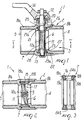
- the fluid control valve comprises a valve body 2 which is crossed by a passage 3 provided with an inlet 4 and with an outlet 5 which can be connected to the two branches of a duct (not shown) for a fluid, particularly a liquid, to be controlled by means of the valve 1.
- the valve body 2 accommodates, in an intermediate region of the passage 3, a butterfly-type flow control element 6 which can be actuated in order to close or open the passage 3.
- the valve body 2 supports an annular gasket, generally designated by the reference numeral 7, which is made of flexible material and can be engaged by the flow control element 6 when it is moved into the closure position.
- valve body 2 is provided in at least two parts 8a and 8b, which are mutually coupled at a region occupied by the annular gasket 7 and lock said annular gasket 7 between them in the mutual coupling position.
- the passage 3 has, at least at the intermediate region occupied by the flow control element 6, a substantially cylindrical shape.
- the flow control element 6 is substantially disk-like and is supported by the valve body 2 so that it can rotate about a diametrical axis 9.
- the flow control element 6 can rotate on command about the diametrical axis 9, with respect to the valve body 2, in order to pass from an open position, in which it is arranged on a plane which passes through the axis of the intermediate region of the passage 3, to a closed position, in which it is arranged on a plane which is substantially perpendicular to the axis of the intermediate region of the passage 3 and engages, with its perimeter, the annular gasket 7.
- the flow control element 6 is crossed by a passage 11 having a splined profile and inside which a pivot 12 is provided having a region 12a with a splined profile that couples to the passage 11.
- the pivot 12 protrudes, with both of its ends, from the perimeter of the flow control element 6.
- One end of the pivot 12 engages a rotation seat 13 provided in the valve body 2, while the other end protrudes from the valve body 2 and can be connected to an actuation lever 14 by means of which it is possible to turn the flow control element 6 about the diametrical axis 9.
- the valve body 2 comprises a first part 8a and a second part 8b which are mutually coupled by means of a threaded coupling whose axis coincides with the axis of the intermediate region of the passage 3.
- the annular gasket 7 is partially accommodated in an annular seat 15 which is formed partly in the first part 8a and partly in the second part 8b of the valve body 2 in the region of mutual coupling.
- the annular seat 15 is open toward the axis of the intermediate region of the passage 3 in order to expose the inner lateral surface of the annular gasket 7 that can be engaged by the flow control element 6.
- the annular seat 15 has regions 15a and 15b which are undercut with respect to a movement toward the axis of the intermediate region of the passage 3 and are engaged by correspondingly shaped regions of the annular gasket 7.
- the annular gasket 7 has an outer lateral surface 16 which is substantially cylindrical and an inner lateral surface which is also substantially cylindrical and has, in an intermediate region of its axial extension, a circumferential protrusion 17 which protrudes toward the axis of the annular gasket 7 and is meant to be engaged by the perimeter of the flow control element 6.
- the annular gasket 7 has, on its two bases, a circumferential raised coupling portion 18a and 18b which protrudes adjacent to the outer lateral surface 16 and can engage the undercut regions 15a and 15b of the annular seat 15.
- the annular gasket 7 has, in the region of its two bases that connect the circumferential coupling protrusions 18a and 18b to the inner lateral surface, circumferential sealing protrusions 19a and 19b which are meant to be compressed at least partially in the coupling of the annular gasket 7 to the annular seat 15.
- the first part 8a of the valve body 2 has, at least proximate to the second part 8b of the valve body 2, a substantially hollow cylindrical configuration which is provided, coaxially on its inner surface and starting from the end that is directed toward the second part 8b, with: a female thread 20, which is engaged by the second part 8b; a substantially cylindrical portion of the annular seat 15, which engages the outer lateral surface 16 of the annular gasket 7; and an axial shoulder 21 with an undercut recess 21a, which axially delimits, on one side, the annular seat 15 and is engaged by the circumferential coupling protrusion 18a provided on one of the bases of the annular gasket 7.
- the second part 8b of the valve body 2 has, at least proximate to the first part 8a of the valve body 2, a substantially hollow cylindrical shape which has, on its outer surface, a male thread 22 which engages the female thread 20 of the first part 8a.
- the second part 8b forms, with its end inserted in the first part 8a, an axial shoulder 23 with an undercut recess 23a which axially delimits, on the other side, the annular seat 15 and is engaged by the circumferential coupling protrusion 18b provided on the other base of the annular gasket 7.
- the pivot 12 passes through diametrical passages 24a and 24b which are formed in the annular gasket 7, in an intermediate region of its axial extension, and a hole 25 which is formed in the first part 8a of the valve body 2.
- the rotation seat 13 is formed in the first part 8a of the valve body 2 in a region which lies diametrically opposite the hole 25.
- the second part 8b further has, on its outer surface, a flange which forms a retention shoulder 26, which can be engaged by the end of the first part 8a that is directed toward the second part 8b and limits the insertion of the second part 8b inside the first part 8a.
- the first part 8a and the second part 8b of the valve body 2 have a substantially cylindrical shape and are coupled coaxially to each other.
- the passage 3 runs coaxially inside the first part 8a and the second part 8b.
- the inlet 4 and the outlet 5 of the passage 3 are threaded internally in order to allow the connection of the two branches of the duct to be controlled by means of the valve, and in the passage 3 there are retention shoulders 27 and 28 for the ends of the branches of the duct that are coupled to the valve body 2.
- the inside diameter of the annular gasket 7a is substantially equal to the diameter of the passage 3.
- the annular gasket 7 is inserted in the first part 8a in the annular seat 15 before assembling the first part 8a and the second part 8b.
- the flow control element 6 is arranged at the annular gasket 7, with the passage 11 in alignment with the diametrical passages 24a and 24b of the annular gasket 7, and the pivot 12 is inserted in the passage 11 so that one end of said pivot 12 engages inside of the rotation seat 13 while the other end protrudes from the valve body 2.
- the second part 8b of the valve body 2 is then assembled to the first part 8a by screwing the male thread 20 into the female thread 22.
- the assembly of the second part 8b with the first part 8a locks the annular gasket 7 inside the annular seat 15.
- the assembly of the second part 8b with the first part 8a causes an axial compression of the annular gasket 7 which engages hermetically the valve body 2 and the pivot 12.
- the assembly of the second part 8b with the first part 8a also compresses the circumferential sealing protrusions 19a and 19b, which in this manner exclude with absolute safety the possibility of seepage of fluid between the annular gasket 7 and the annular seat 15 in which it is accommodated.
- the flow control element 6 In the open position, the flow control element 6 is arranged on a plane which passes through the axis of the passage 3. In this position, the annular gasket 7, being substantially completely accommodated inside the annular seat 15, substantially does not hinder the flow of the fluid along the passage 3.
- the flow control element 6 When the flow control element 6 is moved into the closure position, it is arranged on a plane which is perpendicular to the axis of the passage 3 and engages, with its perimeter, the circumferential protrusion 17. It should be noted that the flow control element 6 engages the circumferential protrusion 17 only proximate to the end of its closure rotation and therefore applies minimal stress to the annular gasket 7 without causing any separation of the annular gasket 7 from the valve body 2. Also by virtue of this fact, the final closure movement and the initial opening movement of the flow control element 6 are facilitated and can be actuated with less force.
- control valve according to the invention fully achieves the intended aim and objects, since it has a high safety against the possibility of abnormal deformations of the annular gasket used to form the seal with the flow control element and against the separation of the annular gasket from the valve body.
- Another advantage of the flow control element according to the invention is that it does not significantly penalize the fluid passage section.
- the materials used may be any according to requirements and to the state of the art.
Landscapes
- Engineering & Computer Science (AREA)
- General Engineering & Computer Science (AREA)
- Mechanical Engineering (AREA)
- Lift Valve (AREA)
- Mechanically-Actuated Valves (AREA)
- Preventing Unauthorised Actuation Of Valves (AREA)
- Check Valves (AREA)
- Fluid-Driven Valves (AREA)
- Valve Housings (AREA)
- Multiple-Way Valves (AREA)
Claims (12)
- Soupape (1) de commande de fluide avec un élément de réglage (6) d'écoulement de type papillon, comprenant un corps de soupape (2) qui est traversé par un passage (3) présentant un orifice d'entrée (4) et un orifice de sortie (5) lesquels peuvent être raccordés à deux branches d'une conduite afin de commander un fluide à l'aide de la soupape (1) ; ledit corps (2) de soupape contenant, dans une région intermédiaire dudit passage (3) un élément de réglage (6) d'écoulement de type papillon lequel peut être activé afin d'ouvrir ou de fermer ledit passage (3) ; ledit corps (2) de soupape supportant, dans ladite région intermédiaire du passage (3), un joint statique annulaire (7) lequel peut être mis en prise avec ledit élément de réglage (6) d'écoulement dans une position de fermeture, ledit corps (2) de soupape se composant d'au moins deux parties (8a, 8b) lesquelles sont mutuellement couplées au niveau d'une région occupée par ledit joint statique annulaire (7) et qui bloque ledit joint statique annulaire (7) entre lesdites parties (8a, 8b) dans une position de couplage mutuel, une première partie (8a) du corps de soupape (2) présentant, au moins à proximité d'une seconde partie (8b) du corps de soupape (2), une forme creuse sensiblement cylindrique laquelle est équipée, de manière coaxiale sur sa surface interne et avec comme origine son extrémité dirigée vers ladite seconde partie (8b) : d'un filet femelle (20), lequel est mis en prise par ladite seconde partie (8b) ; d'une partie sensiblement cylindrique d'un support annulaire (15), lequel met en prise la surface latérale externe dudit joint statique annulaire (7) et un épaulement axial (21) présentant un évidement de dégagement (21a) lequel délimite axialement, sur un côté, ledit support annulaire (15) et est mis en prise par l'une des bases dudit joint statique annulaire (7), ladite seconde partie (8b) dudit corps de soupape (2) présentant, au moins à proximité de ladite première partie (8a) du corps de soupape (2), une forme creuse sensiblement cylindrique laquelle est équipée, sur sa surface externe, d'un filet mâle (22) lequel met en prise le filet femelle (20) de ladite première partie (8a) ; ladite seconde partie (8b) formant, avec son extrémité insérée dans ladite première partie (8a), un épaulement axial (23) présentant un évidement de dégagement (23a) lequel délimite axialement, sur l'autre côté, ledit support annulaire (15) et est mis en prise par l'autre base parmi les bases dudit joint statique annulaire (7), caractérisé en ce qu'un axe diamétrique (9) est formé par un pivot (12) raccordé de manière rigide, dans sa rotation autour dudit axe diamétrique (9), audit élément de réglage (6) d'écoulement ; ledit pivot (12) faisant saillie, avec l'une de ses extrémités, depuis ledit corps (2) et mettant en prise, avec son autre extrémité, un support de rotation (13) formé à l'intérieur dudit corps de soupape (2), ledit joint statique annulaire (7) présentant une surface latérale externe sensiblement cylindrique et une surface latérale interne sensiblement cylindrique et, dans une région intermédiaire de son extension axiale, une protubérance circonférentielle (17) laquelle fait saillie en direction de l'axe du joint statique annulaire (7) et a été conçue pour être mise en prise par le périmètre dudit élément de réglage (6) d'écoulement.
- Soupape (1) selon la revendication 1, caractérisée en ce que ledit passage (3) présente, au moins au niveau de ladite région intermédiaire, une forme sensiblement cylindrique ; ledit élément de réglage (6) d'écoulement possédant une configuration sensiblement de disque et étant pivoté vers ledit corps de soupape (2) autour dudit axe diamétrique (9) ; ledit élément de réglage (6) d'écoulement étant apte à effectuer une rotation à la commande autour dudit axe diamétrique (9) relativement audit corps de soupape (2) afin de passer d'une position d'ouverture, dans laquelle il est disposé sur un plan qui passe à travers l'axe de ladite région intermédiaire du passage (3), à une position de fermeture, dans laquelle il est disposé sur un plan sensiblement perpendiculaire à l'axe de la région intermédiaire dudit passage (3) et met en prise ledit joint statique annulaire (7) avec son périmètre.
- Soupape (1) selon la revendication 2, caractérisée en ce que lesdites deux parties (8a, 8b) du corps de soupape (2) comprennent une première partie (8a) et une seconde partie (8b) lesquelles sont couplées mutuellement à l'aide d'un couplage fileté dont l'axe coïncide avec l'axe de ladite région intermédiaire du passage (3).
- Soupape (1) selon la revendication 3, caractérisée en ce que ledit joint statique annulaire (7) est partiellement situé dans ledit support annulaire (15) lequel est formé partiellement dans ladite première partie (8a) et partiellement dans ladite seconde partie (8b) du corps de soupape (2) dans la région de couplage mutuel ; ledit support annulaire (15) étant ouvert dans le sens de l'axe de ladite région intermédiaire du passage (3) afin d'exposer une surface latérale interne du joint statique annulaire (7) qui peut être mis en prise par ledit élément de réglage (6) d'écoulement.
- Soupape (1) selon la revendication 4, caractérisée en ce que ledit support annulaire (15) possède des régions (15a, 15b) lesquelles sont dégagées, en ce qui concerne un mouvement dans la direction de l'axe de ladite région intermédiaire du passage (3), et sont mis en prise par les régions de forme correspondante dudit joint statique annulaire (7).
- Soupape (1) selon la revendication 1, caractérisée en ce que ledit joint statique annulaire (7) présente, sur ses deux bases, une protubérance circonférentielle de couplage (17) laquelle fait saillie de manière adjacente à la surface latérale externe et peut mettre en prise lesdites régions dégagées (15a, 15b) dudit support annulaire (15)
- Soupape (1) selon la revendication 6, caractérisée en ce que ledit joint statique annulaire (7) présente, dans la région de ses bases qui raccorde lesdites protubérances circonférentielles de couplage (17) à sa surface latérale interne, des protubérances circonférentielles de colmatage (19a, 19b) lesquelles sont conçues pour être comprimées au moins partiellement dans le couplage dudit joint statique annulaire (7) vers ledit support annulaire (15).
- Soupape (1) selon la revendication 1, caractérisée en ce que ledit pivot (12) passe à travers les passages diamétriques (24a, 24b) formés dans ledit joint statique annulaire (7), dans une région intermédiaire de son extension axiale, et à travers un trou (25) formé dans ladite première partie (8a) du corps de soupape (2) ; ledit support de rotation (13) étant formé, dans ladite première partie (8a) de la soupape, dans une région qui s'étend de manière diamétricalement opposée audit trou (25).
- Soupape (1) selon la revendication 3, caractérisée en ce que la seconde partie (8b) est équipée à l'extérieur d'un épaulement de rétention (26) lequel peut mettre en prise ladite première partie (8a) et limite son insertion dans ladite première partie (8a).
- Soupape (1) selon la revendication 3, caractérisée en ce que ladite première partie (8a) et ladite seconde partie (8b) sont sensiblement cylindriques et sont couplées de manière coaxiale l'une à l'autre, ledit passage (3) s'étendant de manière coaxiale à l'intérieur de ladite première partie (8a) et de ladite seconde partie (8b).
- Soupape (1) selon la revendication 1, caractérisée en ce que l'orifice d'entrée (4) et l'orifice de sortie (5) dudit passage (3) sont intérieurement filetés pour le raccordement auxdites branches de la conduite à commander et en ce que dans ledit passage (3) des épaulements de rétention (27, 28) pour l'extrémité des branches de la conduite sont couplés audit corps de soupape (2).
- Soupape (1) selon la revendication 1 caractérisée en ce qu'un diamètre intérieur dudit joint statique annulaire (7) est sensiblement égal au diamètre dudit passage (3).
Applications Claiming Priority (2)
| Application Number | Priority Date | Filing Date | Title |
|---|---|---|---|
| ITMI990738U | 1999-12-09 | ||
| IT1999MI000738U IT246930Y1 (it) | 1999-12-09 | 1999-12-09 | Valvola di intercettazione per fluidi con organo otturatore a farfalla ad elevata affidabilita' di funzionamento |
Publications (3)
| Publication Number | Publication Date |
|---|---|
| EP1106881A2 EP1106881A2 (fr) | 2001-06-13 |
| EP1106881A3 EP1106881A3 (fr) | 2002-07-03 |
| EP1106881B1 true EP1106881B1 (fr) | 2004-11-24 |
Family
ID=11382661
Family Applications (1)
| Application Number | Title | Priority Date | Filing Date |
|---|---|---|---|
| EP00125351A Expired - Lifetime EP1106881B1 (fr) | 1999-12-09 | 2000-11-30 | Soupape de commande de fluide avec un papillon de réglage |
Country Status (6)
| Country | Link |
|---|---|
| US (1) | US6446934B2 (fr) |
| EP (1) | EP1106881B1 (fr) |
| AT (1) | ATE283439T1 (fr) |
| DE (1) | DE60016147T2 (fr) |
| ES (1) | ES2232369T3 (fr) |
| IT (1) | IT246930Y1 (fr) |
Families Citing this family (25)
| Publication number | Priority date | Publication date | Assignee | Title |
|---|---|---|---|---|
| JP2002295273A (ja) * | 2001-01-29 | 2002-10-09 | Denso Corp | インサート成形体およびそれにより形成されたスロットルボディ |
| DE10147333A1 (de) * | 2001-09-26 | 2003-04-24 | Bosch Gmbh Robert | Variantenreduzierte Drosseleinrichtung mit austauschbaren Gehäuseteilen |
| DE10156213A1 (de) * | 2001-11-15 | 2003-06-05 | Siemens Ag | Drosselklappenstutzen |
| US20050188951A1 (en) * | 2004-02-27 | 2005-09-01 | Borgwarner Inc. | Press-fit shaft and method |
| US7032884B2 (en) * | 2004-05-26 | 2006-04-25 | Honeywell International, Inc. | Outflow valve butterfly plate retention pin |
| KR100742690B1 (ko) | 2005-07-18 | 2007-07-25 | (주)씨에프 이엔티 | 양방향 버터플라이 밸브 구조 |
| US7264221B2 (en) * | 2005-09-19 | 2007-09-04 | Yeary & Associates, Inc. | Butterfly valve assembly with improved flow characteristics |
| US9821992B2 (en) * | 2006-03-06 | 2017-11-21 | The Coca-Cola Company | Juice dispensing system |
| CN101466971A (zh) * | 2006-04-28 | 2009-06-24 | Smq集团有限公司 | 蝶阀 |
| JP4434269B2 (ja) * | 2007-11-28 | 2010-03-17 | 株式会社デンソー | 内燃機関の吸気制御装置 |
| DE102007058541A1 (de) * | 2007-12-06 | 2009-06-10 | Robert Bosch Gmbh | Klappenstutzen |
| FR2940390B1 (fr) * | 2008-12-18 | 2016-07-29 | Valeo Systemes De Controle Moteur | Volet d'obturation d'une canalisation d'ecoulement de fluide et procede de formation d'un tel volet |
| US20110073789A1 (en) * | 2009-09-28 | 2011-03-31 | Yeary & Associates, Inc. | Butterfly Valve Flow Control Device |
| TWI404607B (zh) * | 2010-04-08 | 2013-08-11 | Basso Ind Corp | 閥門及其墊圈 |
| BR112012028911A2 (pt) * | 2010-05-14 | 2017-06-13 | Bray Int Inc | conjunto de válula e método de usar a mesma. |
| US20140191147A1 (en) * | 2012-03-02 | 2014-07-10 | David E. Sisk | Aeration butterfly valve |
| DE102012224093B4 (de) * | 2012-12-20 | 2026-02-19 | Schaeffler Technologies AG & Co. KG | Ventilvorrichtung für ein Kraftfahrzeug |
| CA2949129C (fr) | 2014-06-13 | 2020-06-30 | The Procter & Gamble Company | Appareil et procedes de modification de surface keratiniques |
| CA2949118C (fr) | 2014-06-13 | 2019-07-23 | The Procter & Gamble Company | Appareil et procedes de modification de surfaces keratiniques |
| CA2949123C (fr) | 2014-06-13 | 2019-05-14 | The Procter & Gamble Company | Cartouches pour le depot de compositions de traitement sur des surfaces keratiniques |
| US9924875B2 (en) | 2014-06-13 | 2018-03-27 | The Procter & Gamble Company | Apparatus and methods for modifying keratinous surfaces |
| US9949552B2 (en) | 2014-07-25 | 2018-04-24 | The Procter & Gamble Company | Handheld treatment apparatus for modifying keratinous surfaces |
| US9955769B2 (en) | 2014-07-25 | 2018-05-01 | The Procter & Gamble Company | Applicator heads for handheld treatment apparatus for modifying keratinous surfaces |
| US9903496B2 (en) * | 2015-05-29 | 2018-02-27 | Mueller International, Llc | Lining for mechanical joints |
| US11116302B2 (en) | 2015-06-11 | 2021-09-14 | The Procter & Gamble Company | Apparatus and methods for modifying keratinous surfaces |
Family Cites Families (19)
| Publication number | Priority date | Publication date | Assignee | Title |
|---|---|---|---|---|
| CA695037A (en) * | 1964-09-29 | Gesellschaft Der Ludw. Von Roll'schen Eisenwerke Ag. | Method and means for sealing relatively movable members | |
| US3025035A (en) * | 1954-02-16 | 1962-03-13 | Swain Frank Edward | Valve |
| DE1022437B (de) * | 1954-12-03 | 1958-01-09 | Frank Edward Swain | Sitzring fuer Drosselklappen |
| GB953981A (en) * | 1962-02-02 | 1964-04-02 | Frank Edward Swain | Improvements in butterfly valves |
| US3250510A (en) * | 1964-02-18 | 1966-05-10 | Crane Co | Self-adjustable seats for butterfly valves or the like |
| US3550905A (en) * | 1969-04-08 | 1970-12-29 | United Aircraft Corp | Valve seal |
| GB1299508A (en) * | 1970-10-29 | 1972-12-13 | Giulio Poliuto Tormene | Butterfly valve |
| US3986699A (en) * | 1974-07-02 | 1976-10-19 | Posi-Seal International, Inc. | Positive shut-off seal |
| DE2750892A1 (de) * | 1977-11-14 | 1979-05-17 | Betonkeramik Gmbh | Stossfugenverschluss fuer rohre |
| US4289296A (en) * | 1979-03-23 | 1981-09-15 | Xomox Corporation | Bidirectional axially pliant pressure assisted seat for a valve |
| JPS56134672A (en) * | 1980-03-25 | 1981-10-21 | Fuji Kinzoku Kosaku Kk | Ball valve |
| DE8015672U1 (de) * | 1980-06-13 | 1980-09-18 | Vorwerk & Co Interholding Gmbh, 5600 Wuppertal | Dichtungsanordnung fuer rohrstuecke an bodenpflegegeraeten |
| US4398695A (en) * | 1981-12-29 | 1983-08-16 | Mcc Flowseal | Metal seal structure |
| SE456112C (sv) * | 1987-01-02 | 1996-04-29 | Somas Ventiler | Vridspjällsventil |
| IT1227297B (it) * | 1988-10-06 | 1991-04-05 | Cazzaniga Spa | Valvola a farfalla con elemento di tenuta in materiale elastomerico dotato di rinforzo metallico interno |
| GB2284647A (en) * | 1993-11-30 | 1995-06-14 | Sigeval S A | Butterfly valve |
| JP3356511B2 (ja) * | 1993-12-01 | 2002-12-16 | 株式会社オーケーエム | バタフライバルブ |
| US5419530A (en) * | 1994-02-16 | 1995-05-30 | Teknocraft, Inc. | Micrometer-controlled linear flow rate fluid flow valve assembly |
| JP2651124B2 (ja) * | 1994-10-14 | 1997-09-10 | 株式会社巴技術研究所 | シートリング及び該シートリングをはめ込んだバタフライ弁 |
-
1999
- 1999-12-09 IT IT1999MI000738U patent/IT246930Y1/it active
-
2000
- 2000-11-30 AT AT00125351T patent/ATE283439T1/de not_active IP Right Cessation
- 2000-11-30 DE DE60016147T patent/DE60016147T2/de not_active Expired - Lifetime
- 2000-11-30 ES ES00125351T patent/ES2232369T3/es not_active Expired - Lifetime
- 2000-11-30 EP EP00125351A patent/EP1106881B1/fr not_active Expired - Lifetime
- 2000-12-01 US US09/726,407 patent/US6446934B2/en not_active Expired - Lifetime
Also Published As
| Publication number | Publication date |
|---|---|
| ATE283439T1 (de) | 2004-12-15 |
| US6446934B2 (en) | 2002-09-10 |
| DE60016147T2 (de) | 2005-04-21 |
| EP1106881A2 (fr) | 2001-06-13 |
| ITMI990738V0 (it) | 1999-12-09 |
| US20010003357A1 (en) | 2001-06-14 |
| ES2232369T3 (es) | 2005-06-01 |
| IT246930Y1 (it) | 2002-04-10 |
| ITMI990738U1 (it) | 2001-06-09 |
| DE60016147D1 (de) | 2004-12-30 |
| EP1106881A3 (fr) | 2002-07-03 |
Similar Documents
| Publication | Publication Date | Title |
|---|---|---|
| EP1106881B1 (fr) | Soupape de commande de fluide avec un papillon de réglage | |
| RU1794223C (ru) | Клапан | |
| EP3904733B1 (fr) | Soupape de régulation de débit | |
| US4738277A (en) | Improvement in rotatable taps | |
| US7232107B2 (en) | Control valve having a filter screen mounted flush with a valve closure member surface | |
| EP1024324B1 (fr) | Dispositif d'accouplement entre un corps de vanne ou similaire et un élément de connection | |
| US4314581A (en) | Rotary valve washerless cartridge | |
| KR830002827B1 (ko) | 혼합밸브 | |
| US4659061A (en) | Seal ring shutoff stem tip | |
| JP2024091675A (ja) | バルブ | |
| US11428326B2 (en) | Centric butterfly valve | |
| US7309058B2 (en) | Flexible backseat seal for gate valve | |
| US20030089875A1 (en) | Control valve stem split guide bushing | |
| EP0708285B1 (fr) | Soupape sanitaire | |
| CN118030880A (zh) | 按键阀及其使用方法 | |
| US6863085B2 (en) | Faucet manifold assembly with in-line integral stops | |
| CN111365472B (zh) | 在线维护的阀门 | |
| EP0237612B1 (fr) | Joint d'étanchéité pour tige guide destiné aux soupapes lubrifiées et muni de boisseaux | |
| EP0974020B1 (fr) | Robinet d'etranglement | |
| CN212338204U (zh) | 在线维护的阀门 | |
| KR200334647Y1 (ko) | 세그먼트 플러그형 메탈시트 볼밸브 | |
| KR200338623Y1 (ko) | 더블 사이드 세그먼트 플러그형 메탈시트 볼밸브 | |
| KR200379158Y1 (ko) | 폴리우레탄 코팅층 제수밸브 | |
| CN220910538U (zh) | 一种带有锁定装置的隔膜阀 | |
| KR200245424Y1 (ko) | 직동식 솔레노이드 밸브체 |
Legal Events
| Date | Code | Title | Description |
|---|---|---|---|
| PUAI | Public reference made under article 153(3) epc to a published international application that has entered the european phase |
Free format text: ORIGINAL CODE: 0009012 |
|
| AK | Designated contracting states |
Kind code of ref document: A2 Designated state(s): AT BE CH CY DE DK ES FI FR GB GR IE IT LI LU MC NL PT SE TR |
|
| AX | Request for extension of the european patent |
Free format text: AL;LT;LV;MK;RO;SI |
|
| PUAL | Search report despatched |
Free format text: ORIGINAL CODE: 0009013 |
|
| AK | Designated contracting states |
Kind code of ref document: A3 Designated state(s): AT BE CH CY DE DK ES FI FR GB GR IE IT LI LU MC NL PT SE TR |
|
| AX | Request for extension of the european patent |
Free format text: AL;LT;LV;MK;RO;SI |
|
| 17P | Request for examination filed |
Effective date: 20021220 |
|
| AKX | Designation fees paid |
Designated state(s): AT BE CH CY DE DK ES FI FR GB GR IE IT LI LU MC NL PT SE TR |
|
| 17Q | First examination report despatched |
Effective date: 20030407 |
|
| GRAP | Despatch of communication of intention to grant a patent |
Free format text: ORIGINAL CODE: EPIDOSNIGR1 |
|
| GRAS | Grant fee paid |
Free format text: ORIGINAL CODE: EPIDOSNIGR3 |
|
| GRAA | (expected) grant |
Free format text: ORIGINAL CODE: 0009210 |
|
| AK | Designated contracting states |
Kind code of ref document: B1 Designated state(s): AT BE CH CY DE DK ES FI FR GB GR IE IT LI LU MC NL PT SE TR |
|
| PG25 | Lapsed in a contracting state [announced via postgrant information from national office to epo] |
Ref country code: CY Free format text: LAPSE BECAUSE OF FAILURE TO SUBMIT A TRANSLATION OF THE DESCRIPTION OR TO PAY THE FEE WITHIN THE PRESCRIBED TIME-LIMIT Effective date: 20041124 Ref country code: NL Free format text: LAPSE BECAUSE OF FAILURE TO SUBMIT A TRANSLATION OF THE DESCRIPTION OR TO PAY THE FEE WITHIN THE PRESCRIBED TIME-LIMIT Effective date: 20041124 Ref country code: LI Free format text: LAPSE BECAUSE OF FAILURE TO SUBMIT A TRANSLATION OF THE DESCRIPTION OR TO PAY THE FEE WITHIN THE PRESCRIBED TIME-LIMIT Effective date: 20041124 Ref country code: CH Free format text: LAPSE BECAUSE OF FAILURE TO SUBMIT A TRANSLATION OF THE DESCRIPTION OR TO PAY THE FEE WITHIN THE PRESCRIBED TIME-LIMIT Effective date: 20041124 Ref country code: AT Free format text: LAPSE BECAUSE OF FAILURE TO SUBMIT A TRANSLATION OF THE DESCRIPTION OR TO PAY THE FEE WITHIN THE PRESCRIBED TIME-LIMIT Effective date: 20041124 Ref country code: SE Free format text: LAPSE BECAUSE OF FAILURE TO SUBMIT A TRANSLATION OF THE DESCRIPTION OR TO PAY THE FEE WITHIN THE PRESCRIBED TIME-LIMIT Effective date: 20041124 Ref country code: FI Free format text: LAPSE BECAUSE OF FAILURE TO SUBMIT A TRANSLATION OF THE DESCRIPTION OR TO PAY THE FEE WITHIN THE PRESCRIBED TIME-LIMIT Effective date: 20041124 Ref country code: TR Free format text: LAPSE BECAUSE OF FAILURE TO SUBMIT A TRANSLATION OF THE DESCRIPTION OR TO PAY THE FEE WITHIN THE PRESCRIBED TIME-LIMIT Effective date: 20041124 Ref country code: FR Free format text: LAPSE BECAUSE OF FAILURE TO SUBMIT A TRANSLATION OF THE DESCRIPTION OR TO PAY THE FEE WITHIN THE PRESCRIBED TIME-LIMIT Effective date: 20041124 Ref country code: BE Free format text: LAPSE BECAUSE OF FAILURE TO SUBMIT A TRANSLATION OF THE DESCRIPTION OR TO PAY THE FEE WITHIN THE PRESCRIBED TIME-LIMIT Effective date: 20041124 |
|
| REG | Reference to a national code |
Ref country code: GB Ref legal event code: FG4D |
|
| PG25 | Lapsed in a contracting state [announced via postgrant information from national office to epo] |
Ref country code: MC Free format text: LAPSE BECAUSE OF NON-PAYMENT OF DUE FEES Effective date: 20041130 Ref country code: IE Free format text: LAPSE BECAUSE OF NON-PAYMENT OF DUE FEES Effective date: 20041130 |
|
| REG | Reference to a national code |
Ref country code: CH Ref legal event code: EP |
|
| REF | Corresponds to: |
Ref document number: 60016147 Country of ref document: DE Date of ref document: 20041230 Kind code of ref document: P |
|
| REG | Reference to a national code |
Ref country code: IE Ref legal event code: FG4D |
|
| PG25 | Lapsed in a contracting state [announced via postgrant information from national office to epo] |
Ref country code: LU Free format text: LAPSE BECAUSE OF NON-PAYMENT OF DUE FEES Effective date: 20050124 |
|
| PG25 | Lapsed in a contracting state [announced via postgrant information from national office to epo] |
Ref country code: GB Free format text: LAPSE BECAUSE OF NON-PAYMENT OF DUE FEES Effective date: 20050224 Ref country code: GR Free format text: LAPSE BECAUSE OF FAILURE TO SUBMIT A TRANSLATION OF THE DESCRIPTION OR TO PAY THE FEE WITHIN THE PRESCRIBED TIME-LIMIT Effective date: 20050224 Ref country code: DK Free format text: LAPSE BECAUSE OF FAILURE TO SUBMIT A TRANSLATION OF THE DESCRIPTION OR TO PAY THE FEE WITHIN THE PRESCRIBED TIME-LIMIT Effective date: 20050224 |
|
| NLV1 | Nl: lapsed or annulled due to failure to fulfill the requirements of art. 29p and 29m of the patents act | ||
| REG | Reference to a national code |
Ref country code: CH Ref legal event code: PL |
|
| REG | Reference to a national code |
Ref country code: ES Ref legal event code: FG2A Ref document number: 2232369 Country of ref document: ES Kind code of ref document: T3 |
|
| REG | Reference to a national code |
Ref country code: IE Ref legal event code: MM4A |
|
| PLBE | No opposition filed within time limit |
Free format text: ORIGINAL CODE: 0009261 |
|
| STAA | Information on the status of an ep patent application or granted ep patent |
Free format text: STATUS: NO OPPOSITION FILED WITHIN TIME LIMIT |
|
| GBPC | Gb: european patent ceased through non-payment of renewal fee |
Effective date: 20050223 |
|
| 26N | No opposition filed |
Effective date: 20050825 |
|
| EN | Fr: translation not filed | ||
| PG25 | Lapsed in a contracting state [announced via postgrant information from national office to epo] |
Ref country code: PT Free format text: LAPSE BECAUSE OF NON-PAYMENT OF DUE FEES Effective date: 20050424 |
|
| PG25 | Lapsed in a contracting state [announced via postgrant information from national office to epo] |
Ref country code: IT Free format text: LAPSE BECAUSE OF NON-PAYMENT OF DUE FEES Effective date: 20071130 |
|
| PGFP | Annual fee paid to national office [announced via postgrant information from national office to epo] |
Ref country code: IT Payment date: 20190912 Year of fee payment: 20 |
|
| PGFP | Annual fee paid to national office [announced via postgrant information from national office to epo] |
Ref country code: DE Payment date: 20191128 Year of fee payment: 20 |
|
| PGFP | Annual fee paid to national office [announced via postgrant information from national office to epo] |
Ref country code: ES Payment date: 20200123 Year of fee payment: 20 |
|
| REG | Reference to a national code |
Ref country code: DE Ref legal event code: R071 Ref document number: 60016147 Country of ref document: DE |
|
| REG | Reference to a national code |
Ref country code: ES Ref legal event code: FD2A Effective date: 20211203 |
|
| PG25 | Lapsed in a contracting state [announced via postgrant information from national office to epo] |
Ref country code: ES Free format text: LAPSE BECAUSE OF EXPIRATION OF PROTECTION Effective date: 20201201 |