EP1106885A2 - Procédé et dispositif pour monter une garniture intérieure dans une structure en terre - Google Patents
Procédé et dispositif pour monter une garniture intérieure dans une structure en terre Download PDFInfo
- Publication number
- EP1106885A2 EP1106885A2 EP00890361A EP00890361A EP1106885A2 EP 1106885 A2 EP1106885 A2 EP 1106885A2 EP 00890361 A EP00890361 A EP 00890361A EP 00890361 A EP00890361 A EP 00890361A EP 1106885 A2 EP1106885 A2 EP 1106885A2
- Authority
- EP
- European Patent Office
- Prior art keywords
- inliner
- centering
- already installed
- clamping
- centering device
- Prior art date
- Legal status (The legal status is an assumption and is not a legal conclusion. Google has not performed a legal analysis and makes no representation as to the accuracy of the status listed.)
- Withdrawn
Links
- 238000000034 method Methods 0.000 title claims abstract description 20
- 238000006073 displacement reaction Methods 0.000 claims 1
- 238000009412 basement excavation Methods 0.000 abstract 1
- 238000009434 installation Methods 0.000 description 4
- 238000009418 renovation Methods 0.000 description 3
- 238000007796 conventional method Methods 0.000 description 1
- 230000007547 defect Effects 0.000 description 1
- 238000005553 drilling Methods 0.000 description 1
- 238000000227 grinding Methods 0.000 description 1
- 238000002347 injection Methods 0.000 description 1
- 239000007924 injection Substances 0.000 description 1
- 238000003801 milling Methods 0.000 description 1
- 238000003825 pressing Methods 0.000 description 1
- 230000005855 radiation Effects 0.000 description 1
- 229920005989 resin Polymers 0.000 description 1
- 239000011347 resin Substances 0.000 description 1
- 230000000007 visual effect Effects 0.000 description 1
- 238000003466 welding Methods 0.000 description 1
Images



Classifications
-
- F—MECHANICAL ENGINEERING; LIGHTING; HEATING; WEAPONS; BLASTING
- F16—ENGINEERING ELEMENTS AND UNITS; GENERAL MEASURES FOR PRODUCING AND MAINTAINING EFFECTIVE FUNCTIONING OF MACHINES OR INSTALLATIONS; THERMAL INSULATION IN GENERAL
- F16L—PIPES; JOINTS OR FITTINGS FOR PIPES; SUPPORTS FOR PIPES, CABLES OR PROTECTIVE TUBING; MEANS FOR THERMAL INSULATION IN GENERAL
- F16L55/00—Devices or appurtenances for use in, or in connection with, pipes or pipe systems
- F16L55/16—Devices for covering leaks in pipes or hoses, e.g. hose-menders
- F16L55/162—Devices for covering leaks in pipes or hoses, e.g. hose-menders from inside the pipe
- F16L55/165—Devices for covering leaks in pipes or hoses, e.g. hose-menders from inside the pipe a pipe or flexible liner being inserted in the damaged section
- F16L55/1652—Devices for covering leaks in pipes or hoses, e.g. hose-menders from inside the pipe a pipe or flexible liner being inserted in the damaged section the flexible liner being pulled into the damaged section
- F16L55/1653—Devices for covering leaks in pipes or hoses, e.g. hose-menders from inside the pipe a pipe or flexible liner being inserted in the damaged section the flexible liner being pulled into the damaged section and being pressed into contact with the pipe by a tool which moves inside along the pipe
-
- F—MECHANICAL ENGINEERING; LIGHTING; HEATING; WEAPONS; BLASTING
- F16—ENGINEERING ELEMENTS AND UNITS; GENERAL MEASURES FOR PRODUCING AND MAINTAINING EFFECTIVE FUNCTIONING OF MACHINES OR INSTALLATIONS; THERMAL INSULATION IN GENERAL
- F16L—PIPES; JOINTS OR FITTINGS FOR PIPES; SUPPORTS FOR PIPES, CABLES OR PROTECTIVE TUBING; MEANS FOR THERMAL INSULATION IN GENERAL
- F16L2101/00—Uses or applications of pigs or moles
- F16L2101/10—Treating the inside of pipes
- F16L2101/18—Lining other than coating
Definitions
- the present invention relates to a method for mounting an inliner on a Already installed inliner in an earth structure, the inliner on a Transport device mounted on rollers to the already installed inliner is moved and pressed against it.
- DE 42 06 623 A1 describes a tubular vehicle for the Internal processing of laid pipe strings known, which is at least one Chassis with several driven wheels and one arranged on it Has tool holding device.
- the bearing bodies of the drive wheels are radial adjustable to adapt the vehicle to different inside diameters can.
- the tool holding device is around a running in the direction of travel Swiveling axis and adjustable in the direction of the pipe wall.
- the pipe vehicle is used to prepare underground pipes for a pipe renovation to be carried out subsequently. To prepare a visual check of the condition using a television camera, drilling, Milling, grinding and welding processes as well as the injection of curable Resins in defects.
- the subsequent pipe renovation is done by lining with a hose-like structure, the hose after pulling in inflated into the pipeline by compressed air and by means of a radiation source is cured.
- such vehicles are for the installation of dimensionally stable inliners not suitable.
- the device consists of two hydraulic clamping cylinders operable pipe gripping pliers, which sit on the pipe surface Jockey wheels are provided.
- the pipe grippers are made by a telescopic Guide crossbar connected and can be operated by hydraulically operated Pull cylinders are pulled together.
- the device is only for Pipes of smaller diameter are suitable, inside which no work is done can.
- From US 5,129,761 A is a method and an apparatus for installing Pipe sections in an earthwork known in which the individual pipe sections can be transported on rails to the laying point.
- the actual laying machine is located inside the pipes and is intended to be installed Bring the pipe to the last pipe already installed. there the laying machine is supported on the one hand in the already laid pipe and on the other hand at the bottom of the earthworks in which the pipes are to be laid. It turned out to be difficult in this way, on the one hand the necessary ones to provide high contact pressures to create a tight connection and on the other hand an exact angular alignment of the pipes to ensure. This alignment becomes more difficult the more uneven is the inner surface of the earth structure in which the pipes are to be laid.
- DE 35 31 648 A describes a method for inserting a tube known in the muffer-shaped end of another tube, which is essentially a cylindrical guide body is inserted into a tube to the Sliding on the other pipe easier.
- the required contact pressure In any case, this method must be applied from the outside.
- the object of the present invention is to provide a method which Avoids the above disadvantages and where it is possible in particular, also large dimensioned and therefore heavy inliners to move safely, the manual Workload should be less than with conventional methods.
- this object is achieved in that first the centering device is firmly connected to an inliner by tensioning devices, then the distance between the inliner to be installed and the already installed inliner is reduced, after which further clamping devices of the centering device are fixed to be connected to the other inliner and that after that the distance between the tensioning devices is reduced until the inliner to be fitted is fixed on the already installed inliner.
- the transport device can be self-propelled or also by Cables are moved, which is a preferred variant of the invention Represents procedure.
- the invention further relates to a device for attaching an inliner to one already installed inliner according to claim 6.
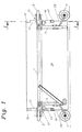
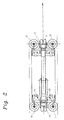
- the transport device consists of a side member 1, that in the immediate vicinity of its end faces 10, 11 each have a star carrier 2, 3 has, on each of which at least three height-adjustable rollers 4, 5, 6, 7, 8, 9 are attached. At least directly on the two end faces 10, 11 two, but preferably three stamps 12, 13, 14, 15, 16, 17, which on their End faces each have a support plate 18, 19, 20, 21, 22, 23, which partially encompass the edges 24, 25 of the inliner 26.
- the longitudinal beam 1 is equipped such that its length changed and thus to the length of the inliner to be transported can be customized.
- the stamps 12 to 17 can also be changed their length adapted to different cross-sectional profiles of the inliner 26 become.
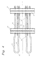
- the centering device according to the invention consists of two clamping devices in the form of clamping frames 27, 28, which, as can be seen from FIG. 4, each can be designed as a double frame. Between these clamping frames 27 and 28 there are several pulling devices 29 which are used to reduce the distance serve between the tenter 27 and 28. Are on the tenter 27 several centering brackets distributed over the inner circumference of the clamping frame 27 30 permanently mounted.
- the scope of the clamping frame 27 and 28 is in each case by Devices 31 changed so that the tenter in the tensioned state are pressed firmly against the inside of the liner, or in a relaxed state detached from the inside of the liner.
- the facilities 31 are as well the pulling devices 29 in preferred variants as spindles or designed as electrically, hydraulically or pneumatically operated devices.
- the U-shaped centering brackets 30 each have a section on their legs 32, 33 34, 35 on that between the U-shaped curvature 36 and the clamping ring 28 lies and is resiliently bent outwards.
- the curvature 36 is approximately in bent to the same extent again. This configuration ensures a self-centering alignment of one pushed onto the centering bracket 30 Inliners.
- the inward curvatures 36 facilitate this Put off.
- This additional equipment 37 and 38 can e.g. Be rubber bands.
- 6 shows the transport an inliner 26 to an already offset inliner 26a.
- Fig. 8 shows a position after retracting the wheels 7, 8 in the to be moved Inliner 26 for another pushing on the already relocated To enable inliners 26a.
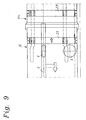
- Fig. 9 ultimately shows the inliner 26 in the offset state, which by the Clamping rings 27 and 28 has been brought into its position. After that the two clamping rings 27 and 28 from the inner walls of the inliner 26th and 26a released and pulled out together with the transport device to to enable the installation of the next inliner.
Landscapes
- Engineering & Computer Science (AREA)
- General Engineering & Computer Science (AREA)
- Mechanical Engineering (AREA)
- Lining And Supports For Tunnels (AREA)
- Tunnel Furnaces (AREA)
Applications Claiming Priority (2)
| Application Number | Priority Date | Filing Date | Title |
|---|---|---|---|
| AT206899 | 1999-12-09 | ||
| AT206899A AT409891B (de) | 1999-12-09 | 1999-12-09 | Verfahren und vorrichtungen zum einbau eines inliners in erdbauwerke |
Publications (2)
| Publication Number | Publication Date |
|---|---|
| EP1106885A2 true EP1106885A2 (fr) | 2001-06-13 |
| EP1106885A3 EP1106885A3 (fr) | 2002-07-24 |
Family
ID=3527098
Family Applications (1)
| Application Number | Title | Priority Date | Filing Date |
|---|---|---|---|
| EP00890361A Withdrawn EP1106885A3 (fr) | 1999-12-09 | 2000-11-30 | Procédé et dispositif pour monter une garniture intérieure dans une structure en terre |
Country Status (2)
| Country | Link |
|---|---|
| EP (1) | EP1106885A3 (fr) |
| AT (1) | AT409891B (fr) |
Cited By (2)
| Publication number | Priority date | Publication date | Assignee | Title |
|---|---|---|---|---|
| ITPR20100069A1 (it) * | 2010-08-24 | 2012-02-25 | Guazzi S N C | Metodo e dispositivo per infilare condotte in micro tunnel sotterranei |
| CN118188881A (zh) * | 2024-03-07 | 2024-06-14 | 广东省源天工程有限公司 | 一种预应力钢筒混凝土管施工用混凝土基座 |
Families Citing this family (1)
| Publication number | Priority date | Publication date | Assignee | Title |
|---|---|---|---|---|
| DE102010014963A1 (de) * | 2010-04-14 | 2011-10-20 | Rbs Spezialmaschinen Gmbh | Vorrichtung und Verfahren zum Einziehen von Rohren in einem Kanal |
Citations (5)
| Publication number | Priority date | Publication date | Assignee | Title |
|---|---|---|---|---|
| DE2200296A1 (de) | 1972-01-05 | 1973-07-26 | Wayss & Freytag Ag | Verfahren und vorrichtung zum verlegen von rohren |
| DE3531648A1 (de) | 1985-09-05 | 1987-03-12 | Hermann Grundhoefer | Verfahren zum einschieben eines endes eines rohres in das muffenartige ende eines anderen rohres sowie fuehrungskoerper zur durchfuehrung des verfahrens |
| DE3610836A1 (de) | 1986-04-01 | 1987-10-08 | Gressbach Winden Und Maschinen | Vorrichtung zum aneinanderfuegen von rohren |
| US5129761A (en) | 1991-03-26 | 1992-07-14 | Constructors Engineering Co., Inc. | Pipe placement method and apparatus |
| DE4206623A1 (de) | 1992-03-03 | 1993-09-09 | Rainer Hitzel | Rohrfahrzeug fuer die innenbearbeitung von verlegten rohrleitungen |
Family Cites Families (2)
| Publication number | Priority date | Publication date | Assignee | Title |
|---|---|---|---|---|
| US3833996A (en) * | 1972-07-14 | 1974-09-10 | J Steiger | Method and a machine for aligning and joining pipes |
| DE3404724A1 (de) * | 1984-02-10 | 1985-09-05 | Louis Georges Cambrai Martinez | Vorrichtung zum schaeften von rohren grossen durchmessers |
-
1999
- 1999-12-09 AT AT206899A patent/AT409891B/de not_active IP Right Cessation
-
2000
- 2000-11-30 EP EP00890361A patent/EP1106885A3/fr not_active Withdrawn
Patent Citations (5)
| Publication number | Priority date | Publication date | Assignee | Title |
|---|---|---|---|---|
| DE2200296A1 (de) | 1972-01-05 | 1973-07-26 | Wayss & Freytag Ag | Verfahren und vorrichtung zum verlegen von rohren |
| DE3531648A1 (de) | 1985-09-05 | 1987-03-12 | Hermann Grundhoefer | Verfahren zum einschieben eines endes eines rohres in das muffenartige ende eines anderen rohres sowie fuehrungskoerper zur durchfuehrung des verfahrens |
| DE3610836A1 (de) | 1986-04-01 | 1987-10-08 | Gressbach Winden Und Maschinen | Vorrichtung zum aneinanderfuegen von rohren |
| US5129761A (en) | 1991-03-26 | 1992-07-14 | Constructors Engineering Co., Inc. | Pipe placement method and apparatus |
| DE4206623A1 (de) | 1992-03-03 | 1993-09-09 | Rainer Hitzel | Rohrfahrzeug fuer die innenbearbeitung von verlegten rohrleitungen |
Cited By (3)
| Publication number | Priority date | Publication date | Assignee | Title |
|---|---|---|---|---|
| ITPR20100069A1 (it) * | 2010-08-24 | 2012-02-25 | Guazzi S N C | Metodo e dispositivo per infilare condotte in micro tunnel sotterranei |
| EP2423559A1 (fr) * | 2010-08-24 | 2012-02-29 | Guazzi S.N.C. Di Guazzi Roberto, Giuliano e Stefano Guazzi | Procédé et dispositif de zone d'entrée de conduites de micro-tunnels souterrains |
| CN118188881A (zh) * | 2024-03-07 | 2024-06-14 | 广东省源天工程有限公司 | 一种预应力钢筒混凝土管施工用混凝土基座 |
Also Published As
| Publication number | Publication date |
|---|---|
| EP1106885A3 (fr) | 2002-07-24 |
| AT409891B (de) | 2002-12-27 |
| ATA206899A (de) | 2002-04-15 |
Similar Documents
| Publication | Publication Date | Title |
|---|---|---|
| EP0158042B1 (fr) | Dispositif pour incorporer des tuyaux en matière plastique dans des égouts | |
| EP0808436B1 (fr) | Procede d'extraction d'un objet creux enterre | |
| DE3610836C2 (de) | Vorrichtung zum Aneinanderfügen von Rohren | |
| DE3928342C2 (fr) | ||
| DE2844490A1 (de) | Verfahren zum behandeln und transportieren von rohren und rohrabschnitten unter wasser sowie rahmen zur durchfuehrung des verfahrens | |
| DE3730315A1 (de) | Verfahren und vorrichtung zum sanieren von kanalrohren | |
| DE4417076C2 (de) | Vorrichtung zum Abdichten von Kanalwandungen im Bereich des Anschlusses eines Nebenkanals an einen Hauptkanal | |
| DE19843263A1 (de) | Verfahren zum Verlegen von Verlegeobjekten in Kanälen, Vorrichtung zur Durchführung des Verfahrens sowie Mittel zur Verwendung bei dem Verfahren | |
| EP1106885A2 (fr) | Procédé et dispositif pour monter une garniture intérieure dans une structure en terre | |
| DE102004043383B4 (de) | Inversionsschleuse mit einer Schleusenkammer | |
| DE19702649A1 (de) | Vorrichtung zur Sanierung von Kanalrohren | |
| DE202008011794U1 (de) | Vorrichtung zum Befestigen eines Rangierhilfsmotors am Fahrgestell eines Fahrzeuganhängers | |
| EP1006638B1 (fr) | Méthode pour la pose souterraine de cables et de lignes d'alimentation | |
| DE3603238A1 (de) | Verfahren zur erneuerung von abwasserleitungen und vorrichtung zur durchfuehrung des verfahrens | |
| DE19717746C2 (de) | Vorrichtung zum Sanieren eines in einen Abwassersammler einmündenden Seiteneinlaufs oder dergleichen | |
| DE19511295A1 (de) | Vorrichtung zum Reparieren einer nicht begehbaren Rohrleitungs-Verzweigung oder Rohrleitungs-Einmündung | |
| DE102006033753B4 (de) | System und Verfahren zum Spannen von Strangabschnitten zu einem Strang | |
| DE9407899U1 (de) | Vorrichtung zum Reparieren unterirdisch verlegter Rohrleitungen | |
| DE3835901A1 (de) | Verfahren zum austausch einer im erdboden verlegten rohrleitung | |
| DE102010004097B4 (de) | Verfahren zum Sanieren eines Altrohrs sowie System zur Durchführung eines solchen Verfahrens | |
| CH684360A5 (de) | Vorrichtung und Verfahren zur Sanierung von Hausanschlussleitungen an nicht begehbaren Abwassersammelleitungen. | |
| DE4418330C2 (de) | Verfahren und Vorrichtung zum Ausbessern der Wandungen im Anschlußbereich eines Zweigleitungsrohres an ein Hauptleitungsrohr | |
| DE19900229A1 (de) | Verfahren und Vorrichtung zum Auskleiden von Kanälen | |
| DE202006014341U1 (de) | Vorrichtung zum Verschweißen zweier Rohre | |
| DE19861090A1 (de) | Verfahren zum Verlegen von Verlegeobjekten in Kanälen, Vorrichtung zur Durchführung des Verfahrens, Verlegeroboter zur Durchführung des Verfahrens, sowie verlegtes Verlegeobjekt |
Legal Events
| Date | Code | Title | Description |
|---|---|---|---|
| PUAI | Public reference made under article 153(3) epc to a published international application that has entered the european phase |
Free format text: ORIGINAL CODE: 0009012 |
|
| AK | Designated contracting states |
Kind code of ref document: A2 Designated state(s): AT BE CH CY DE DK ES FI FR GB GR IE IT LI LU MC NL PT SE TR |
|
| AX | Request for extension of the european patent |
Free format text: AL;LT;LV;MK;RO;SI |
|
| PUAL | Search report despatched |
Free format text: ORIGINAL CODE: 0009013 |
|
| AK | Designated contracting states |
Kind code of ref document: A3 Designated state(s): AT BE CH CY DE DK ES FI FR GB GR IE IT LI LU MC NL PT SE TR |
|
| AX | Request for extension of the european patent |
Free format text: AL;LT;LV;MK;RO;SI |
|
| RIC1 | Information provided on ipc code assigned before grant |
Free format text: 7F 16L 1/06 A, 7F 16L 55/162 B, 7F 16L 1/036 B, 7F 16L 1/10 B |
|
| 17P | Request for examination filed |
Effective date: 20020902 |
|
| AKX | Designation fees paid |
Designated state(s): AT BE CH CY DE DK ES FI FR GB GR IE IT LI LU MC NL PT SE TR |
|
| 17Q | First examination report despatched |
Effective date: 20040202 |
|
| STAA | Information on the status of an ep patent application or granted ep patent |
Free format text: STATUS: THE APPLICATION IS DEEMED TO BE WITHDRAWN |
|
| 18D | Application deemed to be withdrawn |
Effective date: 20040615 |