EP1106932A2 - Porte de four avec éléments de support en matière plastique - Google Patents
Porte de four avec éléments de support en matière plastique Download PDFInfo
- Publication number
- EP1106932A2 EP1106932A2 EP00117908A EP00117908A EP1106932A2 EP 1106932 A2 EP1106932 A2 EP 1106932A2 EP 00117908 A EP00117908 A EP 00117908A EP 00117908 A EP00117908 A EP 00117908A EP 1106932 A2 EP1106932 A2 EP 1106932A2
- Authority
- EP
- European Patent Office
- Prior art keywords
- door
- pane
- elements
- door according
- carrier
- Prior art date
- Legal status (The legal status is an assumption and is not a legal conclusion. Google has not performed a legal analysis and makes no representation as to the accuracy of the status listed.)
- Granted
Links
- 239000000463 material Substances 0.000 title claims description 14
- 229920003023 plastic Polymers 0.000 title abstract description 20
- 239000004033 plastic Substances 0.000 title abstract description 19
- 125000006850 spacer group Chemical group 0.000 claims abstract description 55
- 239000002861 polymer material Substances 0.000 claims description 9
- 230000001427 coherent effect Effects 0.000 claims description 8
- 238000003780 insertion Methods 0.000 claims description 8
- 230000037431 insertion Effects 0.000 claims description 8
- 239000000853 adhesive Substances 0.000 claims description 7
- 230000001070 adhesive effect Effects 0.000 claims description 7
- 238000010411 cooking Methods 0.000 claims description 7
- 239000011521 glass Substances 0.000 claims description 6
- 238000000465 moulding Methods 0.000 claims description 6
- 229920001169 thermoplastic Polymers 0.000 claims description 3
- 229920001187 thermosetting polymer Polymers 0.000 claims description 3
- 239000004416 thermosoftening plastic Substances 0.000 claims description 3
- 238000002347 injection Methods 0.000 claims description 2
- 239000007924 injection Substances 0.000 claims description 2
- 239000012780 transparent material Substances 0.000 claims description 2
- 239000004634 thermosetting polymer Substances 0.000 claims 1
- -1 Polyoxymethylen Polymers 0.000 description 13
- 229920000642 polymer Polymers 0.000 description 6
- 229920006324 polyoxymethylene Polymers 0.000 description 6
- 229920001577 copolymer Polymers 0.000 description 5
- 239000004642 Polyimide Substances 0.000 description 4
- 229920000265 Polyparaphenylene Polymers 0.000 description 4
- 229920006260 polyaryletherketone Polymers 0.000 description 4
- 229920001721 polyimide Polymers 0.000 description 4
- 239000004734 Polyphenylene sulfide Substances 0.000 description 3
- 238000004140 cleaning Methods 0.000 description 3
- 238000013461 design Methods 0.000 description 3
- 238000004519 manufacturing process Methods 0.000 description 3
- 238000000034 method Methods 0.000 description 3
- 229920000069 polyphenylene sulfide Polymers 0.000 description 3
- 239000012791 sliding layer Substances 0.000 description 3
- CBCKQZAAMUWICA-UHFFFAOYSA-N 1,4-phenylenediamine Chemical compound NC1=CC=C(N)C=C1 CBCKQZAAMUWICA-UHFFFAOYSA-N 0.000 description 2
- 244000043261 Hevea brasiliensis Species 0.000 description 2
- 229930182556 Polyacetal Natural products 0.000 description 2
- 239000004952 Polyamide Substances 0.000 description 2
- QQONPFPTGQHPMA-UHFFFAOYSA-N Propene Chemical compound CC=C QQONPFPTGQHPMA-UHFFFAOYSA-N 0.000 description 2
- 229910000831 Steel Inorganic materials 0.000 description 2
- 150000001875 compounds Chemical class 0.000 description 2
- 238000013016 damping Methods 0.000 description 2
- 239000000945 filler Substances 0.000 description 2
- 238000001746 injection moulding Methods 0.000 description 2
- 238000009434 installation Methods 0.000 description 2
- 239000002184 metal Substances 0.000 description 2
- 238000012986 modification Methods 0.000 description 2
- 230000004048 modification Effects 0.000 description 2
- 229920003052 natural elastomer Polymers 0.000 description 2
- 229920001194 natural rubber Polymers 0.000 description 2
- 238000004023 plastic welding Methods 0.000 description 2
- 229920002647 polyamide Polymers 0.000 description 2
- 229920001296 polysiloxane Polymers 0.000 description 2
- 238000003825 pressing Methods 0.000 description 2
- 238000007493 shaping process Methods 0.000 description 2
- 239000010959 steel Substances 0.000 description 2
- 238000012549 training Methods 0.000 description 2
- 229920002943 EPDM rubber Polymers 0.000 description 1
- 229930040373 Paraformaldehyde Natural products 0.000 description 1
- 239000004696 Poly ether ether ketone Substances 0.000 description 1
- 239000004809 Teflon Substances 0.000 description 1
- 229920006362 Teflon® Polymers 0.000 description 1
- 229920006222 acrylic ester polymer Polymers 0.000 description 1
- 238000004026 adhesive bonding Methods 0.000 description 1
- 230000009286 beneficial effect Effects 0.000 description 1
- 230000015572 biosynthetic process Effects 0.000 description 1
- 229910052799 carbon Inorganic materials 0.000 description 1
- YACLQRRMGMJLJV-UHFFFAOYSA-N chloroprene Chemical compound ClC(=C)C=C YACLQRRMGMJLJV-UHFFFAOYSA-N 0.000 description 1
- 239000011248 coating agent Substances 0.000 description 1
- 238000000576 coating method Methods 0.000 description 1
- 239000004020 conductor Substances 0.000 description 1
- 238000001816 cooling Methods 0.000 description 1
- 230000001419 dependent effect Effects 0.000 description 1
- 238000011161 development Methods 0.000 description 1
- 230000018109 developmental process Effects 0.000 description 1
- 238000007688 edging Methods 0.000 description 1
- 230000005489 elastic deformation Effects 0.000 description 1
- 239000013013 elastic material Substances 0.000 description 1
- 229920001971 elastomer Polymers 0.000 description 1
- 239000000806 elastomer Substances 0.000 description 1
- RTZKZFJDLAIYFH-UHFFFAOYSA-N ether Substances CCOCC RTZKZFJDLAIYFH-UHFFFAOYSA-N 0.000 description 1
- NBVXSUQYWXRMNV-UHFFFAOYSA-N fluoromethane Chemical compound FC NBVXSUQYWXRMNV-UHFFFAOYSA-N 0.000 description 1
- 229920002313 fluoropolymer Polymers 0.000 description 1
- 239000003365 glass fiber Substances 0.000 description 1
- 239000002241 glass-ceramic Substances 0.000 description 1
- 230000005484 gravity Effects 0.000 description 1
- 150000008282 halocarbons Chemical class 0.000 description 1
- 239000012212 insulator Substances 0.000 description 1
- 230000010354 integration Effects 0.000 description 1
- 150000002576 ketones Chemical class 0.000 description 1
- 239000000203 mixture Substances 0.000 description 1
- 230000003287 optical effect Effects 0.000 description 1
- 230000002085 persistent effect Effects 0.000 description 1
- 229920000090 poly(aryl ether) Polymers 0.000 description 1
- 229920001200 poly(ethylene-vinyl acetate) Polymers 0.000 description 1
- 229920002530 polyetherether ketone Polymers 0.000 description 1
- 229920001343 polytetrafluoroethylene Polymers 0.000 description 1
- 239000004810 polytetrafluoroethylene Substances 0.000 description 1
- 125000004805 propylene group Chemical group [H]C([H])([H])C([H])([*:1])C([H])([H])[*:2] 0.000 description 1
- 230000035939 shock Effects 0.000 description 1
- 239000007787 solid Substances 0.000 description 1
- 238000003860 storage Methods 0.000 description 1
- 239000000725 suspension Substances 0.000 description 1
- BFKJFAAPBSQJPD-UHFFFAOYSA-N tetrafluoroethene Chemical group FC(F)=C(F)F BFKJFAAPBSQJPD-UHFFFAOYSA-N 0.000 description 1
- 238000003856 thermoforming Methods 0.000 description 1
Images


Classifications
-
- F—MECHANICAL ENGINEERING; LIGHTING; HEATING; WEAPONS; BLASTING
- F24—HEATING; RANGES; VENTILATING
- F24C—DOMESTIC STOVES OR RANGES ; DETAILS OF DOMESTIC STOVES OR RANGES, OF GENERAL APPLICATION
- F24C15/00—Details
- F24C15/02—Doors specially adapted for stoves or ranges
- F24C15/04—Doors specially adapted for stoves or ranges with transparent panels
Definitions
- the invention relates to a door for a cooking oven.
- Doors for household ovens are known with a viewing window, that through a translucent outer pane and a translucent inner pane and possibly also a translucent washer arranged between them is formed.
- DE 197 38 504 C1 discloses a door for a household appliance, in particular a domestic oven, with a door pane that can be installed and removed.
- This known door comprises an outer pane to which two columnar support elements made of an enameled steel sheet formed into a profile part are fastened, and an inner pane which is held removably by two receiving devices fastened to the support elements.
- a spring element is provided in one of the two receiving devices, the other receiving device comprises two corner brackets, each provided for a corner of the inner pane, with a circumferential receiving groove.
- the inner pane Due to the restoring force of the spring element, the inner pane is pressed into the receiving groove of the second receiving device and held there (locked, fixed). To remove the inner pane is simply pressed against the restoring force of the spring element until it emerges from the grooves, and can then be easily removed from the door. In the installed position, the inner pane rests on the flat middle parts of the two column-like support elements and is pushed along these middle parts during assembly or disassembly.
- DE 197 05 120 A1 discloses a door for closing an oven muffle of an oven with a frame-like, circumferential carrier (door frame) made of plastic for enclosing an inner pane, an outer pane and an intermediate pane.
- the frame-like carrier comprises a frame-like filler plate and lateral edging strips which form a frame wall which borders a door interior.
- the frame wall and the filler plate form an integral frame profile part of the frame-like carrier.
- a bracket is glued to the outer pane by means of an adhesive, to which the frame profile part is fastened by means of a screw.
- the inner pane is glued to a support surface of the frame profile part facing away from the outer pane.
- a spacer element which extends into the interior of the door and has a support surface, is formed on the frame profile part.
- the washer rests on one side on the contact surface of the spacer element. On the opposite side, the washer rests on the retaining washer on the outer pane via an elastic element.
- the intermediate pane is clamped between the support surface of the spacer and the elastic element.
- an elastic element can also be arranged on the support surface provided for the outer pane and on the support surface provided for the intermediate pane.
- the inner pane of this oven door known from DE 197 05 120 A1 cannot be removed.
- the invention has for its object a special To specify a door for a cooking oven, preferably for the household, which is easy to assemble.
- the door for a cooking oven preferably a household oven, comprises at least two arranged separately Support elements, each made of a temperature-resistant and mechanically stable (impact-resistant, mechanical tough) polymer material (plastic) are formed, and at least a door window, particularly on the door front, on the outside facing away from the oven, is arranged (outer pane).
- On the two support elements are receiving means (holding means) and / or fastening means (Lanyard) arranged with the associated Carrier element in one piece (as a common coherent Shaped body) are formed and for receiving or fastening the door window and / or at least a further door component are provided.
- the polymer material can in particular be a thermoplastic or also a thermoset with the appropriate thermal and mechanical properties.
- the molded body made of carrier elements and associated receiving means or fasteners are in an advantageous embodiment as injection molded parts and / or essentially uniform made of a polymer material.
- the additional door components next to the door window can in particular door hinges and / or further door panes and / or a door handle.
- Each door pane generally consists of an optical one transparent material, especially a glass or a glassy material to close a window into the cooking space form.
- each of the carrier elements can each formed at least one spacer be to maintain a predetermined distance between the remaining surface of the carrier element and one of the above Door windows. This leads to better thermal decoupling the door window from the support element because of the spacer a smaller contact area than the whole Has carrier element and preferably made of one material with low heat conduction.
- Each spacer is preferred at least partially elastically deformable, in particular through training as a resilient element. This will Power surges between the door pane and the support element, those when installing or removing the door window or Movements and shocks to the door occur during use dampened (soft storage of the door glass on the spacer).
- Every Spacer preferably between the associated door window and the associated carrier element under a prestress, to reduce the rattling noise of the door window.
- everyone Spacers at least on the door pane facing Surface consist of a lubricious material, so that the door glass on each spacer with a slight Sliding friction is movable.
- the spacers can be used for this be provided with a sliding layer or even even consist of a lubricious plastic such as a suitable fluorocarbon. Because of the sliding ability of each spacer is the door pane on each spacer with a slight Movable sliding friction and therefore smooth. This makes it easier the assembly and disassembly of the door window.
- the mounting or fastening of the door panes and / or others Door components are preferably detachable, so that these Parts out of the door, for example to replace them with new ones Parts or for cleaning purposes, disassembled and reassembled can be.
- the associated receptacles or Fasteners on the support elements and any existing ones are corresponding means on the door component trained accordingly, for example by means of receiving grooves or detachable connections.
- a preferred method of fastening one or more door components on the support elements is a snap or Snap connection.
- the fastening means preferably comprise molded or molded on the support elements Snap or locking elements that correspond with Snap or locking elements on the door window or the other Interact door component.
- the carrier elements advantageous because a snap or Snap connection in a plastic very easy to implement while this is the case with support elements made of enamelled Steel sheet has been problematic so far.
- the connecting elements between the pull-outs and the door inside or on the support elements attachable via a snap or snap connection.
- the door hinges are a snap or snap connection or connecting elements then resilient in the carrier elements hung up with the positive consequence that power surges when opening the door by the door hinge (connecting bracket) are transferred to the carrier element, are damped.
- a resilient damping of the hinge suspension or other door connection with the oven can also in Combined with another type of attachment be, for example by a resilient screw connection, in particular a resilient element with a Screw thread can be integrally formed on the carrier element.
- Another advantageous embodiment of the door relates the holder of at least one door pane. At least it is an elastic (resilient) return device is provided, that of one receiving means on each of the Carrier elements a by a predetermined minimum insertion length has a smaller distance than a dimension of Door pane in one direction (e.g. with vertical installation the pane height and, if installed horizontally, the pane width).
- the door window is at least around specified minimum insertion path length against a resetting one Moved (pressed) and then positioned so that it has the restoring force the reset device in the receiving means on the carrier elements pressed and thereby between the receiving means and the resetting device is held resiliently is.
- the reset device is also preferably at least one of the support elements as a coherent Molded part (one-piece training).
- At least one of the door panes with two support elements each via one Adhesive connection connected are formed Door pane and the two glued support elements for the subsequent assembly is a fixed assembly unit.
- the door pane and generally also the support elements then preferably consist of an optically transparent Plastic.
- a door handle of the door can be used together with the two support elements a coherent molded part and thus a Form assembly unit.
- the carrier elements can, however, also be used as hollow profile parts be massive.
- FIGS. 1 to 7 provided the same reference numerals.
- Figures 1 to 3 show in different views Furnace muffle door to close a loading opening an oven muffle, not shown, of a cooking oven, in particular a household oven.
- the door comprises a rear view shown in FIG. 1 front inner pane 2 and one behind lying outer pane 3, both preferably from one clear glass or clear glass ceramic consist.
- the inner pane 2 and the outer pane 3 are preferably rectangular in shape, the inner pane 2 is somewhat smaller than the outer pane 3.
- the two Carrier elements 5 and 6 each have a columnar shape Middle part 51 or 61 and two laterally from the middle part 51 or 61 projecting flange edges 50 or 60.
- the two support elements 5 or 6 each glued to the outer pane 3.
- the adhesive connection also ensures a gentle connection of the carrier elements 5 and 6 with the Outer pane 3 during manufacture.
- it can also be a Screw connection, a snap or snap connection or another detachable connection of the carrier elements 5 and 6 can be provided with the outer pane 3.
- Receiving parts 7 and 8 is in a lower area of the door in each case an opening 52 or 62 is provided for carrying out of components for moving the door, in particular of Door hinge or trolley pull-out parts, which then in the inside hollow support element 5 or 6 inserted and locked there (attached), especially via a screw connection, a snap or snap connection or another Detachable or non-detachable connection with the carrier elements 5 and 6.
- a door handle 21 In an upper area of the door is on the support elements 5 and 6 a door handle 21 attached.
- the door handle 21 has a stop area 22 that overlaps the inner pane 2 on. Between this stop area 22 and the contact surfaces the carrier elements 5 and 6 is the inner pane 2 held in their upper area.
- the one between the extreme Edge of the stop area 22 and the carrier element 5 or 6 formed receiving opening (receiving gap) for the Inner pane 2 is designated by 24.
- the attack area 22 is in the illustrated embodiment over the whole Width of the inner pane 2 is formed.
- the door handle 21 has one above the stop area 22 or more air outlet openings 23 for out of the oven escaping cooling air. Below these openings 23 is now, as can be seen particularly in FIG. 3, behind the Stop area 22 a spring element 4 arranged on the inner pane 2 a when inserting the inner pane 2 resilient force.
- the spring element 4 has one to the inner pane 2 directed spring tongue and extends preferably also across the entire width of the stop area 22.
- Spring elements distributed over the width of the stop region 22 be provided, in particular two each spring elements arranged in a carrier element.
- each spring element 4 is between a starting position at a distance L3 from the receiving opening 24 am End of the stop area 22 to the end position in one Distance L1> L3 deflectable from the receiving opening 24 and exercises a resetting depending on their deflection Force on the inner pane 2.
- the stop area 22, and the spring element 4 together form a first receiving device for receiving the inner pane 2 with the receiving opening 24th
- each of the two support elements the lower areas of which each have a receiving part 7 and 8 arranged for the inner pane 2.
- the two recording parts 7 and 8 form a common second receiving device for the inner pane 2.
- Each of the two lower ones Corners of the inner pane 2 is in a corresponding, angular region of the associated receiving part 7 or 8 fitted, the inner pane 2 at each corner on a vertical stop 70 or 80 and a horizontal one Stop 71 or 81 abuts and thereby to the inside, i.e. towards the oven muffle, secured against falling out is.
- the stops 70 and 71 of the receiving part 7 and the stops 80 and 81 of the receiving part 8 are on the one hand thus recordings 72 and 82 of the second recording device formed for the inner pane 2.
- the length of the entry path for the inner pane 2 in the receptacles 72 and 82 of the second Pickup device is designated L2 and is smaller than the maximum insertion path L1 of the first receiving device.
- the inner pane 2 can now be installed in the door as follows or be taken out of the door.
- the first receiving device is inserted around an insertion path, which is larger than L2 and upwards by the maximum Insertion path L1 is limited.
- the spring element 4 excited.
- the inner pane 2 is now centered that they are in the recordings 72 and 82 of the second recording device under the restoring force of the spring element 4 - and also gravity in the illustrated Embodiment - can snap.
- the spring element 4 holds the inner pane 2 under a certain force in the second receiving device so that the inner pane 2 laterally (in the disc plane) is securely fixed.
- plastics can also or be glass fiber reinforced to increase their mechanical Strength and / or to adjust its elasticity, especially at higher temperatures.
- the plastic used is a thermoplastic, so offers themselves for the production of the carrier elements 5 and 6 and any additional parts located there in particular Injection molding process and / or a thermoforming process. It but can also have several parts, for example, by plastic welding be connected to each other.
- thermosets is usually used to shape the molded body used a pressing process.
- the use of a plastic for the carrier elements 5 and 6 has the great advantage that different components the door individually or together on the support elements 5 and 6 can be molded or molded so that coherent (One-piece) moldings are formed, which in one Manufacturing process can be made. This saves one assembly step to assemble of the components. So the receiving parts 7 and 8th for the inner pane 2 and possibly for other panes and / or one or more spring elements 4 for resetting the inner pane 2 and / or the door handle 21 or at least the stop area 22 expediently on the associated support elements 5 and 6 be formed.
- connection means for connecting the support elements 5 and 6 with door components to be held thereon.
- snap or locking elements such as locking heads or locking bolts or locking lugs or corresponding Locking recordings on the support elements 5 and 6 be formed with the door component to be attached provided corresponding snap or locking elements work together.
- Such or other, especially springy, Lanyards can be used in particular to attach the Receiving parts 7 and 8 and / or one or more spring elements 4 for resetting the inner pane 2 and / or of the door handle 21 is provided on the support elements 5 and 6 his.
- Resilient connecting means are particularly advantageous such as a snap or snap connection to Connect the support elements 5 and 6 to the door hinges or the trolley pull-outs.
- the formation of the said receiving means or connecting means on the support elements 5 and 6 for other door components can already during a shaping process, such as injection molding or pressing, or by one Plastic connection, such as plastic welding, made of two separately manufactured plastic parts become.
- a spacer is provided for holding a predetermined one Distance between the carrier elements 5 and 6 on the one hand and the inner pane 2 on the other.
- the spacers 67 and 68 have a smaller surface (support surface, contact surface) on than the surface of the middle parts (61) of the Carrier elements (5 and 6) and preferably consist of one heat-insulating, poorly heat-conducting material.
- the through the spacers (67 and 68) between the inner pane 2 and the support elements (6) created space is filled with air, which is a good heat insulator. With each of these measures, the heat conduction between the inner pane 2 and the carrier elements 5 and 6 are reduced.
- Each spacer 67, 68 is also preferably resilient or elastic, so it is reversibly deformable and exerts a restoring force when deformed.
- To the spacers 67, 68 can at least predominantly consist of a highly elastic material, especially an elastic one Polymer (elastomer) based on a plastic, one Natural rubber or a plastic / natural rubber compound, preferably a (solid) silicone (polysiloxane or polyfluorosiloxane), even at higher temperatures is persistent.
- the spacers 67, 68 can but can also be designed as a resilient body, for example with cantilever or spiral spring areas.
- the modulus of elasticity of the material must be the spacer not be as low as massive spacers, that have to be deformed in volume.
- the springy or elastic spacers 67 and 68 take when opening and Closing the door or when assembling or disassembling the Inner pane 2 damping on occurring, so that Damage to the door window can be prevented.
- the fat ones spacers 67 and 68, i.e. their perpendicular to the surface of the middle parts 51 and 61 of the carrier elements 6 measured Dimensions are now preferably as large chosen that the spacers 67 and 68 when installed
- the inner pane 2 is under a prestress, ie not are completely elastically demolded.
- the spacers 67, 68 can be made as prefabricated parts the surface of the middle parts 61, for example by means of an adhesive, or in a Recess or an opening introduced in the support member 6 be, especially in a detachable connection by clipping, snapping or pinching.
- the spacers 67, 68 can also on the support elements 5 and 6 can be formed in one piece (e.g. as a stud) as with the other functional parts already mentioned the assembly effort is also reduced.
- FIG. 3 additionally shows one not shown in FIGS. 1 and 2 Shim 14 shown between the outer pane 3 and the inner pane 2 and between the two Carrier elements 5 and 6 is inserted into the door.
- This Intermediate disc 14 preferably has inserted or sprayed Frame elements (frame parts, edge parts) 93 and 94 preferably made of plastic.
- On the frame elements 93 and 94 are a plurality of spacers 15 and 17 for holding one Distance between the intermediate plate 14 and the inner plate 2 on the one hand and on the opposite Side spacers 16 and 18 for keeping a distance between the intermediate disc 14 and the outer disc 3 provided.
- the spacers 15 to 18 on the frame elements 93 and 94 can in particular be a round, preferably have a semicircular shape.
- the spacer 14 can each have three spacers be provided at the front and rear. If the washer 14 with the inner pane 2 removed now on the spacers 16 and 18 along the inner flange edges 51 and 61 the carrier elements 5 and 6 or the outer pane 3 in Is pushed towards handle 21, it will be on one in upper contours running across the door (guide link) 90 lifted up. The then sloping The intermediate disc 14 can now easily be removed from the door be used, especially for cleaning purposes. Furthermore are on the frame elements 93 and 94 of the washer 14 stops 91 and 92 provided with which the washer 14 on corresponding contact surfaces on the receiving parts 7 and 8 sits on.
- Receiving elements or fasteners are replaced, for example brackets, double leg springs or the like.
- spring elements can also other reset devices such as pneumatic or electromagnetic Devices may be provided, in particular can be operated by a switch, so that too automatic installation and removal would be possible.
- the first receiving device can also preferably at least one side guide, seen in the Direction of insertion, for the door pane, which with the Spring element itself or an additional component is formed can be.
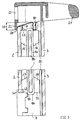
- FIGS. 4 to 7 each show essential components of a Door in different views.
- On the outer pane 3 are again, analogous to the embodiment according to FIG. 1 to 3, two columnar, designed as profile parts and carrier elements running essentially parallel to one another 5 and 6 attached.
- the two support elements 5 and 6 differ from the embodiment according to FIG 1 to 3 only on the outer sides facing away from each other a continuous flange 50 or 60 on their mutually facing insides only on the outer edges a flange 53 and 63, respectively an air exchange and thus a temperature drop in to reach the hollow support elements 5 and 6 and Avoid air turbulence in the door.
- At the flange edges 50 and 53 or 60 and 63 of the carrier elements 5 and 6 embossments 59 and 69 are also provided, which define the distance between the carrier elements 5 and 6 and the outer pane 3 ensure during the gluing process.
- each support element 5 and 6 On the flat surface facing away from the outer pane 3 of the middle part 51, 61 of each support element 5 and 6 in each case a spacer 55 or 65 in a central area arranged.
- Each spacer 55 and 65 is in one corresponding opening (only opening 66 in the carrier element 6 in FIGS. 6 and 7) in the sheet metal of the carrier elements 5 and 6 inserted.
- the dimensions of the spacers 55 and 65 are preferably chosen somewhat larger than the dimensions of the openings (66) in the carrier elements 5 and 6, so that the elastic spacers 55 and 65 under an elastic deformation in the corresponding openings pressed in and by the restoring force now acting be held firmly in the opening. Additional fasteners are therefore not necessary and the spacers 55 and 65 can also from the support elements 5 and 6 can be removed.
- the two spacers 55 and 65 lie with a Opening (66) overlapping edge on the surface of the support elements 5 and 6 so that the opening (66) seals is.
- the spacers have 55 and 65 a rectangular contour and one of the surface of the associated support element 5 and 6 convex surface on the outside.
- the shape of the spacers 55 and 65 is of course not on this Shape limited, but can also be chosen differently become.
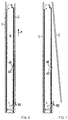
- FIGS. 6 and 7 each show a side view of the door according to FIG 4 and 5 with an installed or removed inner pane 2.
- a receiving element 85 in FIG 6 and 7 for the inner pane 2 attached.
- Each holding element (85) has a receiving groove into which the inner pane 2 can be inserted and is the weight of the inner pane 2 in the vertical Position of the door.
- it is Inner pane 2 essentially parallel to the inner surface the carrier elements (6) aligned and lies with their inside on the elastic spacers 55 and 65 (only 65 shown in FIGS. 6 and 7), preferably again under a bias. This is between the Inner pane 2 and the surface of the carrier element (6) Gap formed.
- the inner pane 2 can now be removed from the receiving element 85 in Removed the direction of the arrow shown, designated P become. With this removal movement slides the inner pane 2 on the surfaces of the spacer 55 and 65 along.
- the spacers 55 and 65 are therefore again at least on its surface from a slippery one Material formed, preferably again with the above Materials and sliding friction coefficients.
- the inner pane 2 from the receiving groove of the receiving element 85 it can be swung forward and be removed, as illustrated in FIG 7.
- the on the side of the inner pane opposite the receiving element 85 predictable additional recording device is in 6 and 7 not shown, but can again as in the embodiments shown in FIGS 1 to 3 be so that the inner pane 2 against a resetting Element in the further receiving device in the direction of shown arrow P is pressed until it comes out of the receiving element 85 can be removed and then in the shown in FIG7 be removed from the door can.
- the inner pane 2 can also be embodied snapped onto the support elements 5 and 6, clipped on or be releasably attached in another way. You can do this in particular on the inner pane 2 on its carrier elements 5 and 6 facing surface one or more locking elements, for example double leg springs or the like, are attached, in particular by an adhesive connection, and corresponding to the support elements 5 and 6 Openings can be provided into which the latching elements can be snapped are.
- the movement of the inner pane 2 during assembly or disassembly then has a movement component perpendicular to the support elements 5 and 6 and can additionally a rotary movement around one of the locking elements Execute distant point (or axis).
- Support elements also a surrounding frame, be provided.
- the invention is not based on the exemplary embodiments described limited.
- the exemplary embodiments have in common that according to the invention the at least two support elements (Door pillars) of the oven door formed from a plastic become.
- the plastic is a polymer material that up to a temperature occurring in a muffle door is stable and the necessary for the carrying function in the door Has dimensional stability.
- the plastic has in particular, sufficient mechanical toughness (mechanical Impact resistance) so that it can withstand impact loads like when you open the door not to warp or even breakage of the material.
- the choice of materials according to the invention allows the direct molding or molding of functional parts of the door on the support elements.
- the known sheet metal parts can be Plastic molded parts also have greater design freedom, Achieve color choice and more flexible design.
Landscapes
- Engineering & Computer Science (AREA)
- Chemical & Material Sciences (AREA)
- Combustion & Propulsion (AREA)
- Mechanical Engineering (AREA)
- General Engineering & Computer Science (AREA)
- Securing Of Glass Panes Or The Like (AREA)
- Seal Device For Vehicle (AREA)
Applications Claiming Priority (2)
| Application Number | Priority Date | Filing Date | Title |
|---|---|---|---|
| DE19957515 | 1999-11-30 | ||
| DE19957515 | 1999-11-30 |
Publications (3)
| Publication Number | Publication Date |
|---|---|
| EP1106932A2 true EP1106932A2 (fr) | 2001-06-13 |
| EP1106932A3 EP1106932A3 (fr) | 2002-01-30 |
| EP1106932B1 EP1106932B1 (fr) | 2004-04-28 |
Family
ID=7930800
Family Applications (1)
| Application Number | Title | Priority Date | Filing Date |
|---|---|---|---|
| EP00117908A Expired - Lifetime EP1106932B1 (fr) | 1999-11-30 | 2000-08-18 | Porte de four avec éléments de support en matière plastique |
Country Status (2)
| Country | Link |
|---|---|
| EP (1) | EP1106932B1 (fr) |
| DE (1) | DE50006235D1 (fr) |
Cited By (13)
| Publication number | Priority date | Publication date | Assignee | Title |
|---|---|---|---|---|
| DE10243552A1 (de) * | 2002-09-19 | 2004-04-01 | BSH Bosch und Siemens Hausgeräte GmbH | Backofentür und Türboden dafür |
| EP1475570A3 (fr) * | 2003-05-07 | 2005-01-26 | Samsung Electronics Co., Ltd. | Porte de four avec fenêtre |
| EP1522250A2 (fr) * | 2003-10-10 | 2005-04-13 | Diehl AKO Stiftung & Co. KG | Elément de boítier d'un appareil ménager |
| EP1548367A2 (fr) | 2003-12-22 | 2005-06-29 | Electrolux Home Products N.V. | Dispositif pour la fermeture de l'orifice d'enceinte d'un appareil ménager |
| WO2006059303A3 (fr) * | 2004-12-01 | 2007-04-26 | Arcelik As | Appareil de cuisson |
| EP1939534A2 (fr) | 2006-12-21 | 2008-07-02 | BSH Bosch und Siemens Hausgeräte GmbH | Porte d'appareil ménager |
| EP2011399A1 (fr) * | 2007-07-02 | 2009-01-07 | Electrolux Home Products Corporation N.V. | Porte de four avec cadre de porte et panneau de porte |
| DE10360385B4 (de) * | 2003-12-22 | 2010-06-24 | Electrolux Home Products Corporation N.V. | Türscharnier für eine Tür eines Haushaltsgeräts sowie Haushaltsgerät mit wenigstens einem Türscharnier |
| WO2010076173A1 (fr) * | 2008-12-30 | 2010-07-08 | Arcelik Anonim Sirketi | Four comprenant une porte |
| EP2341292A1 (fr) * | 2009-12-30 | 2011-07-06 | Electrolux Home Products Corporation N.V. | Porte de four avec charnière de porte en plastique et procédé d'assemblage de cette charnière de porte en plastique |
| ES2384921A1 (es) * | 2008-09-30 | 2012-07-16 | Bsh Bosch Und Siemens Hausgerate Gmbh | Puerta de horno para el espacio de cocción de un horno preferiblemente con un dispositivo para la autolimpieza pirolítica. |
| EP2615377A1 (fr) * | 2012-01-13 | 2013-07-17 | Electrolux Home Products Corporation N.V. | Cavité de four et four |
| EP3031328A3 (fr) * | 2014-12-08 | 2016-07-20 | Marion Stadler | Support pour claies pour un four de cuisson presentant une chambre de cuisson destinee a des produits a base de pate |
Citations (2)
| Publication number | Priority date | Publication date | Assignee | Title |
|---|---|---|---|---|
| DE19705120A1 (de) | 1997-02-11 | 1998-08-13 | Gaggenau Hausgeraete Gmbh | Backofentür |
| DE19738504C1 (de) | 1997-09-03 | 1998-11-26 | Aeg Hausgeraete Gmbh | Tür für ein Haushaltsgerät, insbesondere einen Haushaltsgarofen |
Family Cites Families (2)
| Publication number | Priority date | Publication date | Assignee | Title |
|---|---|---|---|---|
| DE59702655D1 (de) * | 1996-06-05 | 2000-12-28 | Aeg Hausgeraete Gmbh | Tür zum Verschliessen der Ofenmuffel eines Back- und Bratofens |
| DE19738505C1 (de) * | 1997-09-03 | 1999-03-18 | Aeg Hausgeraete Gmbh | Tür für ein Haushaltsgerät, insbesondere einen Haushaltsgarofen |
-
2000
- 2000-08-18 EP EP00117908A patent/EP1106932B1/fr not_active Expired - Lifetime
- 2000-08-18 DE DE50006235T patent/DE50006235D1/de not_active Expired - Lifetime
Patent Citations (2)
| Publication number | Priority date | Publication date | Assignee | Title |
|---|---|---|---|---|
| DE19705120A1 (de) | 1997-02-11 | 1998-08-13 | Gaggenau Hausgeraete Gmbh | Backofentür |
| DE19738504C1 (de) | 1997-09-03 | 1998-11-26 | Aeg Hausgeraete Gmbh | Tür für ein Haushaltsgerät, insbesondere einen Haushaltsgarofen |
Cited By (24)
| Publication number | Priority date | Publication date | Assignee | Title |
|---|---|---|---|---|
| DE10243552A1 (de) * | 2002-09-19 | 2004-04-01 | BSH Bosch und Siemens Hausgeräte GmbH | Backofentür und Türboden dafür |
| EP1475570A3 (fr) * | 2003-05-07 | 2005-01-26 | Samsung Electronics Co., Ltd. | Porte de four avec fenêtre |
| EP1522250A2 (fr) * | 2003-10-10 | 2005-04-13 | Diehl AKO Stiftung & Co. KG | Elément de boítier d'un appareil ménager |
| EP1548367B1 (fr) * | 2003-12-22 | 2010-10-13 | Electrolux Home Products Corporation N.V. | Dispositif pour la fermeture de l'orifice d'enceinte d'un appareil ménager |
| EP1548367A2 (fr) | 2003-12-22 | 2005-06-29 | Electrolux Home Products N.V. | Dispositif pour la fermeture de l'orifice d'enceinte d'un appareil ménager |
| DE10362318B4 (de) * | 2003-12-22 | 2011-02-03 | Electrolux Home Products Corporation N.V. | Türscharnier für eine Tür eines Haushaltsgeräts sowie Haushaltsgerät mit wenigstens einem Türscharnier |
| DE10360385B4 (de) * | 2003-12-22 | 2010-06-24 | Electrolux Home Products Corporation N.V. | Türscharnier für eine Tür eines Haushaltsgeräts sowie Haushaltsgerät mit wenigstens einem Türscharnier |
| WO2006059303A3 (fr) * | 2004-12-01 | 2007-04-26 | Arcelik As | Appareil de cuisson |
| EP1939534A2 (fr) | 2006-12-21 | 2008-07-02 | BSH Bosch und Siemens Hausgeräte GmbH | Porte d'appareil ménager |
| EP1939534A3 (fr) * | 2006-12-21 | 2011-01-19 | BSH Bosch und Siemens Hausgeräte GmbH | Porte d'appareil ménager |
| EP2011399A1 (fr) * | 2007-07-02 | 2009-01-07 | Electrolux Home Products Corporation N.V. | Porte de four avec cadre de porte et panneau de porte |
| WO2009003591A1 (fr) * | 2007-07-02 | 2009-01-08 | Electrolux Home Product Corporation N.V. | Porte de four avec un cadre de porte et un panneau de porte |
| EP2263466A3 (fr) * | 2007-07-02 | 2015-08-26 | Electrolux Home Products Corporation N.V. | Porte de four avec cadre de porte et panneau de porte |
| ES2384921A1 (es) * | 2008-09-30 | 2012-07-16 | Bsh Bosch Und Siemens Hausgerate Gmbh | Puerta de horno para el espacio de cocción de un horno preferiblemente con un dispositivo para la autolimpieza pirolítica. |
| WO2010076173A1 (fr) * | 2008-12-30 | 2010-07-08 | Arcelik Anonim Sirketi | Four comprenant une porte |
| AU2010338367B2 (en) * | 2009-12-30 | 2014-05-01 | Electrolux Home Products Corporation N.V. | An oven door with a plastic door column and a method for assembling said plastic door column |
| EP2341292A1 (fr) * | 2009-12-30 | 2011-07-06 | Electrolux Home Products Corporation N.V. | Porte de four avec charnière de porte en plastique et procédé d'assemblage de cette charnière de porte en plastique |
| WO2011080178A1 (fr) * | 2009-12-30 | 2011-07-07 | Electrolux Home Products Corporation N.V. | Porte de four avec colonne de porte en plastique et procédé d'assemblage de ladite colonne de porte en plastique |
| CN102667347A (zh) * | 2009-12-30 | 2012-09-12 | 伊莱克斯家用产品股份有限公司 | 具有塑料门柱的炉门和用于组装所述塑料门柱的方法 |
| EP2615377A1 (fr) * | 2012-01-13 | 2013-07-17 | Electrolux Home Products Corporation N.V. | Cavité de four et four |
| CN104067057A (zh) * | 2012-01-13 | 2014-09-24 | 伊莱克斯家用产品股份有限公司 | 烤箱腔体和烤箱 |
| WO2013104644A1 (fr) * | 2012-01-13 | 2013-07-18 | Electrolux Home Products Corporation N. V. | Cavité de four et four |
| US10371388B2 (en) | 2012-01-13 | 2019-08-06 | Electrolux Home Products Corporation N.V. | Oven cavity and oven |
| EP3031328A3 (fr) * | 2014-12-08 | 2016-07-20 | Marion Stadler | Support pour claies pour un four de cuisson presentant une chambre de cuisson destinee a des produits a base de pate |
Also Published As
| Publication number | Publication date |
|---|---|
| EP1106932A3 (fr) | 2002-01-30 |
| EP1106932B1 (fr) | 2004-04-28 |
| DE50006235D1 (de) | 2004-06-03 |
Similar Documents
| Publication | Publication Date | Title |
|---|---|---|
| EP1106932B1 (fr) | Porte de four avec éléments de support en matière plastique | |
| DE19738506C1 (de) | Tür für ein Haushaltsgerät, insbesondere einen Haushaltsgarofen, mit Zwischenscheibe mit Abstandshalterahmen | |
| EP3333489B2 (fr) | Appareil de cuisson ménager | |
| EP1076210B1 (fr) | Porte pour un dispositif, en particulier pour un four, avec corps élastiques de retour pour supporter les panneaux | |
| WO2022017794A1 (fr) | Porte et appareil ménager de cuisson | |
| EP1081437A2 (fr) | Porte pour un dispositif, en particulier pour un four, avec un support pour plusieurs panneaux | |
| EP1079180A2 (fr) | Porte pour un dispositif, en particulier pour un four, avec panneaux susceptibles d'être montés de manière infaillible | |
| EP1069378B1 (fr) | Porte pou un dispositif, notamment pour un four de cuisson | |
| EP0900987B1 (fr) | Porte pour un appareil ménager, notamment pour un four ménager pour la cuisson à point | |
| EP2634493B1 (fr) | Porte pour un appareil ménager destiné à préparer des produits alimentaires, dotée d'une pièce de support | |
| EP2921782B1 (fr) | Porte d'appareil ménager avec revêtement conçu comme un composant hybride pour au moins une vitre-porte et appareil ménager équipé d'une telle porte | |
| EP1687571A1 (fr) | Appareil domestique comportant une baguette de commande | |
| DE19738505C1 (de) | Tür für ein Haushaltsgerät, insbesondere einen Haushaltsgarofen | |
| EP2430368B1 (fr) | Porte avec un élément support | |
| DE102021204626B4 (de) | Tür für ein Küchengerät und Küchengerät mit einer derartigen Tür | |
| EP1555486A2 (fr) | Porte de four | |
| EP0953807A2 (fr) | Porte à hublot pour appareil ménager | |
| EP2072722B1 (fr) | Dispositif de verrouillage soutenu par une force de fermeture | |
| EP1172614B1 (fr) | Porte pour appareil ménager, en particulier pour four de cuisson | |
| EP1548367B1 (fr) | Dispositif pour la fermeture de l'orifice d'enceinte d'un appareil ménager | |
| DE29724279U1 (de) | Haushaltsgarofen mit Tür mit herausnehmbarer Zwischenscheibe | |
| DE102020209247A1 (de) | Tür und Haushaltsgargerät | |
| DE29724273U1 (de) | Tür für ein Haushaltsgerät, insbesondere einen Haushaltsgarofen, mit Zwischenscheibe | |
| EP4185815B1 (fr) | Porte et dispositif de cuisson domestique | |
| DE102010029331B4 (de) | Gargerätetür |
Legal Events
| Date | Code | Title | Description |
|---|---|---|---|
| PUAI | Public reference made under article 153(3) epc to a published international application that has entered the european phase |
Free format text: ORIGINAL CODE: 0009012 |
|
| AK | Designated contracting states |
Kind code of ref document: A2 Designated state(s): CH DE FR GB IT LI Kind code of ref document: A2 Designated state(s): AT BE CH CY DE DK ES FI FR GB GR IE IT LI LU MC NL PT SE |
|
| AX | Request for extension of the european patent |
Free format text: AL;LT;LV;MK;RO;SI |
|
| PUAL | Search report despatched |
Free format text: ORIGINAL CODE: 0009013 |
|
| AK | Designated contracting states |
Kind code of ref document: A3 Designated state(s): AT BE CH CY DE DK ES FI FR GB GR IE IT LI LU MC NL PT SE |
|
| AX | Request for extension of the european patent |
Free format text: AL;LT;LV;MK;RO;SI |
|
| 17P | Request for examination filed |
Effective date: 20020218 |
|
| AKX | Designation fees paid |
Free format text: CH DE FR GB IT LI |
|
| 17Q | First examination report despatched |
Effective date: 20030624 |
|
| GRAP | Despatch of communication of intention to grant a patent |
Free format text: ORIGINAL CODE: EPIDOSNIGR1 |
|
| GRAS | Grant fee paid |
Free format text: ORIGINAL CODE: EPIDOSNIGR3 |
|
| GRAA | (expected) grant |
Free format text: ORIGINAL CODE: 0009210 |
|
| AK | Designated contracting states |
Kind code of ref document: B1 Designated state(s): CH DE FR GB IT LI |
|
| REG | Reference to a national code |
Ref country code: GB Ref legal event code: FG4D Free format text: NOT ENGLISH |
|
| REG | Reference to a national code |
Ref country code: CH Ref legal event code: EP |
|
| REG | Reference to a national code |
Ref country code: CH Ref legal event code: NV Representative=s name: TROESCH SCHEIDEGGER WERNER AG |
|
| REG | Reference to a national code |
Ref country code: IE Ref legal event code: FG4D Free format text: GERMAN |
|
| REF | Corresponds to: |
Ref document number: 50006235 Country of ref document: DE Date of ref document: 20040603 Kind code of ref document: P |
|
| GBT | Gb: translation of ep patent filed (gb section 77(6)(a)/1977) |
Effective date: 20040713 |
|
| REG | Reference to a national code |
Ref country code: IE Ref legal event code: FD4D |
|
| ET | Fr: translation filed | ||
| PLBE | No opposition filed within time limit |
Free format text: ORIGINAL CODE: 0009261 |
|
| STAA | Information on the status of an ep patent application or granted ep patent |
Free format text: STATUS: NO OPPOSITION FILED WITHIN TIME LIMIT |
|
| 26N | No opposition filed |
Effective date: 20050131 |
|
| PGFP | Annual fee paid to national office [announced via postgrant information from national office to epo] |
Ref country code: CH Payment date: 20070828 Year of fee payment: 8 |
|
| PGFP | Annual fee paid to national office [announced via postgrant information from national office to epo] |
Ref country code: GB Payment date: 20070829 Year of fee payment: 8 |
|
| REG | Reference to a national code |
Ref country code: CH Ref legal event code: PL |
|
| GBPC | Gb: european patent ceased through non-payment of renewal fee |
Effective date: 20080818 |
|
| PG25 | Lapsed in a contracting state [announced via postgrant information from national office to epo] |
Ref country code: CH Free format text: LAPSE BECAUSE OF NON-PAYMENT OF DUE FEES Effective date: 20080831 Ref country code: LI Free format text: LAPSE BECAUSE OF NON-PAYMENT OF DUE FEES Effective date: 20080831 |
|
| PG25 | Lapsed in a contracting state [announced via postgrant information from national office to epo] |
Ref country code: GB Free format text: LAPSE BECAUSE OF NON-PAYMENT OF DUE FEES Effective date: 20080818 |
|
| PGFP | Annual fee paid to national office [announced via postgrant information from national office to epo] |
Ref country code: DE Payment date: 20140821 Year of fee payment: 15 |
|
| PGFP | Annual fee paid to national office [announced via postgrant information from national office to epo] |
Ref country code: IT Payment date: 20140828 Year of fee payment: 15 |
|
| REG | Reference to a national code |
Ref country code: FR Ref legal event code: PLFP Year of fee payment: 16 |
|
| PGFP | Annual fee paid to national office [announced via postgrant information from national office to epo] |
Ref country code: FR Payment date: 20150626 Year of fee payment: 16 |
|
| REG | Reference to a national code |
Ref country code: DE Ref legal event code: R119 Ref document number: 50006235 Country of ref document: DE |
|
| PG25 | Lapsed in a contracting state [announced via postgrant information from national office to epo] |
Ref country code: IT Free format text: LAPSE BECAUSE OF NON-PAYMENT OF DUE FEES Effective date: 20150818 |
|
| PG25 | Lapsed in a contracting state [announced via postgrant information from national office to epo] |
Ref country code: DE Free format text: LAPSE BECAUSE OF NON-PAYMENT OF DUE FEES Effective date: 20160301 |
|
| REG | Reference to a national code |
Ref country code: FR Ref legal event code: ST Effective date: 20170428 |
|
| PG25 | Lapsed in a contracting state [announced via postgrant information from national office to epo] |
Ref country code: FR Free format text: LAPSE BECAUSE OF NON-PAYMENT OF DUE FEES Effective date: 20160831 |