EP1107007B1 - Dispositif de freinage pour roues d'un véhicule avec dispositif de contrôle intégré, et procédé pour contrôler la force de freinage - Google Patents
Dispositif de freinage pour roues d'un véhicule avec dispositif de contrôle intégré, et procédé pour contrôler la force de freinage Download PDFInfo
- Publication number
- EP1107007B1 EP1107007B1 EP00122210A EP00122210A EP1107007B1 EP 1107007 B1 EP1107007 B1 EP 1107007B1 EP 00122210 A EP00122210 A EP 00122210A EP 00122210 A EP00122210 A EP 00122210A EP 1107007 B1 EP1107007 B1 EP 1107007B1
- Authority
- EP
- European Patent Office
- Prior art keywords
- wheel
- brake
- rotational state
- setpoint
- control unit
- Prior art date
- Legal status (The legal status is an assumption and is not a legal conclusion. Google has not performed a legal analysis and makes no representation as to the accuracy of the status listed.)
- Expired - Lifetime
Links
- 238000000034 method Methods 0.000 claims abstract description 23
- 230000005291 magnetic effect Effects 0.000 claims description 12
- 230000008859 change Effects 0.000 claims description 8
- 230000003993 interaction Effects 0.000 claims description 6
- 230000033001 locomotion Effects 0.000 claims description 6
- 230000003287 optical effect Effects 0.000 claims description 3
- 230000008569 process Effects 0.000 claims description 3
- 238000011217 control strategy Methods 0.000 claims description 2
- 230000007257 malfunction Effects 0.000 claims 2
- 238000013022 venting Methods 0.000 claims 1
- 210000000056 organ Anatomy 0.000 abstract description 17
- 230000002093 peripheral effect Effects 0.000 description 15
- 238000001514 detection method Methods 0.000 description 8
- 230000002457 bidirectional effect Effects 0.000 description 5
- 230000001133 acceleration Effects 0.000 description 3
- 230000000712 assembly Effects 0.000 description 3
- 238000000429 assembly Methods 0.000 description 3
- 230000005540 biological transmission Effects 0.000 description 3
- 230000001419 dependent effect Effects 0.000 description 3
- 230000007246 mechanism Effects 0.000 description 3
- 239000000725 suspension Substances 0.000 description 3
- 238000009423 ventilation Methods 0.000 description 3
- 230000005355 Hall effect Effects 0.000 description 2
- 239000011248 coating agent Substances 0.000 description 2
- 238000000576 coating method Methods 0.000 description 2
- 238000010276 construction Methods 0.000 description 2
- 230000008878 coupling Effects 0.000 description 2
- 238000010168 coupling process Methods 0.000 description 2
- 238000005859 coupling reaction Methods 0.000 description 2
- 238000010586 diagram Methods 0.000 description 2
- 230000005294 ferromagnetic effect Effects 0.000 description 2
- 230000010354 integration Effects 0.000 description 2
- 239000000463 material Substances 0.000 description 2
- 230000004044 response Effects 0.000 description 2
- 230000002123 temporal effect Effects 0.000 description 2
- 238000004804 winding Methods 0.000 description 2
- 230000008901 benefit Effects 0.000 description 1
- 230000033228 biological regulation Effects 0.000 description 1
- 238000004364 calculation method Methods 0.000 description 1
- 230000006835 compression Effects 0.000 description 1
- 238000007906 compression Methods 0.000 description 1
- 230000007797 corrosion Effects 0.000 description 1
- 238000005260 corrosion Methods 0.000 description 1
- 230000007423 decrease Effects 0.000 description 1
- 230000000694 effects Effects 0.000 description 1
- 238000005516 engineering process Methods 0.000 description 1
- 239000003302 ferromagnetic material Substances 0.000 description 1
- 238000010438 heat treatment Methods 0.000 description 1
- 230000006872 improvement Effects 0.000 description 1
- 238000009413 insulation Methods 0.000 description 1
- 238000004519 manufacturing process Methods 0.000 description 1
- 238000001208 nuclear magnetic resonance pulse sequence Methods 0.000 description 1
- 230000035699 permeability Effects 0.000 description 1
- 230000009467 reduction Effects 0.000 description 1
- 238000007789 sealing Methods 0.000 description 1
- 210000000697 sensory organ Anatomy 0.000 description 1
- 230000035939 shock Effects 0.000 description 1
- 230000000087 stabilizing effect Effects 0.000 description 1
Images



Classifications
-
- G—PHYSICS
- G01—MEASURING; TESTING
- G01P—MEASURING LINEAR OR ANGULAR SPEED, ACCELERATION, DECELERATION, OR SHOCK; INDICATING PRESENCE, ABSENCE, OR DIRECTION, OF MOVEMENT
- G01P3/00—Measuring linear or angular speed; Measuring differences of linear or angular speeds
- G01P3/42—Devices characterised by the use of electric or magnetic means
- G01P3/44—Devices characterised by the use of electric or magnetic means for measuring angular speed
- G01P3/48—Devices characterised by the use of electric or magnetic means for measuring angular speed by measuring frequency of generated current or voltage
- G01P3/481—Devices characterised by the use of electric or magnetic means for measuring angular speed by measuring frequency of generated current or voltage of pulse signals
- G01P3/488—Devices characterised by the use of electric or magnetic means for measuring angular speed by measuring frequency of generated current or voltage of pulse signals delivered by variable reluctance detectors
-
- B—PERFORMING OPERATIONS; TRANSPORTING
- B60—VEHICLES IN GENERAL
- B60T—VEHICLE BRAKE CONTROL SYSTEMS OR PARTS THEREOF; BRAKE CONTROL SYSTEMS OR PARTS THEREOF, IN GENERAL; ARRANGEMENT OF BRAKING ELEMENTS ON VEHICLES IN GENERAL; PORTABLE DEVICES FOR PREVENTING UNWANTED MOVEMENT OF VEHICLES; VEHICLE MODIFICATIONS TO FACILITATE COOLING OF BRAKES
- B60T8/00—Arrangements for adjusting wheel-braking force to meet varying vehicular or ground-surface conditions, e.g. limiting or varying distribution of braking force
- B60T8/17—Using electrical or electronic regulation means to control braking
- B60T8/171—Detecting parameters used in the regulation; Measuring values used in the regulation
-
- B—PERFORMING OPERATIONS; TRANSPORTING
- B60—VEHICLES IN GENERAL
- B60T—VEHICLE BRAKE CONTROL SYSTEMS OR PARTS THEREOF; BRAKE CONTROL SYSTEMS OR PARTS THEREOF, IN GENERAL; ARRANGEMENT OF BRAKING ELEMENTS ON VEHICLES IN GENERAL; PORTABLE DEVICES FOR PREVENTING UNWANTED MOVEMENT OF VEHICLES; VEHICLE MODIFICATIONS TO FACILITATE COOLING OF BRAKES
- B60T8/00—Arrangements for adjusting wheel-braking force to meet varying vehicular or ground-surface conditions, e.g. limiting or varying distribution of braking force
- B60T8/32—Arrangements for adjusting wheel-braking force to meet varying vehicular or ground-surface conditions, e.g. limiting or varying distribution of braking force responsive to a speed condition, e.g. acceleration or deceleration
- B60T8/321—Arrangements for adjusting wheel-braking force to meet varying vehicular or ground-surface conditions, e.g. limiting or varying distribution of braking force responsive to a speed condition, e.g. acceleration or deceleration deceleration
- B60T8/329—Systems characterised by their speed sensor arrangements
-
- F—MECHANICAL ENGINEERING; LIGHTING; HEATING; WEAPONS; BLASTING
- F16—ENGINEERING ELEMENTS AND UNITS; GENERAL MEASURES FOR PRODUCING AND MAINTAINING EFFECTIVE FUNCTIONING OF MACHINES OR INSTALLATIONS; THERMAL INSULATION IN GENERAL
- F16D—COUPLINGS FOR TRANSMITTING ROTATION; CLUTCHES; BRAKES
- F16D55/00—Brakes with substantially-radial braking surfaces pressed together in axial direction, e.g. disc brakes
- F16D55/02—Brakes with substantially-radial braking surfaces pressed together in axial direction, e.g. disc brakes with axially-movable discs or pads pressed against axially-located rotating members
- F16D55/22—Brakes with substantially-radial braking surfaces pressed together in axial direction, e.g. disc brakes with axially-movable discs or pads pressed against axially-located rotating members by clamping an axially-located rotating disc between movable braking members, e.g. movable brake discs or brake pads
-
- F—MECHANICAL ENGINEERING; LIGHTING; HEATING; WEAPONS; BLASTING
- F16—ENGINEERING ELEMENTS AND UNITS; GENERAL MEASURES FOR PRODUCING AND MAINTAINING EFFECTIVE FUNCTIONING OF MACHINES OR INSTALLATIONS; THERMAL INSULATION IN GENERAL
- F16D—COUPLINGS FOR TRANSMITTING ROTATION; CLUTCHES; BRAKES
- F16D66/00—Arrangements for monitoring working conditions, e.g. wear, temperature
-
- G—PHYSICS
- G01—MEASURING; TESTING
- G01P—MEASURING LINEAR OR ANGULAR SPEED, ACCELERATION, DECELERATION, OR SHOCK; INDICATING PRESENCE, ABSENCE, OR DIRECTION, OF MOVEMENT
- G01P1/00—Details of instruments
-
- G—PHYSICS
- G01—MEASURING; TESTING
- G01P—MEASURING LINEAR OR ANGULAR SPEED, ACCELERATION, DECELERATION, OR SHOCK; INDICATING PRESENCE, ABSENCE, OR DIRECTION, OF MOVEMENT
- G01P3/00—Measuring linear or angular speed; Measuring differences of linear or angular speeds
- G01P3/42—Devices characterised by the use of electric or magnetic means
- G01P3/44—Devices characterised by the use of electric or magnetic means for measuring angular speed
- G01P3/48—Devices characterised by the use of electric or magnetic means for measuring angular speed by measuring frequency of generated current or voltage
- G01P3/481—Devices characterised by the use of electric or magnetic means for measuring angular speed by measuring frequency of generated current or voltage of pulse signals
-
- F—MECHANICAL ENGINEERING; LIGHTING; HEATING; WEAPONS; BLASTING
- F16—ENGINEERING ELEMENTS AND UNITS; GENERAL MEASURES FOR PRODUCING AND MAINTAINING EFFECTIVE FUNCTIONING OF MACHINES OR INSTALLATIONS; THERMAL INSULATION IN GENERAL
- F16D—COUPLINGS FOR TRANSMITTING ROTATION; CLUTCHES; BRAKES
- F16D66/00—Arrangements for monitoring working conditions, e.g. wear, temperature
- F16D2066/003—Position, angle or speed
Definitions
- the invention relates to a wheel brake assembly and a method for Control of Radbremsmomentes in a motor vehicle.
- Devices of the type mentioned are used in large width application Anti-lock braking systems and thereon based control arrangements for Improvement of directional stability and course stability of motor vehicles in situations with high wheel slip, for example, in the context of a braking operation or at Cornering.
- From DE 44 02 959 C2 is a device for generating a frequency of the wheel speed dependent pulse train known in the field of a wheel bearing provided pole ring and a sensor arranged adjacent thereto. On the basis of the temporal position of the pulses generated by the sensor can via a central ABS control device, the current rotational state of the vehicle wheel determined and the brake pressure to be controlled accordingly.
- the invention is based on the object, one in terms of their reliability to allow improved adjustment of the wheel braking torque.
- the sensor member By arranging the sensor member on the brake caliper assembly, it becomes advantageous manner possible, to the hitherto required, with regard to mechanical Damage sensitive pole ring to renounce and the current state of rotation of the wheel, for example, on the outer circumference of the brake disc with high resolution to detect directly over the brake disc itself.
- the directly with the Brake disc cooperating sensor can be in the brake caliper assembly be integrated, which on the one hand, an effective protection of the sensor itself as well as a protection of the wiring of the sensor is given.
- the sensor element directly to a brake lining element to install.
- the sensor element can in this case similar to a contact for determining the Pad wear used in the friction lining or on a Reibbelagivaplatte be arranged or mounted next to the attached friction lining. This will it is possible to easily change the sensor member with the brake pad, so that with a renewal of the brake pad and a renewal of the sensor organ is reached.
- About the sensor organ can possibly also at the same time the lining thickness or the undershooting of a lining minimum thickness and / or the temperature of Brake disk to be detected.
- a particularly high resolution in the detection of the rotational state of the corresponding wheel is according to a particularly preferred embodiment of Invention achieved in that the sensor element is arranged such that this with the outer peripheral region of the brake disc interacts.
- the Arrange sensor body such that this with the radially extending webs in Interaction occurs.
- the brake disc in the outer peripheral region with To provide protrusions or teeth, so that the sensor organ with these teeth in Interaction occurs. This will result in even higher resolution during acquisition achieved the current rotational state.
- a particularly striking pulse sequence can be advantageous in terms of manufacturing technology Be achieved by the brake disc with several, on a pitch circle lying holes is provided, wherein the sensor element is arranged such that this interacts with the brake disc in the region of the pitch circle. Instead of These holes can also be formed in the friction surface radially extending grooves be provided.
- the interaction between the sensor organ and the brake disc is based in advantageously on magnetic effects. This will be a high Pollution insensitivity reached. Alternatively or in combination With this measure, it is also possible effects of electrical, in particular field electrical, optical or acoustic nature for the immediate detection of Rotation of the brake disc by the brake disc body itself use.
- the brake disc is preferably made a ferromagnetic material formed or at least in the region of Sensor organ appropriately doped or with a ferromagnetic coating Mistake.
- the sensor element is arranged such that this one Inductance change detected by a system comprising the brake disc.
- the sensor element on a coil, in which as a result of alternating intensity of a magnetic field voltage pulses are induced.
- the coil is arranged for this purpose advantageously around a bobbin, wherein the bobbin is brought so to the brake disc, that from the Spool core emerging field lines temporarily enter the brake disc.
- the sensor element instead of The described coil, it is also possible, the sensor element as a Hall effect sensor train.
- the required magnetic field can via a permanent magnet or be generated via a coil.
- the intensity of the Hall effect sensor passing through magnetic field is as in the other embodiments by the geometry of the sensor organ currently adjacent portion of the Brake disc (bar, bore, groove) determined.
- the detected field strength changes upon rotation of the brake disc according to the geometry of the sensor organ approaching section of the brake disc.
- a central control device is provided for this purpose a specific wheel specific target instantaneous rotational state, in particular a target wheel speed, target wheel tension and / or setpoint frequency. Based on this few easily standardizable presetting data can be given by the wheel side Control device, the braking torque to be set automatically.
- the target instantaneous rotational state can be via a bus system or via a simple impulse line the provided in the wheel area decentralized control unit are supplied.
- control unit integrated in a brake caliper assembly.
- a corresponding housing section can directly into a wheel brake cylinder housing or integrated into a portion of a brake caliper.
- the detection of the rotation of the brake disc can in this case directly over a example in the range of one of the brake disc facing end face of the corresponding brake piston arranged sensor element respectively.
- a reduction or an increase of the wheel braking torque can in this case directly caused in the brake caliper control unit are caused when the detected pulse rate of a predetermined setpoint, in particular a deviates predetermined pulse rate.
- the arrangement according to the invention is particularly suitable for brake systems with electromechanical brake shoe operation without, however, limited to be. You can in a particularly advantageous manner with brake systems with Hydraulic brake shoe application apply.
- the rotational state of a wheel is in the present case, at least by the Angular velocity and / or its derivative i. the angular acceleration certainly.
- the control arrangement advantageously has a central one Control device based on a vehicle target course and on the basis of current wheel braking torques for each decentralized control unit a setpoint determined.
- This setpoint may be according to another particularly preferred Embodiment of the invention also taking into account the current Radaufstands kit be determined. The latter can do this via the degree of compression or roll, yaw and pitch accelerations are determined.
- the target rotational state determined by the central control device is determined according to a preferred method sequence depending on the current Moving state of the vehicle body determined.
- the determination of the target rotational state based on a Vehicle course stabilizing control algorithm in particular ASR, EDS, as well as ESP control strategies.
- the target wheel speed for example, to a Radmitten set speed to be matched, resulting from the Driving speed +/- 1 ⁇ 2 gauge * yaw rate can be determined.
- a target / actual comparison and the Wheel braking torque decreases when the actual angular velocity of the wheel is smaller as the target angular velocity.
- the wheel braking torque increases when the actual angular velocity is greater than the target angular velocity.
- the signals representative of the actual angular velocity of each wheel are advantageously supplied to the common control device, so that the common control device also this individual for each wheel Can process information.
- the by the Rad facilityen control units individually adjusted braking forces of the central Control device supplied.
- the transmission in terms of the actual and / or the desired rotational state representative signals between the preferably integrated in the braking device decentralized control units and the central control device takes place preferably via a bus system.
- the signals representative of the actual rotational state are preferably generated by a sensor device which is directly connected to a brake disk in Interaction stands.
- the processing of the respective target and actual rotational state is preferably carried out within an integrated into the wheel brake device Housing section, in which the control unit is received. Further advantageous measures are the subject of the dependent claims.
- the wheel brake device shown in Fig. 1 comprises a brake disc 1 and a Brake caliper assembly 2.
- the brake disc 1 is here as internally ventilated brake disc formed and has this purpose ventilation ducts 3 on each of the webs. 4 are separated from each other.
- the webs 4 are integrally formed with the brake disc 1 and extend in the radial direction to the radial level of the friction surface. 5 bounding outer peripheral edges 6 and 7.
- the friction surface 5 is of a front gripping portion 9 of the brake caliper assembly. 2 overlapped. Between the front gripping area 9 and the friction surface 5 is a here only suggestively recognizable brake pad member 10, provided the interchangeable housed in the brake caliper assembly 2.
- the actuating mechanism comprises an electromechanical drive device comprising an electric motor, a Transmission device and a spindle mechanism comprises.
- the braking force via a fluid-actuated brake piston, in a Housing portion of the brake caliper assembly is housed to produce.
- the Actuating force is controlled by a wheel electronics 11, which also here in a, in the brake caliper assembly 2 integrated housing portion 12 in sealed Way is used.
- the housing portion 12 is arranged and formed so that this also in If the maximum load of the brake is not subject to excessive heating.
- a sensor member 14 is integrated directly into Collaboration with the brake disc 1 generates signals from which the Current rotational state of the corresponding wheel can be determined.
- the sensor member 14 is arranged in this embodiment such that this Webs 4 of the brake disc 1 detected.
- the sensor element 14 in the Brake caliper assembly 2 aligned on the outer peripheral surface, attached.
- the Attachment of the sensor element 14 takes place via a holding body 16 which is in the Brake caliper assembly 2 used, in particular is pressed.
- the sensor member 14 is integrated via an integrated into the brake caliper assembly 2, in particular cast-in connecting line 15 with said wheel electronics 11 connected.
- the connecting line 15 is provided with a heat-resistant insulation and led out in a sealing manner from the sensor-holding body 16.
- the connecting line 15 extends completely shielded within a channel means in the brake caliper assembly 2 is trained.
- the sensor element 14 comprises a coil, which in Dependence of a changed by the changing presence of the webs 4 Field strength generates pulse-like signals. These signals are called above Connecting line 15 of the wheel electronics 11 supplied and evaluated there. alternative For this purpose, the signals obtained can also be supplied to a central control device become.
- the wheel electronics 11 is designed such that these directly a change in the Braking force causes when the determined via the sensor member 14 rotational state of the Rades deviates from a predetermined target rotational state.
- This target rotational state is For example, chosen such that the wheel peripheral speed substantially the Relative speed of the vehicle relative to the roadway in the area of respective Radêtress scholars possibly also taking into account a calculated target slip (ESP), corresponds.
- ESP calculated target slip
- the rotational state of the brake disc 1 is particularly in this Brake disc assembly also possible, one on a field electric, optical or acoustic interaction based detection of the rotation of the brake disc make.
- FIG. 2 another embodiment of a wheel brake is shown, which is from the embodiment described above with reference to FIG in particular by the design of the brake disc 1 and the arrangement of Sensor organ 2 different.
- the brake disk 1 provided here is in the outer peripheral region with a plurality provided by projections, here by evenly spaced, integral with the Brake disk formed teeth 17 are formed.
- the division of the teeth is here chosen so that they are related to the thickness t of the brake disc 1 in the range of t / 3 to t lies, with the larger ratio with thin brake disks 1 and the smaller one Ratio in thicker brake discs 1 is used.
- the teeth 17 are with Advantage designed such that their measured in the circumferential direction tooth width b is greater than the distance also measured in the circumferential direction adjacent Tooth flanks.
- the relative movement of the teeth relative to the brake caliper assembly 2 is also detected by a sensor member 14.
- the sensor member 14 is different from the Embodiment acc. Fig. 1 in a leading to the front gripping area 9 leading Arm portion 18 is arranged.
- the sensor member 14 is also completely over the brake caliper assembly included connecting line 15 coupled to a wheel electronics 11.
- connection cable 15 in the outdoor area, but preferably in a corresponding running open groove.
- Fig. 3 is a sketch of a suspension for a vehicle wheel shown here Shock 19 and lower arm 20 has.
- the brake disc provided here 1 also has ventilation channels 3, which are separated by webs 4 from each other.
- the brake caliper assembly 2 provided here has a recess 21, in which interacts directly with the brake disc 1 sensor member 14th recorded, in particular is locked.
- a sensor member 14 is shown, in which the presence of a web 4 of the brake disc 1 is detected via a change of a magnetic field.
- the history the field lines 21 is shown here in a hint.
- the magnetic field can over a trained either as a permanent magnet magnetic body 22 or another Coil, which is possibly operated pulsed, are generated.
- Arrives at the illustrated Embodiment a web 4 of the brake disc 1 in the exit region of the field lines of the sensor element 14, a voltage pulse is generated in a sensor winding 23 induced. This can by appropriate control of a control device recorded and further processed.
- the signal intensity can be further increased by, for example, in Fig. 3c also indicated by the construction of the brake caliper or brake fist itself Entry of the field lines in the brake disc 1 is further supported.
- Figure 3d is sketchy another embodiment of the sensor organ 14th represented, which is also the presence of a geometry feature of the brake disc. 1 detected by a change of a magnetic field.
- the sensor element is here However, formed such that the field lines 21 only a short distance in the Return brake disc 1.
- both for Steger charged as well as for the detection of integral teeth run the Field lines 21 substantially parallel to the axis of rotation of the brake disc. 1
- Fig. 4a is another embodiment of an inventive Wheel brake simplified.
- the brake disk 1 provided here has a plurality of through holes 24, which at the same distance to Rotation axis X of the brake disc 1 and the same pitch on a pitch circle are arranged.
- the detection of the rotation of the brake disc 1 via the directly cooperating with the brake disc 1 sensor member 14, which is located on Height of the pitch circle of the holes 24 is located.
- the sensor element 14 is such designed that this during the passage of a bore 24 or when changing from Hole 24 and brake disc material generates a pulse-like signal.
- the sensor element 14 here directly adjoins one Base plate 25 of a brake pad attached and also serves as Coating thickness sensor.
- the sensor member 14 is for this purpose with a coupling portion 26th provided, which gradually together with a wear layer 27 of the brake pad is removed.
- the sensor element 14 is here via a flexible and heat-resistant connection line 15 connected to a control system.
- the sensor arrangement shown here can also in connection with brake discs find application in which instead of or in Combination with the through holes 24 radially extending grooves in the corresponding friction surface 5 are formed.
- Fig. 5 is greatly simplified another embodiment of a directly with the Brake disc 1 interacting sensor member 14 shown.
- the Brake disk 1 is here similar to that described in connection with FIG. 2 Embodiment along its outer periphery with teeth 17 provided.
- the Sensor member 14 is brought to the outer periphery of the brake disc 1 and such formed to interact with at least two teeth 17. The hereby entering via a tooth 17 in the brake disc 1 field lines via the adjacent or a predetermined spaced further tooth 17 back to Sensor organ 14.
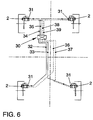
- FIG. 6 schematically shows a control arrangement for controlling the Radbremsmomente shown here a central control device 30 and decentralized wheel-side (end) control units 31 (wheel electronics) has.
- the control units are here with a not shown Power circuit in connection, via which the power supply to the Drive unit of the electromechanical brake is controlled. Based on the Motor current can determine the braking force and the current braking torque getting closed. The maximum value of the motor current can be on the part of the wheel electronics be limited.
- the remote control units 31 including power circuit are here according to the explained in connection with Fig. 1 wheel electronics 11 in one provided directly on the respective brake caliper assembly 2 Housed housing section.
- Each control unit 31 controls the wheel braking torque in response to the detected instantaneous state of rotation of the wheel taking into account a desired value.
- This setpoint is individualized by the central controller 30 for each wheel established. For this purpose, in particular the state of motion of the vehicle body related to the spatial axes, the steering angle as well as the driver given acceleration or deceleration.
- the way for every bike individually determined setpoints are preferably via a bidirectional bus system or as indicated here via signal lines 32, 33, 34, 35 of the respective decentralized Control unit 31 supplied.
- the central Control device 30 can, based on these Radbremsmomente the maximum determine transferable Rad enclosures after or Radspannmomente and this Take the results into account in the further calculation of the setpoints.
- an individual ABS control takes place here, by the wheel electronics from the determined wheel speed and the Radsollformatiere calculates the wheel slip. It is possible in the central Control means 30 to receive an ESP control device, via which the Radsollformatbaum or a target wheel slip for each wheel is calculated individually and via the bus system or a corresponding data line of the respective wheel electronics for further braking force control is supplied.
- a particularly high functional reliability can be achieved in an advantageous manner be achieved in that the bus system at least twice redundant is trained.
- Fig.7 is a preferred embodiment of one for carrying out the Control system according to the invention provided braking force control method shown.
- This includes here the common already described Control device 30 and the individual for each wheel brake assembly provided control units 31.
- the coupling of the control device 30 and the Control units 31 are here via a bidirectional bus system 40, the here is designed to be redundant multiple times.
- the control device 30 is on a shielded against external influences body preferably mounted in the area of the bulkhead of the vehicle.
- the Control device 30 processes information about the instantaneous movement the vehicle body, in particular the yaw rate and their temporal Dissipation.
- the steering wheel angle, the Radaufstands mechanism and their time derivative are taken into account.
- the input information is for example under ASR, EDS and / or ESP control criteria processed. Based on this input information can be used for each Wheel suspension with respect to a target rotational state indicative data are generated. This data, for example, the target angular velocity are via the bus system 40 of the respective wheel brake assembly associated control unit 31st read.
- the respectively required to achieve the predetermined target rotational states setting the braking torque is, for example, on the contact pressure of the brake shoes by the wheel-side control units 31 in the context of a closed control cycle set.
- the directly in the wheel brake assembly Detected information on the rotational state, for example, measuring pulses due geometric characteristics of the respective brake disc by the wheel side Control unit processed.
- the information about the wheel rotation state can be read via the Bus system 40 and the central control device 30 are supplied, so that based on this the vehicle speed and the local Determine wheel traction and, if necessary, further refine the desired wheel rotational states can determine.
- the information on the respective Radsoll-rotation state can also have a Interface device, for example, to a brake system of a vehicle trailer be passed on. This makes it possible, even for the wheels or axles of the Vehicle trailer an improved, preferably individual braking force control make.
- electromechanical Radbremsan in electromechanical Radbremsanssenen a respect to the instantaneous braking force indicative signal feedback to the wheel-side control unit 31 and / or to the central control device 30.
- Such signals can about the power consumption of the respective actuator, in particular the motor current, be generated. It is also possible, measuring members for measuring the actuation force of Provide brake.
Landscapes
- Engineering & Computer Science (AREA)
- Mechanical Engineering (AREA)
- General Engineering & Computer Science (AREA)
- Physics & Mathematics (AREA)
- General Physics & Mathematics (AREA)
- Transportation (AREA)
- Regulating Braking Force (AREA)
- Braking Arrangements (AREA)
- Automobile Manufacture Line, Endless Track Vehicle, Trailer (AREA)
Claims (29)
- Arrangement de frein de roue pour un véhicule comprenant :caractérisé en ce que l'arrangement de contrôle présente une unité de contrôle (31) côté roue intégrée dans l'arrangement de pince de frein (2), laquelle ordonne un réglage du moment de frein de roue correspondant en fonction de l'état de rotation réel détecté de la roue et d'un état de rotation de consigne prédéfini.un arrangement de pince de frein (2) pour produire un moment de frein de roue,un organe de détection (14) pour détecter l'état de rotation momentané d'une roue de véhicule qui entre en interaction avec une section du disque de frein (1),un arrangement de contrôle pour contrôler l'arrangement de pince de frein (2) qui contrôle le moment de frein de roue à l'aide de l'état de rotation réel ou momentané détecté,
- Arrangement de frein de roue selon la revendication 1, caractérisé en ce que l'arrangement de pince de frein (2) est actionné de manière électromécanique.
- Arrangement de frein de roue selon la revendication 1 ou 2, caractérisé en ce que l'unité de contrôle (31) est connectée avec l'organe de détection (14) par le biais d'une ligne de liaison (15) intégrée dans l'arrangement de pince de frein (2).
- Arrangement de frein de roue selon l'une des revendications 1 à 3, caractérisé en ce que l'organe de détection (14) présente un codeur à impulsions.
- Arrangement de frein de roue selon l'une des revendications 1 à 4, caractérisé en ce que l'arrangement de contrôle présente un dispositif de contrôle central (30) pour prédéfinir un état de rotation de consigne, notamment une vitesse de rotation de consigne de roue ou une force de serrage de consigne de roue pour chaque roue.
- Arrangement de frein de roue selon l'une des revendications 1 à 5, caractérisé en ce que l'état de rotation momentané de consigne est acheminé à l'unité de contrôle décentralisée (31) par le biais d'un système de bus.
- Arrangement de frein de roue selon l'une des revendications 1 à 6, caractérisé en ce que le dispositif de contrôle centrale (30) détermine une valeur de consigne pour chaque unité de contrôle décentralisée (31) au moyen d'une trajectoire de consigne du véhicule et au moyen des moments de frein de roue momentanés.
- Arrangement de frein de roue selon l'une des revendications 1 à 7, caractérisé en ce que l'interaction est de nature magnétique, électrique, optique ou acoustique.
- Arrangement de frein de roue selon l'une des revendications 1 à 6, caractérisé en ce que l'organe de détection (14) détecte la modification de l'inductance d'un système entourant le disque de frein.
- Arrangement de frein de roue selon l'une des revendications 1 à 9, caractérisé en ce que l'organe de détection (14) comprend une bobine (23).
- Arrangement de frein de roue selon la revendication 10, caractérisé en ce que la bobine (23) est disposée autour d'un noyau de bobine et que le noyau de bobine est approché du disque de frein (1) de telle sorte que les lignes de champ (21) sortant du noyau de bobine pénètrent dans le disque de frein (1).
- Arrangement de frein de roue selon l'une des revendications 1 à 11, caractérisé en ce que l'organe de détection (14) est monté sur un élément de garniture de frein (10) remplaçable de l'arrangement de pince de frein.
- Arrangement de frein de roue selon l'une des revendications 1 à 12, caractérisé en ce que l'organe de détection (14) est disposé de telle sorte qu'il entre en interaction avec la zone périphérique extérieure du disque de frein (1).
- Arrangement de frein de roue selon l'une des revendications 1 à 12, caractérisé en ce que le disque de frein (1) présente des canaux de ventilation intérieurs (3) qui sont séparés les uns des autres par des montants (4), l'organe de détection (14) étant disposé de telle sorte qu'il entre en interaction avec les montants (4).
- Arrangement de frein de roue selon l'une des revendications 1 à 12, caractérisé en ce que le disque de frein (1) est muni dans la zone périphérique extérieure d'éléments en saillie ou de dents (17) et que l'organe de détection (14) entre en interaction avec les éléments en saillie ou les dents (17).
- Arrangement de frein de roue selon l'une des revendications 1 à 12, caractérisé en ce que l'organe de détection (14) est disposé de telle sorte qu'il entre en interaction avec une zone de surface latérale du disque de frein (1).
- Arrangement de frein de roue selon l'une des revendications 1 à 12, caractérisé en ce que le disque de frein (1) est muni de plusieurs orifices (24) se trouvant sur un cercle primitif de référence et que l'organe de détection (14) est disposé de telle sorte qu'il entre en interaction avec le disque de frein (1) dans la zone du cercle primitif de référence.
- Procédé de contrôle du moment de frein de roue sur un véhicule automobile avec un arrangement de frein de roue selon l'une des revendications 1 à 17,avec lequel des signaux représentant l'état de rotation réel des roues d'au moins un essieu du véhicule sont générés dans le cadre d'une opération de freinage et le moment de frein de roue est contrôlé en fonction de ces signaux, caractérisé par les étapes :comprenant un organe de détection (14) pour détecter l'état de rotation momentané d'une roue de véhicule,comprenant un dispositif de contrôle central (30) commun etcomprenant à chaque fois une unité de contrôle décentralisée (31) côté roue pour chaque roue de véhicule,détermination d'un état de rotation réel pour chaque roue de l'au moins un essieu du véhicule à chaque fois par un organe de détection (14) qui entre en interaction avec une section du disque de frein (1),transmission des signaux représentant l'état de rotation réel pour chaque roue au dispositif de contrôle commun (30),détermination d'un état de rotation de consigne pour chaque roue de l'au moins un essieu du véhicule par le biais du dispositif de contrôle commun (30),transmission des signaux représentant l'état de rotation de consigne à une unité de contrôle décentralisée (31) qui se trouve à chaque fois côté roue, intégrée dans l'arrangement de pince de frein,traitement des signaux représentant l'état de rotation réel et des signaux représentant l'état de rotation de consigne par l'unité de contrôle décentralisée (31) etréglage du moment de frein de roue correspondant en fonction du traitement des signaux d'état de rotation réel et de consigne effectué par l'unité de contrôle décentralisée (31).
- Procédé selon la revendication 18, caractérisé en ce que l'état de rotation de consigne est déterminé en fonction de l'état de déplacement momentané de la structure du véhicule.
- Procédé selon la revendication 18 ou 19, caractérisé en ce que l'état de rotation de consigne est déterminé en fonction des forces de contact momentanées des roues.
- Procédé selon au moins l'une des revendications 18 à 20, caractérisé en ce que l'état de rotation de consigne est déterminé sur la base d'un algorithme de contrôle stabilisant la course du véhicule.
- Procédé selon au moins l'une des revendications 18 à 21, caractérisé en ce qu'une comparaison consigne/réel est effectuée du côté de l'unité de contrôle (31) côté roue et le moment de frein de roue est réduit lorsque la vitesse angulaire réelle de la roue est inférieure à la vitesse angulaire de consigne et que le moment de frein de roue est augmenté lorsque la vitesse angulaire réelle est supérieure à la vitesse angulaire de consigne.
- Procédé selon au moins l'une des revendications 18 à 22, caractérisé en ce qu'au moins les signaux représentatifs de l'état de rotation réel et/ou de consigne sont acheminés au dispositif de contrôle commun (30) par le biais d'un système de bus.
- Procédé selon au moins l'une des revendications 18 à 23, caractérisé en ce que le traitement de l'état de rotation de consigne et réel correspondant s'effectue dans une section de boítier intégrée dans le dispositif de frein de roue dans laquelle est logée l'unité de contrôle (31).
- Procédé selon au moins l'une des revendications 18 à 24, caractérisé en ce qu'un état de rotation de consigne individuel pour chaque roue est déterminé du côté du dispositif de contrôle commun sur la base d'une stratégie ASR, EDS ou ESP puis transmis à l'unité de contrôle (31) côté roue correspondante.
- Procédé selon au moins l'une des revendications 18 à 25, caractérisé en ce qu'un algorithme de contrôle ABS est exécuté du côté de l'unité de contrôle (31) à chaque fois prévue dans la zone de la roue (électronique de roue), notamment en cas de défaut de fonctionnement lors de l'attribution des valeurs de consigne par le dispositif de contrôle central (30).
- Procédé selon au moins l'une des revendications 18 à 26, caractérisé en ce qu'une régulation ABS du moment de freinage est effectué par le dispositif de contrôle commun (30) en cas de défaut de fonctionnement de l'unité de contrôle côté roue.
- Procédé selon au moins l'une des revendications 18 à 27, caractérisé en ce que la vitesse de déplacement du véhicule est calculée à partir des quatre organes de détection (14) côté roue.
- Procédé selon au moins l'une des revendications 18 à 28, caractérisé en ce que dans le cas où aucun signal représentant l'état de rotation de consigne n'est présent du côté du dispositif de contrôle central (30), une régulation ABS est effectuée par l'unité de contrôle (31) côté roue correspondante.
Applications Claiming Priority (2)
| Application Number | Priority Date | Filing Date | Title |
|---|---|---|---|
| DE19957632A DE19957632B4 (de) | 1999-11-30 | 1999-11-30 | Radbremsenanordnung und Verfahren zur Steuerung des Radbremsmomentes |
| DE19957632 | 1999-11-30 |
Publications (3)
| Publication Number | Publication Date |
|---|---|
| EP1107007A2 EP1107007A2 (fr) | 2001-06-13 |
| EP1107007A3 EP1107007A3 (fr) | 2002-07-31 |
| EP1107007B1 true EP1107007B1 (fr) | 2005-11-30 |
Family
ID=7930879
Family Applications (1)
| Application Number | Title | Priority Date | Filing Date |
|---|---|---|---|
| EP00122210A Expired - Lifetime EP1107007B1 (fr) | 1999-11-30 | 2000-10-16 | Dispositif de freinage pour roues d'un véhicule avec dispositif de contrôle intégré, et procédé pour contrôler la force de freinage |
Country Status (3)
| Country | Link |
|---|---|
| EP (1) | EP1107007B1 (fr) |
| AT (1) | ATE311603T1 (fr) |
| DE (2) | DE19957632B4 (fr) |
Cited By (3)
| Publication number | Priority date | Publication date | Assignee | Title |
|---|---|---|---|---|
| DE102012012474A1 (de) * | 2012-06-22 | 2013-12-24 | Knorr-Bremse Systeme für Nutzfahrzeuge GmbH | Scheibenbremsenanordnung mit elektrischer Belagverschleissnachstellvorrichtung und Drehzahlsensor |
| US10060490B2 (en) | 2012-02-10 | 2018-08-28 | Knorr-Bremse Systeme Fuer Nutzfahrzeuge Gmbh | Lining wear adjustment device for a disc brake |
| US10744981B2 (en) | 2018-06-06 | 2020-08-18 | Sensata Technologies, Inc. | Electromechanical braking connector |
Families Citing this family (15)
| Publication number | Priority date | Publication date | Assignee | Title |
|---|---|---|---|---|
| US20050206148A1 (en) * | 2004-03-04 | 2005-09-22 | Bendix Commercial Vehicle Systems Llc | Sensor arrangement for use with an air disc brake |
| US20050275281A1 (en) * | 2004-05-13 | 2005-12-15 | Prescott Robert D | Modular braking system |
| EP1870679A1 (fr) * | 2006-06-20 | 2007-12-26 | Hübner Elektromaschinen GmbH | Dispositif de freinage et/ou de blocage avec codeur magnétique |
| DE102011077034A1 (de) * | 2011-06-07 | 2012-12-13 | Continental Teves Ag & Co. Ohg | Bremsscheibe |
| DE102012009116A1 (de) * | 2012-05-09 | 2013-04-18 | Audi Ag | Vorrichtung zur Drehzahlerfassung für ein Fahrzeug |
| CN103513052B (zh) * | 2013-10-12 | 2016-01-20 | 昆山攀登变频电子科技有限公司 | 一种电动车的一体式测量装置 |
| DE102016221969A1 (de) * | 2016-11-09 | 2018-05-09 | Robert Bosch Gmbh | Trägertopf für eine Bremsscheibe, Bremsscheibeneinrichtung |
| DE102018203700B4 (de) * | 2018-03-12 | 2023-10-12 | Knorr-Bremse Systeme für Schienenfahrzeuge GmbH | Drehwinkelerfassungseinrichtung für eine Komponente einer Bremse eines Fahrzeugs und Verfahren zum Bestimmen einer Drehwinkelposition der Komponente |
| DE102018221573A1 (de) * | 2018-12-12 | 2020-06-18 | Continental Teves Ag & Co. Ohg | Bremsscheibe für eine Fahrzeug-Scheibenbremse |
| DE102020204221A1 (de) | 2020-04-01 | 2021-10-07 | Continental Teves Ag & Co. Ohg | Bremssystem |
| DE102020113509B4 (de) * | 2020-05-19 | 2024-02-01 | Knott Gmbh | Anhängerstabilisierungseinrichtung, Verfahren zur Stabilisierung eines Anhängers, Computerprogramm und Anhänger |
| EP4056958A1 (fr) * | 2021-03-11 | 2022-09-14 | Siemens Aktiengesellschaft | Unité de capteur de vitesse de rotation de frein |
| DE102023122197A1 (de) | 2022-10-11 | 2024-04-11 | Zf Active Safety Gmbh | Dezentrales Steuersystem für eine Kraftfahrzeug-Bremsanlage, Kraftfahrzeug-Bremsanlage und Kraftfahrzeug |
| DE102023205092A1 (de) * | 2023-05-31 | 2024-12-05 | Hl Mando Corporation | Bremsenanordnung mit Vorrichtung zur Erzeugung eines Warnsignals |
| KR20240174912A (ko) * | 2023-06-08 | 2024-12-18 | 현대모비스 주식회사 | 전동식 브레이크 및 이의 제어방법 |
Family Cites Families (12)
| Publication number | Priority date | Publication date | Assignee | Title |
|---|---|---|---|---|
| US3870911A (en) * | 1972-06-21 | 1975-03-11 | Nippon Denso Co | Wheel speed detector for vehicles |
| DE3526189A1 (de) * | 1985-07-23 | 1987-02-05 | Bosch Gmbh Robert | Druckmodulator fuer abs-systeme |
| DE8804238U1 (de) * | 1987-06-05 | 1988-06-09 | TA Triumph-Adler AG, 8500 Nürnberg | Bremsscheibe für Kraftfahrzeuge |
| DE8804239U1 (de) * | 1987-06-05 | 1988-06-01 | TA Triumph-Adler AG, 8500 Nürnberg | Sicherheitsvorrichtung für Kraftfahrzeugbremsen |
| DE4022671A1 (de) * | 1990-07-17 | 1992-01-23 | Wabco Westinghouse Fahrzeug | Elektronisches bremssystem fuer stassenfahrzeuge |
| US5067778A (en) * | 1990-11-19 | 1991-11-26 | Testardi David A | High performance anti-lock brake system for original equipment and after-market applications |
| GB9322956D0 (en) * | 1993-11-08 | 1994-01-05 | Lucas Ind Plc | Electronic braking control system |
| DE4402959C2 (de) * | 1994-02-01 | 1997-02-20 | Bpw Bergische Achsen Kg | Vorrichtung zur Impulserzeugung an Fahrzeugrädern |
| DE19537791C2 (de) * | 1994-10-19 | 2002-10-31 | Volkswagen Ag | Verfahren und Vorrichtung zur Ermittlung der Fahrgeschwindigkeit eines Kraftfahrzeuges |
| DE19634567B4 (de) * | 1996-08-27 | 2007-11-29 | Robert Bosch Gmbh | Elektrisches Bremssystem |
| DE19637482C2 (de) * | 1996-09-14 | 2002-01-10 | Fte Automotive Gmbh | Bremsscheibe für eine Motorrad-Scheibenbremsanlage |
| DE19716291B4 (de) * | 1997-04-18 | 2016-07-07 | Robert Bosch Gmbh | Verfahren und Vorrichtung zum Steuern einer Bremsanlage eines Fahrzeugs |
-
1999
- 1999-11-30 DE DE19957632A patent/DE19957632B4/de not_active Expired - Fee Related
-
2000
- 2000-10-16 DE DE50011744T patent/DE50011744D1/de not_active Expired - Lifetime
- 2000-10-16 EP EP00122210A patent/EP1107007B1/fr not_active Expired - Lifetime
- 2000-10-16 AT AT00122210T patent/ATE311603T1/de not_active IP Right Cessation
Cited By (3)
| Publication number | Priority date | Publication date | Assignee | Title |
|---|---|---|---|---|
| US10060490B2 (en) | 2012-02-10 | 2018-08-28 | Knorr-Bremse Systeme Fuer Nutzfahrzeuge Gmbh | Lining wear adjustment device for a disc brake |
| DE102012012474A1 (de) * | 2012-06-22 | 2013-12-24 | Knorr-Bremse Systeme für Nutzfahrzeuge GmbH | Scheibenbremsenanordnung mit elektrischer Belagverschleissnachstellvorrichtung und Drehzahlsensor |
| US10744981B2 (en) | 2018-06-06 | 2020-08-18 | Sensata Technologies, Inc. | Electromechanical braking connector |
Also Published As
| Publication number | Publication date |
|---|---|
| EP1107007A2 (fr) | 2001-06-13 |
| EP1107007A3 (fr) | 2002-07-31 |
| DE19957632B4 (de) | 2010-12-30 |
| ATE311603T1 (de) | 2005-12-15 |
| DE19957632A1 (de) | 2001-05-31 |
| DE50011744D1 (de) | 2006-01-05 |
Similar Documents
| Publication | Publication Date | Title |
|---|---|---|
| EP1107007B1 (fr) | Dispositif de freinage pour roues d'un véhicule avec dispositif de contrôle intégré, et procédé pour contrôler la force de freinage | |
| DE10033344B4 (de) | Verfahren und Vorrichtung zur Auswertung eines Sensorsignals | |
| DE69829083T2 (de) | Verfahren und Vorrichtung zur Diagnose elektrisch betätigter Bremsen | |
| DE4438017C2 (de) | Verfahren und Vorrichtung zur elektrischen Steuerung bzw. Regelung der Bremsanlage eines Fahrzeugs | |
| DE10142304B4 (de) | Steuervorrichtung und Steuerverfahren für eine Fahrzeugbremse | |
| DE19723665C2 (de) | Programmierbarer elektronischer Pedalsimulator | |
| DE102010043320A1 (de) | Vorrichtung und Verfahren zur Ermittlung einer Maßgröße für eine wirkende Bremskraft oder Reibkraft an einer Scheibenbremse | |
| EP2203335B1 (fr) | Système électronique modulaire de régulation de véhicule à moteur | |
| WO2003080415A1 (fr) | Frein automobile electrique et procede de commande d'un frein automobile electrique | |
| EP2520817A1 (fr) | Procédé et dispositif de surveillance de l'usure de la garniture de frein et du jeu d'air d'un frein de service dans des véhicules automobiles | |
| DE19639686A1 (de) | Bremsanlage für ein Kraftfahrzeug | |
| DE102017116588A1 (de) | Eine elektromechanische bremsanlage und verfahren | |
| EP1125067B1 (fr) | Procede et dispositif pour la surveillance du mouvement d'un actionneur | |
| DE102016202715A1 (de) | Verfahren zum Betrieb einer Bremsanlage für Kraftfahrzeuge und Bremsanlage | |
| DE102017130416A1 (de) | Fahrzeug-bremsmodus für kompetitives fahren | |
| DE3939069A1 (de) | Kraftfahrzeug | |
| DE19910048A1 (de) | Verfahren und Vorrichtung zur Überwachung der Bewegung eines Aktuators | |
| EP0695248B1 (fr) | Circuit permettant la mise en forme et l'evaluation de signaux provenant de capteurs de vitesse de roue | |
| EP0985586B1 (fr) | Système d'antiblocage pour un système de freinage électromécanique de véhicule basé sur un régulateur de logique floue | |
| DE102024114225A1 (de) | System und Verfahren zur Rotorzustandsüberwachung | |
| EP0883536B1 (fr) | Systeme pour modifier et/ou evaluer un signal de vitesse de rotation | |
| DE19943601A1 (de) | Verfahren und Vorrichtung zur Steuerung einer Radbremse eines Fahrzeugs | |
| DE10043255A1 (de) | Verfahren und Vorrichtung zur Steuerung einer elektromotorisch betriebenen Radbremse | |
| DE60102612T2 (de) | Vorrichtung zur Steuerung der Bremskraftverteilung bei einem Kraftfahrzeug | |
| DE69201791T2 (de) | Bremsen mit verzögerungssteuerung. |
Legal Events
| Date | Code | Title | Description |
|---|---|---|---|
| PUAI | Public reference made under article 153(3) epc to a published international application that has entered the european phase |
Free format text: ORIGINAL CODE: 0009012 |
|
| AK | Designated contracting states |
Kind code of ref document: A2 Designated state(s): AT BE CH CY DE DK ES FI FR GB GR IE IT LI LU MC NL PT SE |
|
| AX | Request for extension of the european patent |
Free format text: AL;LT;LV;MK;RO;SI |
|
| PUAL | Search report despatched |
Free format text: ORIGINAL CODE: 0009013 |
|
| AK | Designated contracting states |
Kind code of ref document: A3 Designated state(s): AT BE CH CY DE DK ES FI FR GB GR IE IT LI LU MC NL PT SE |
|
| AX | Request for extension of the european patent |
Free format text: AL;LT;LV;MK;RO;SI |
|
| 17P | Request for examination filed |
Effective date: 20030131 |
|
| AKX | Designation fees paid |
Designated state(s): AT BE CH CY DE DK ES FI FR GB GR IE IT LI LU MC NL PT SE |
|
| 17Q | First examination report despatched |
Effective date: 20040927 |
|
| GRAP | Despatch of communication of intention to grant a patent |
Free format text: ORIGINAL CODE: EPIDOSNIGR1 |
|
| RTI1 | Title (correction) |
Free format text: VEHICLE WHEEL BRAKE ARRANGEMENT WITH INTEGRATED CONTROL DEVICE AND METHOD FOR CONTROLLING THE WHEEL BRAKING FORCE |
|
| GRAS | Grant fee paid |
Free format text: ORIGINAL CODE: EPIDOSNIGR3 |
|
| GRAA | (expected) grant |
Free format text: ORIGINAL CODE: 0009210 |
|
| AK | Designated contracting states |
Kind code of ref document: B1 Designated state(s): AT BE CH CY DE DK ES FI FR GB GR IE IT LI LU MC NL PT SE |
|
| PG25 | Lapsed in a contracting state [announced via postgrant information from national office to epo] |
Ref country code: IT Free format text: LAPSE BECAUSE OF FAILURE TO SUBMIT A TRANSLATION OF THE DESCRIPTION OR TO PAY THE FEE WITHIN THE PRE;WARNING: LAPSES OF ITALIAN PATENTS WITH EFFECTIVE DATE BEFORE 2007 MAY HAVE OCCURRED AT ANY TIME BEFORE 2007. THE CORRECT EFFECTIVE DATE MAY BE DIFFERENT FROM THE ONE RECORDED.SCRIBED TIME-LIMIT Effective date: 20051130 Ref country code: FI Free format text: LAPSE BECAUSE OF FAILURE TO SUBMIT A TRANSLATION OF THE DESCRIPTION OR TO PAY THE FEE WITHIN THE PRESCRIBED TIME-LIMIT Effective date: 20051130 Ref country code: NL Free format text: LAPSE BECAUSE OF FAILURE TO SUBMIT A TRANSLATION OF THE DESCRIPTION OR TO PAY THE FEE WITHIN THE PRESCRIBED TIME-LIMIT Effective date: 20051130 Ref country code: IE Free format text: LAPSE BECAUSE OF FAILURE TO SUBMIT A TRANSLATION OF THE DESCRIPTION OR TO PAY THE FEE WITHIN THE PRESCRIBED TIME-LIMIT Effective date: 20051130 |
|
| REG | Reference to a national code |
Ref country code: GB Ref legal event code: FG4D Free format text: NOT ENGLISH Ref country code: CH Ref legal event code: EP |
|
| REG | Reference to a national code |
Ref country code: IE Ref legal event code: FG4D Free format text: LANGUAGE OF EP DOCUMENT: GERMAN |
|
| REF | Corresponds to: |
Ref document number: 50011744 Country of ref document: DE Date of ref document: 20060105 Kind code of ref document: P |
|
| PG25 | Lapsed in a contracting state [announced via postgrant information from national office to epo] |
Ref country code: SE Free format text: LAPSE BECAUSE OF FAILURE TO SUBMIT A TRANSLATION OF THE DESCRIPTION OR TO PAY THE FEE WITHIN THE PRESCRIBED TIME-LIMIT Effective date: 20060228 Ref country code: DK Free format text: LAPSE BECAUSE OF FAILURE TO SUBMIT A TRANSLATION OF THE DESCRIPTION OR TO PAY THE FEE WITHIN THE PRESCRIBED TIME-LIMIT Effective date: 20060228 Ref country code: GR Free format text: LAPSE BECAUSE OF FAILURE TO SUBMIT A TRANSLATION OF THE DESCRIPTION OR TO PAY THE FEE WITHIN THE PRESCRIBED TIME-LIMIT Effective date: 20060228 |
|
| PG25 | Lapsed in a contracting state [announced via postgrant information from national office to epo] |
Ref country code: ES Free format text: LAPSE BECAUSE OF FAILURE TO SUBMIT A TRANSLATION OF THE DESCRIPTION OR TO PAY THE FEE WITHIN THE PRESCRIBED TIME-LIMIT Effective date: 20060313 |
|
| GBT | Gb: translation of ep patent filed (gb section 77(6)(a)/1977) |
Effective date: 20060313 |
|
| PG25 | Lapsed in a contracting state [announced via postgrant information from national office to epo] |
Ref country code: PT Free format text: LAPSE BECAUSE OF FAILURE TO SUBMIT A TRANSLATION OF THE DESCRIPTION OR TO PAY THE FEE WITHIN THE PRESCRIBED TIME-LIMIT Effective date: 20060502 |
|
| NLV1 | Nl: lapsed or annulled due to failure to fulfill the requirements of art. 29p and 29m of the patents act | ||
| ET | Fr: translation filed | ||
| REG | Reference to a national code |
Ref country code: IE Ref legal event code: FD4D |
|
| PLBE | No opposition filed within time limit |
Free format text: ORIGINAL CODE: 0009261 |
|
| STAA | Information on the status of an ep patent application or granted ep patent |
Free format text: STATUS: NO OPPOSITION FILED WITHIN TIME LIMIT |
|
| PG25 | Lapsed in a contracting state [announced via postgrant information from national office to epo] |
Ref country code: MC Free format text: LAPSE BECAUSE OF NON-PAYMENT OF DUE FEES Effective date: 20061031 Ref country code: CH Free format text: LAPSE BECAUSE OF NON-PAYMENT OF DUE FEES Effective date: 20061031 Ref country code: LI Free format text: LAPSE BECAUSE OF NON-PAYMENT OF DUE FEES Effective date: 20061031 |
|
| 26N | No opposition filed |
Effective date: 20060831 |
|
| REG | Reference to a national code |
Ref country code: CH Ref legal event code: PL |
|
| BERE | Be: lapsed |
Owner name: VOLKSWAGEN A.G. Effective date: 20061031 |
|
| PG25 | Lapsed in a contracting state [announced via postgrant information from national office to epo] |
Ref country code: AT Free format text: LAPSE BECAUSE OF NON-PAYMENT OF DUE FEES Effective date: 20061016 |
|
| PG25 | Lapsed in a contracting state [announced via postgrant information from national office to epo] |
Ref country code: LU Free format text: LAPSE BECAUSE OF NON-PAYMENT OF DUE FEES Effective date: 20061016 |
|
| PG25 | Lapsed in a contracting state [announced via postgrant information from national office to epo] |
Ref country code: CY Free format text: LAPSE BECAUSE OF FAILURE TO SUBMIT A TRANSLATION OF THE DESCRIPTION OR TO PAY THE FEE WITHIN THE PRESCRIBED TIME-LIMIT Effective date: 20051130 |
|
| PG25 | Lapsed in a contracting state [announced via postgrant information from national office to epo] |
Ref country code: BE Free format text: LAPSE BECAUSE OF FAILURE TO SUBMIT A TRANSLATION OF THE DESCRIPTION OR TO PAY THE FEE WITHIN THE PRESCRIBED TIME-LIMIT Effective date: 20061031 |
|
| PGFP | Annual fee paid to national office [announced via postgrant information from national office to epo] |
Ref country code: GB Payment date: 20131031 Year of fee payment: 14 |
|
| PGFP | Annual fee paid to national office [announced via postgrant information from national office to epo] |
Ref country code: FR Payment date: 20141027 Year of fee payment: 15 |
|
| GBPC | Gb: european patent ceased through non-payment of renewal fee |
Effective date: 20141016 |
|
| PG25 | Lapsed in a contracting state [announced via postgrant information from national office to epo] |
Ref country code: GB Free format text: LAPSE BECAUSE OF NON-PAYMENT OF DUE FEES Effective date: 20141016 |
|
| REG | Reference to a national code |
Ref country code: FR Ref legal event code: ST Effective date: 20160630 |
|
| PG25 | Lapsed in a contracting state [announced via postgrant information from national office to epo] |
Ref country code: FR Free format text: LAPSE BECAUSE OF NON-PAYMENT OF DUE FEES Effective date: 20151102 |
|
| PGFP | Annual fee paid to national office [announced via postgrant information from national office to epo] |
Ref country code: DE Payment date: 20191031 Year of fee payment: 20 |
|
| REG | Reference to a national code |
Ref country code: DE Ref legal event code: R071 Ref document number: 50011744 Country of ref document: DE |