EP1107019A1 - Radargerät und Verfahren zum Suchen in Azimut - Google Patents
Radargerät und Verfahren zum Suchen in Azimut Download PDFInfo
- Publication number
- EP1107019A1 EP1107019A1 EP00403377A EP00403377A EP1107019A1 EP 1107019 A1 EP1107019 A1 EP 1107019A1 EP 00403377 A EP00403377 A EP 00403377A EP 00403377 A EP00403377 A EP 00403377A EP 1107019 A1 EP1107019 A1 EP 1107019A1
- Authority
- EP
- European Patent Office
- Prior art keywords
- antenna
- radar
- elementary
- electronic scanning
- electronic
- Prior art date
- Legal status (The legal status is an assumption and is not a legal conclusion. Google has not performed a legal analysis and makes no representation as to the accuracy of the status listed.)
- Withdrawn
Links
- 238000000034 method Methods 0.000 title claims abstract description 37
- 230000010287 polarization Effects 0.000 claims description 18
- 238000003491 array Methods 0.000 claims description 4
- 230000005540 biological transmission Effects 0.000 description 7
- 230000006870 function Effects 0.000 description 4
- 238000001514 detection method Methods 0.000 description 3
- 238000005286 illumination Methods 0.000 description 3
- 238000005259 measurement Methods 0.000 description 2
- 230000010363 phase shift Effects 0.000 description 2
- 238000010408 sweeping Methods 0.000 description 2
- 241000940835 Pales Species 0.000 description 1
- 206010033546 Pallor Diseases 0.000 description 1
- 241000897276 Termes Species 0.000 description 1
- 238000011161 development Methods 0.000 description 1
- 230000018109 developmental process Effects 0.000 description 1
- 230000008520 organization Effects 0.000 description 1
- 238000000926 separation method Methods 0.000 description 1
- 230000001629 suppression Effects 0.000 description 1
Images


Classifications
-
- H—ELECTRICITY
- H01—ELECTRIC ELEMENTS
- H01Q—ANTENNAS, i.e. RADIO AERIALS
- H01Q3/00—Arrangements for changing or varying the orientation or the shape of the directional pattern of the waves radiated from an antenna or antenna system
- H01Q3/02—Arrangements for changing or varying the orientation or the shape of the directional pattern of the waves radiated from an antenna or antenna system using mechanical movement of antenna or antenna system as a whole
- H01Q3/04—Arrangements for changing or varying the orientation or the shape of the directional pattern of the waves radiated from an antenna or antenna system using mechanical movement of antenna or antenna system as a whole for varying one co-ordinate of the orientation
-
- G—PHYSICS
- G01—MEASURING; TESTING
- G01S—RADIO DIRECTION-FINDING; RADIO NAVIGATION; DETERMINING DISTANCE OR VELOCITY BY USE OF RADIO WAVES; LOCATING OR PRESENCE-DETECTING BY USE OF THE REFLECTION OR RERADIATION OF RADIO WAVES; ANALOGOUS ARRANGEMENTS USING OTHER WAVES
- G01S13/00—Systems using the reflection or reradiation of radio waves, e.g. radar systems; Analogous systems using reflection or reradiation of waves whose nature or wavelength is irrelevant or unspecified
- G01S13/02—Systems using reflection of radio waves, e.g. primary radar systems; Analogous systems
- G01S13/06—Systems determining position data of a target
- G01S13/42—Simultaneous measurement of distance and other co-ordinates
- G01S13/426—Scanning radar, e.g. 3D radar
-
- G—PHYSICS
- G01—MEASURING; TESTING
- G01S—RADIO DIRECTION-FINDING; RADIO NAVIGATION; DETERMINING DISTANCE OR VELOCITY BY USE OF RADIO WAVES; LOCATING OR PRESENCE-DETECTING BY USE OF THE REFLECTION OR RERADIATION OF RADIO WAVES; ANALOGOUS ARRANGEMENTS USING OTHER WAVES
- G01S13/00—Systems using the reflection or reradiation of radio waves, e.g. radar systems; Analogous systems using reflection or reradiation of waves whose nature or wavelength is irrelevant or unspecified
- G01S13/87—Combinations of radar systems, e.g. primary radar and secondary radar
-
- H—ELECTRICITY
- H01—ELECTRIC ELEMENTS
- H01Q—ANTENNAS, i.e. RADIO AERIALS
- H01Q25/00—Antennas or antenna systems providing at least two radiating patterns
- H01Q25/005—Antennas or antenna systems providing at least two radiating patterns providing two patterns of opposite direction; back to back antennas
-
- H—ELECTRICITY
- H01—ELECTRIC ELEMENTS
- H01Q—ANTENNAS, i.e. RADIO AERIALS
- H01Q3/00—Arrangements for changing or varying the orientation or the shape of the directional pattern of the waves radiated from an antenna or antenna system
- H01Q3/26—Arrangements for changing or varying the orientation or the shape of the directional pattern of the waves radiated from an antenna or antenna system varying the relative phase or relative amplitude of energisation between two or more active radiating elements; varying the distribution of energy across a radiating aperture
Definitions
- the invention relates to methods of rapid exploration, of a radar surveillance antenna, on 360 ° bearing.
- the invention relates, in addition, to surveillance radars implementing a method rapid exploration on 360 ° of deposit.
- the invention applies, in particular, to a patrol radar maritime or helicopter detection radar.
- the solution is to quickly rotate the beam of the radar antenna.
- known techniques have evolved from techniques based from servo to electronic scanning techniques.
- Enslavement-based techniques consist of performing the mechanical rotation of the radar antenna using systems servo. Developments in servo systems allow high speeds to be achieved.
- the radar of maritime surveillance which is the subject of the article by J. CRONEY and A.WORONCOW “Radar polarization comparisons in sea-clutter suppression by decorrelation and constant false alarm rate receivers ", published in” The Radio and Electronic Engineer ”, Vol.38, N ° 4, October 1969, presents a such rotational speed performance.
- the radar at issue includes two antennas with the same angular opening mounted back-to-back. Antennas have crossed polarizations; vertical for one, horizontal for the other.
- Radar power is switched at every half revolution, from an antenna to the other, in such a way that the p.p.i image is divided into two parts of 180 °.
- the image of the first part is repeated on the second part, with orthogonal polarization, to choose the polarization, and therefore the antenna, best suited to sea noise.
- the antennas are protected by an aerodynamically shaped radome; the antenna rotation speed up to 600t / min.
- One of the objectives of the invention is to ensure rapid exploration over 360 ° of bearing with a radar antenna without the disadvantages of servo-based techniques mentioned above.
- the switching rate is a function of the recurrence of radar emissions, the mechanical rotation speed, the opening of the brush of each antenna and the maximum depointing angle ⁇ d .
- the switching period is less than the illumination time of a goal.
- a first preferred embodiment is characterized by a switching rate identical to the frequency of radar transmissions.
- a second embodiment is characterized by a rate variable switching according to the pointing direction.
- a third embodiment is characterized by the association switching control with a polarization control; at each radar emission corresponds to a determined polarization.
- the method advantageously makes it possible to rotate the beam radar at a speed higher than the mechanical rotation speed of the antenna.
- the method makes it possible to have a variable speed of rotation of the radar beam while having a speed of constant mechanical rotation.
- the invention further relates to a radar implementing the process.
- the radar includes an antenna, a servo system, a pointing calculator and switching means.
- the servo system drives the antenna in slow rotation at a speed w1.
- the antenna includes two elementary antennas with electronic scanning mounted back-to-back, which can be deviated by a maximum angle ⁇ ⁇ d .
- the switching means switches between the two elementary electronic scanning antennas, the signal microwave.
- the switching means typically comprises a microwave switch controlled by a switching command.
- the switching command is a function of the recurrence of emissions from the radar, mechanical speed and brush opening each antenna.
- the relay switches the transmission microwave signal to one of the elementary antennas with electronic scanning.
- the antenna includes two reflective arrays.
- the antenna includes two active antennas.
- the advantage of radar is that it does not require a system complex and costly servo control.
- FIG. 1 The process according to the invention is represented in FIG. 1 under the form of an organization chart.
- the process ensures rapid exploration over 360 ° of the location of a radar antenna; the radar antenna comprising two elementary electronic scanning antennas installed back-to-back. Each elementary antenna with electronic scanning can be electronically depointed by a maximum relative angle ⁇ ⁇ d .
- the method consists in driving 1 the antenna in slow rotation at a speed w 1 .
- the speed w 1 is typically constant. In a particular case of implementation of the method, the speed w 1 is equal to 30 rpm.
- the method controls 2 the electronic pointing of each elementary antenna with electronic scanning so that the radar beam has an angular speed w 2 linked to the speed w 1 by the relation:
- the electronic pointing control of each elementary electronic scanning antenna points the beam of an elementary electronic scanning antenna at a relative angle which varies between the maximum depointing angles. That is, between the angle - ⁇ d and the angle + ⁇ d for the first elementary antenna with electronic scanning and, between the angle ⁇ - ⁇ d and the angle ⁇ + ⁇ d for the second elementary antenna with electronic scanning; the angular reference corresponding to the normal to the first elementary antenna with electronic scanning.
- the process While controlling the electronic pointing of each antenna elementary with electronic scanning, the process switches 3, alternately between the two elementary electronic scanning antennas, the signal microwave.
- the switching rate is a function of the recurrence radar emissions, mechanical speed and aperture of the brush of each antenna. To obtain regular lighting in field for each elementary antenna, the switching period is less than the illumination time of a target.
- a first preferred embodiment is characterized by a switching rate identical to the frequency of radar transmissions.
- a second embodiment is characterized by a rate multiple switching of the recurrence of radar emissions.
- a variant of the process consists in associating with each switching a choice of antenna polarization; on each radar transmission corresponds to a determined polarization, vertical or horizontal.
- the relation (1) translates the fact that, when the antenna rotates by the radar beam scans 2 ⁇ or 360 ° of bearing.
- the process initializes 4 the electronic pointing of each elementary antenna to electronic scanning at a determined absolute angle ⁇ before starting a new exploration.
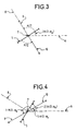
- the antenna 5 is seen from above, it is aligned with a mechanical reference axis 6 taken as the absolute angular reference axis.
- the antenna 5 can rotate around an axis of rotation 7.
- the relative angular reference 8 is normal to one of the elementary antennas with electronic scanning of the antenna 5, the first elementary antenna with electronic scanning for example.
- Each elementary antenna with electronic scanning corresponds to a beam.
- the first elementary antenna with electronic scanning has a beam 9 initially deviated by the relative angle -ad
- the second elementary antenna with electronic scanning has a beam 10 initially deviated by the relative angle ⁇ - ⁇ d .
- Tf being the time necessary for the antenna beam to scan ⁇ , or 180 ° of bearing.
- the beam 9.10 of each elementary antenna with electronic scanning scans half of the scanning carried out by the beam of the antenna 5, ie ⁇ / 2.
- the antenna 5 rotates by an angle equal to ⁇ / 2 - ⁇ d .
- the ratio between the beam scanning angle and the antenna rotation angle is: which corresponds to the ratio between the speeds w 2 and w 1 given by the relation (1).
- the beam 9.10 of each elementary antenna with electronic scanning scans an area equivalent to that scanned between the instants t o and t o + Tf / 2, i.e. an area angle ⁇ / 2.
- the beam 9 of the first elementary antenna with electronic scanning scans an area comprised between the absolute angles ⁇ / 2 - ⁇ d and 3 ⁇ / 2 - ⁇ d and the beam 10 of the second elementary electronic scanning antenna scans an area between the absolute angles 3 ⁇ / 2 - ⁇ d and 5 ⁇ / 2 - ⁇ d .
- the antenna 5 rotates around its axis of rotation 7 by an angle equal to 2 ( ⁇ / 2 - ⁇ d ).
- the antenna radar beam scans 2 ⁇ ; indeed the beam of each elementary antenna with electronic scanning scans ⁇ .
- the radar antenna explored 360 ° of azimuth.
- the radar antenna is offset by an absolute angle 2 ( ⁇ / 2- ⁇ d ).
- the process consists in initializing the electronic pointing of each elementary antenna with electronic scanning at a determined absolute angle ⁇ .
- the value of the angle ⁇ is determined from the number of laps already completed, from relation (1) and the fact that before starting a tour, the beam of each antenna elementary with electronic scanning is depointed by the depointing value maximum.
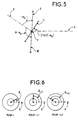
- FIG. 5 illustrates the electronic pointing of each elementary antenna with electronic scanning after the initialization carried out at the end of the 1st round.
- the beam 9 of the first elementary antenna with electronic scanning has a relative angle equal to - ⁇ d .
- the beam 10 of the second elementary antenna with electronic scanning is deviated by a relative angle equal to ⁇ - ⁇ d .
- the antenna 5 rotates around its axis of rotation 7 at a speed w 1 .
- the electronic pointing control points the beam of each elementary antenna with electronic scanning at an angle as a function of time.
- the relative pointing of each beam evolves between the maximum depointing angles of an elementary antenna with electronic scanning.
- Each beam of an elementary antenna with electronic scanning scans an area of angle ⁇ between the instants t o and t o + Tf; the antenna radar beam scans 2 ⁇ .
- the radar antenna is offset by an angle 2 ( ⁇ / 2 - ⁇ d ) relative to its position at time t o .
- the process consists in initializing the electronic pointing of each elementary antenna electronically scanned at a determined angle ⁇ , as described above.
- Figure 6 shows the original offset of successive turns; the turn i takes place with an origin of the turn equal to ⁇ i .
- the origin of the turn j is equal to (j-1) x 2 ( ⁇ / 2 - ⁇ d ) + ( ⁇ / 2 - ⁇ d ).
- the original offset of successive turns can be easily compensable by means of a buffer memory to memorize the whole or part of the data corresponding to a lap and readjust the images radar.
- FIG. 7 A first embodiment of a radar for the implementation of the process according to the invention is shown diagrammatically in FIG. 7.
- the radar comprises a plate 11, an antenna 5, a system servo-control of the plate 12, a rotary joint 13, a switch 14 and a time calculator 15.
- the plate 11 can rotate 360 ° in bearing. It is rotated at a speed w 1 by means of the servo system 12.
- the antenna 5 comprises a first 16 and a second 17 elementary antennas with electronic scanning.
- the first embodiment of the radar is characterized by the particular realization of the first 16 and the second 17 antennas elementary with electronic scanning; each elementary antenna corresponds to a reflective network with which an emission source is associated 18, 19.
- a second embodiment of the radar is characterized by a antenna formed by two active antennas.
- the antenna 5 also comprises a control circuit 20.
- Each reflective grating can be electronically deflected by a maximum angle ad, clockwise and counterclockwise from normal of each reflective grating.
- Each emission source 18, 19 is installed opposite a reflective network 16, 17.
- the switch 14 switches the signal microwave on the first 18 or on the second 19 emission source.
- the control circuit 20 is connected, on the one hand to the first network reflector 16 and, on the other hand, to the second 17 reflecting array. He commands sequentially the diodes of the phase shift cells of the first array reflector 16 and the diodes of the phase shift cells of the second array reflector 1 7.
- the plate 11 carries the antenna 5 which rotates with the plate 11.
- the rotary joint 13 ensures the transmission of the various signals microwave (transmission, reception) between stage 11 and a duplexer (not shown). It also provides the digital control link between the plate 11 and the pointing computer 15.
- the pointing computer 15 controls the electronic pointing of each reflecting array 16, 17.
- the pointing control is such that the scanning of the radar beam is carried out at a speed w 2 on one revolution, w2 checking the relation (1).
- the pointing computer 15 initializes the electronic pointing of each reflecting array 16, 17 at an angle ⁇ i determined as described with reference to FIG. 6.
- each reflective grating can have a horizontal or vertical polarization, the associated source being of the same polarization.
- the antenna allows agility of polarization.
- the first reflective network has horizontal polarization, as well as the associated emission source, and the second reflective grating has vertical polarization, as well as the source associated program.
- a variant of the radar embodiments includes a means associated with the switch. This means determines the polarization of each elementary antenna with electronic scanning. The association with the switch makes it possible to determine at each switching the polarization of the elementary scanning antenna electronic.
Landscapes
- Engineering & Computer Science (AREA)
- Radar, Positioning & Navigation (AREA)
- Remote Sensing (AREA)
- Computer Networks & Wireless Communication (AREA)
- Physics & Mathematics (AREA)
- General Physics & Mathematics (AREA)
- Radar Systems Or Details Thereof (AREA)
- Variable-Direction Aerials And Aerial Arrays (AREA)
Applications Claiming Priority (2)
| Application Number | Priority Date | Filing Date | Title |
|---|---|---|---|
| FR9915624A FR2802304B1 (fr) | 1999-12-10 | 1999-12-10 | Procede d'exploration en gisement d'un radar et radar mettant en oeuvre le procede |
| FR9915624 | 1999-12-10 |
Publications (1)
| Publication Number | Publication Date |
|---|---|
| EP1107019A1 true EP1107019A1 (de) | 2001-06-13 |
Family
ID=9553130
Family Applications (1)
| Application Number | Title | Priority Date | Filing Date |
|---|---|---|---|
| EP00403377A Withdrawn EP1107019A1 (de) | 1999-12-10 | 2000-12-01 | Radargerät und Verfahren zum Suchen in Azimut |
Country Status (4)
| Country | Link |
|---|---|
| US (1) | US6452537B2 (de) |
| EP (1) | EP1107019A1 (de) |
| CA (1) | CA2327378A1 (de) |
| FR (1) | FR2802304B1 (de) |
Cited By (2)
| Publication number | Priority date | Publication date | Assignee | Title |
|---|---|---|---|---|
| US7606442B2 (en) | 2005-01-31 | 2009-10-20 | Hewlett-Packard Development Company, L.P. | Image processing method and apparatus |
| EP2654126A1 (de) | 2012-04-20 | 2013-10-23 | Thales | Mobile Richtantenne mit Polarisierungsschaltung durch Bewegung der Strahlungspaneele |
Families Citing this family (6)
| Publication number | Priority date | Publication date | Assignee | Title |
|---|---|---|---|---|
| WO2003065071A1 (en) * | 2002-02-01 | 2003-08-07 | Per-Arne Isaksen | Radar system and method of operating a radar system |
| CN104122531B (zh) * | 2014-07-18 | 2016-09-28 | 零八一电子集团有限公司 | 自适应处理雷达天线位置振荡的方法 |
| US9851436B2 (en) | 2015-01-05 | 2017-12-26 | Delphi Technologies, Inc. | Radar antenna assembly with panoramic detection |
| US9515390B1 (en) * | 2015-06-11 | 2016-12-06 | The United States Of America As Represented By The Secretary Of The Navy | Discrete phased electromagnetic reflector based on two-state elements |
| CN114609625B (zh) * | 2022-01-18 | 2024-08-30 | 北京锐达仪表有限公司 | 反射式连续旋转雷达扫描装置、测量系统及物料测量方法 |
| CN116540202A (zh) * | 2023-06-05 | 2023-08-04 | 煤炭科学研究总院有限公司 | 一种用于矿山钻孔救援的生命探测定位方法及系统 |
Citations (2)
| Publication number | Priority date | Publication date | Assignee | Title |
|---|---|---|---|---|
| US3648284A (en) * | 1969-08-06 | 1972-03-07 | Westinghouse Electric Corp | Two-face phased array |
| US5841391A (en) * | 1997-06-11 | 1998-11-24 | Itt Manufacturing Enterprises, Inc. | Combined air surveillance and precision approach radar system |
Family Cites Families (5)
| Publication number | Priority date | Publication date | Assignee | Title |
|---|---|---|---|---|
| US3943523A (en) * | 1972-03-07 | 1976-03-09 | Raytheon Company | Airborne multi-mode radiating and receiving system |
| FR2549300B1 (fr) * | 1983-07-13 | 1988-03-25 | Tran Dinh Can | Dispositif de balayage electromecanique notamment pour antenne radar |
| US4667201A (en) * | 1983-11-29 | 1987-05-19 | Nec Corporation | Electronic scanning antenna |
| US5357259A (en) * | 1993-08-13 | 1994-10-18 | Grumman Aerospace Corporation | Aircraft deployable rotating phased array antenna |
| FR2710784B1 (fr) * | 1993-09-28 | 1995-10-27 | Thomson Csf | Procédé de gestion du faisceau d'une antenne tournante à balayage électronique. |
-
1999
- 1999-12-10 FR FR9915624A patent/FR2802304B1/fr not_active Expired - Fee Related
-
2000
- 2000-12-01 EP EP00403377A patent/EP1107019A1/de not_active Withdrawn
- 2000-12-06 CA CA002327378A patent/CA2327378A1/fr not_active Abandoned
- 2000-12-06 US US09/729,825 patent/US6452537B2/en not_active Expired - Fee Related
Patent Citations (2)
| Publication number | Priority date | Publication date | Assignee | Title |
|---|---|---|---|---|
| US3648284A (en) * | 1969-08-06 | 1972-03-07 | Westinghouse Electric Corp | Two-face phased array |
| US5841391A (en) * | 1997-06-11 | 1998-11-24 | Itt Manufacturing Enterprises, Inc. | Combined air surveillance and precision approach radar system |
Non-Patent Citations (2)
| Title |
|---|
| BUCKLER L: "DUAL-USE AIR TRAFFIC CONTROL RADAR", IEEE NATIONAL RADAR CONFERENCE,US,NEW YORK, NY: IEEE, 11 May 1998 (1998-05-11), pages 26 - 31, XP000846895, ISBN: 0-7803-4493-6 * |
| CRONEY J ET AL: "Radar polarization comparisons in sea-clutter suppression by decorrelation and constant false alarm rate receivers", RADIO AND ELECTRONIC ENGINEER, OCT. 1969, UK, vol. 38, no. 4, pages 187 - 198, XP000938469, ISSN: 0033-7722 * |
Cited By (4)
| Publication number | Priority date | Publication date | Assignee | Title |
|---|---|---|---|---|
| US7606442B2 (en) | 2005-01-31 | 2009-10-20 | Hewlett-Packard Development Company, L.P. | Image processing method and apparatus |
| EP2654126A1 (de) | 2012-04-20 | 2013-10-23 | Thales | Mobile Richtantenne mit Polarisierungsschaltung durch Bewegung der Strahlungspaneele |
| FR2989844A1 (fr) * | 2012-04-20 | 2013-10-25 | Thales Sa | Antenne mobile directive a commutation de polarisation par deplacement de panneaux rayonnants |
| US9263801B2 (en) | 2012-04-20 | 2016-02-16 | Thales | Directional mobile antenna with polarization switching by displacement of radiating panels |
Also Published As
| Publication number | Publication date |
|---|---|
| US6452537B2 (en) | 2002-09-17 |
| CA2327378A1 (fr) | 2001-06-10 |
| US20010019314A1 (en) | 2001-09-06 |
| FR2802304A1 (fr) | 2001-06-15 |
| FR2802304B1 (fr) | 2002-03-01 |
Similar Documents
| Publication | Publication Date | Title |
|---|---|---|
| US5093649A (en) | Bessel beam radar system using sequential spatial modulation | |
| EP0002982A1 (de) | Antenne mit konischer Abtastung für Verfolgungsradar | |
| EP3491408B1 (de) | Verfahren und system zur schätzung der richtung eines satelliten in der transferphase von einer ersten umlaufbahn zu einer missionsumlaufbahn | |
| CA3161114A1 (fr) | Procede de poursuite d'un objet spatial a l'aide de systemes radar et lidar embarques | |
| EP1107019A1 (de) | Radargerät und Verfahren zum Suchen in Azimut | |
| FR2639718A1 (fr) | Radar ultrasonique a visee laterale notamment embarque dans un vehicule sous-marin se deplacant au-dessus d'une surface de visee | |
| WO1986000998A1 (en) | Antenna tracking system using sequential lobing | |
| EP0454582A1 (de) | Rundstrahl-Funkpeilantennensystem | |
| FR2680581A1 (fr) | Systeme de radar de surveillance secondaire. | |
| FR3027408A1 (fr) | Procede radar de surveillance maritime et dispositifs radar associes | |
| FR2857786A1 (fr) | Procede de commande et systeme a antenne radar | |
| FR2619928A1 (fr) | Dispositifs radars perfectionnes | |
| FR2793885A1 (fr) | Procede et dispositif de guidage electromagnetique, appliques notamment a la poursuite de cibles | |
| FR2986334A1 (fr) | Instrument radar satellitaire pour la surveillance maritime | |
| EP3111247A1 (de) | Zur ausrüstung eines küstenüberwachungssystems geeignete radarvorrichtung und küstenüberwachungssystem mit solch einer vorrichtung | |
| CA2706761C (fr) | Antenne a reflecteur a flexibilite de couverture et de frequence et satellite comportant une telle antenne | |
| EP3497747A1 (de) | Seitenrollgesteuerter radar zur autonomen lenkung einer plattform und selbstlenkender flugkörper mit solch einem radar | |
| EP1320145A1 (de) | Verfahren und Vorrichtung zum Ausrichten einer Antenne | |
| WO2000026693A1 (fr) | Radar maritime | |
| EP0429349A1 (de) | Verfahren und Einrichtung zur Übertragung breitbandiger Signale mit Hilfe einer mobilen Ausrüstung | |
| FR2624981A1 (fr) | Dispositif et procede de radionavigation pour aeronef a voilure tournante | |
| EP1522871B1 (de) | Radar mit synthetischen Peilkanälen | |
| FR2779873A1 (fr) | Antenne a balayage electronique a polarisation | |
| EP4671823A1 (de) | Verfahren zum betreiben eines sensorradars und sensorradar dafür | |
| FR3164023A1 (fr) | Procédé de fonctionnement d'un radar de détection et radar de détection associé |
Legal Events
| Date | Code | Title | Description |
|---|---|---|---|
| PUAI | Public reference made under article 153(3) epc to a published international application that has entered the european phase |
Free format text: ORIGINAL CODE: 0009012 |
|
| AK | Designated contracting states |
Kind code of ref document: A1 Designated state(s): DE FR GB IT SE |
|
| AX | Request for extension of the european patent |
Free format text: AL;LT;LV;MK;RO;SI |
|
| RAP1 | Party data changed (applicant data changed or rights of an application transferred) |
Owner name: THALES |
|
| 17P | Request for examination filed |
Effective date: 20011127 |
|
| AKX | Designation fees paid |
Free format text: DE FR GB IT SE |
|
| RBV | Designated contracting states (corrected) |
Designated state(s): DE FR GB IT SE |
|
| STAA | Information on the status of an ep patent application or granted ep patent |
Free format text: STATUS: THE APPLICATION IS DEEMED TO BE WITHDRAWN |
|
| 18D | Application deemed to be withdrawn |
Effective date: 20040701 |