EP1107029A2 - Méthode de fabrication de guides d'onde optiques comprenant des fibres optiques - Google Patents
Méthode de fabrication de guides d'onde optiques comprenant des fibres optiques Download PDFInfo
- Publication number
- EP1107029A2 EP1107029A2 EP00811056A EP00811056A EP1107029A2 EP 1107029 A2 EP1107029 A2 EP 1107029A2 EP 00811056 A EP00811056 A EP 00811056A EP 00811056 A EP00811056 A EP 00811056A EP 1107029 A2 EP1107029 A2 EP 1107029A2
- Authority
- EP
- European Patent Office
- Prior art keywords
- fiber
- phase shift
- segment
- optical fiber
- relaxation zone
- Prior art date
- Legal status (The legal status is an assumption and is not a legal conclusion. Google has not performed a legal analysis and makes no representation as to the accuracy of the status listed.)
- Granted
Links
Images

Classifications
-
- G—PHYSICS
- G02—OPTICS
- G02B—OPTICAL ELEMENTS, SYSTEMS OR APPARATUS
- G02B6/00—Light guides; Structural details of arrangements comprising light guides and other optical elements, e.g. couplings
- G02B6/24—Coupling light guides
- G02B6/255—Splicing of light guides, e.g. by fusion or bonding
- G02B6/2551—Splicing of light guides, e.g. by fusion or bonding using thermal methods, e.g. fusion welding by arc discharge, laser beam, plasma torch
-
- C—CHEMISTRY; METALLURGY
- C03—GLASS; MINERAL OR SLAG WOOL
- C03B—MANUFACTURE, SHAPING, OR SUPPLEMENTARY PROCESSES
- C03B37/00—Manufacture or treatment of flakes, fibres, or filaments from softened glass, minerals, or slags
- C03B37/10—Non-chemical treatment
- C03B37/14—Re-forming fibres or filaments, i.e. changing their shape
- C03B37/15—Re-forming fibres or filaments, i.e. changing their shape with heat application, e.g. for making optical fibres
-
- G—PHYSICS
- G02—OPTICS
- G02B—OPTICAL ELEMENTS, SYSTEMS OR APPARATUS
- G02B6/00—Light guides; Structural details of arrangements comprising light guides and other optical elements, e.g. couplings
- G02B6/10—Light guides; Structural details of arrangements comprising light guides and other optical elements, e.g. couplings of the optical waveguide type
- G02B6/105—Light guides; Structural details of arrangements comprising light guides and other optical elements, e.g. couplings of the optical waveguide type having optical polarisation effects
-
- C—CHEMISTRY; METALLURGY
- C03—GLASS; MINERAL OR SLAG WOOL
- C03B—MANUFACTURE, SHAPING, OR SUPPLEMENTARY PROCESSES
- C03B2203/00—Fibre product details, e.g. structure, shape
- C03B2203/10—Internal structure or shape details
- C03B2203/18—Axial perturbations, e.g. in refractive index or composition
-
- C—CHEMISTRY; METALLURGY
- C03—GLASS; MINERAL OR SLAG WOOL
- C03B—MANUFACTURE, SHAPING, OR SUPPLEMENTARY PROCESSES
- C03B2203/00—Fibre product details, e.g. structure, shape
- C03B2203/10—Internal structure or shape details
- C03B2203/18—Axial perturbations, e.g. in refractive index or composition
- C03B2203/20—Axial perturbations, e.g. in refractive index or composition helical
-
- C—CHEMISTRY; METALLURGY
- C03—GLASS; MINERAL OR SLAG WOOL
- C03B—MANUFACTURE, SHAPING, OR SUPPLEMENTARY PROCESSES
- C03B2203/00—Fibre product details, e.g. structure, shape
- C03B2203/36—Dispersion modified fibres, e.g. wavelength or polarisation shifted, flattened or compensating fibres (DSF, DFF, DCF)
-
- G—PHYSICS
- G02—OPTICS
- G02B—OPTICAL ELEMENTS, SYSTEMS OR APPARATUS
- G02B6/00—Light guides; Structural details of arrangements comprising light guides and other optical elements, e.g. couplings
- G02B6/24—Coupling light guides
- G02B6/26—Optical coupling means
- G02B6/34—Optical coupling means utilising prism or grating
Definitions
- the invention relates to a method for producing a fiber optic Waveguide and a fiber optic waveguide with a base segment and a phase shift segment according to the preamble of Claims 1 and 9.
- a generic fiber optic waveguide with a base segment and a phase shift segment is for example from EP-A-0'856'737 known where it is used in a magneto-optical current sensor.
- This Waveguide has two polarization-maintaining basic fibers with elliptical Cores, called lead fiber and return fiber, as well as one arranged between these two fibers in the form of a coil around an electrical one Conductor wound sensor fiber with a round core.
- Linearly polarized waves that propagate in the feed fiber become orthogonal when transitioning into the delay element
- Decomposed polarization components that are parallel to the main axes of the core of the delay element are aligned.
- the length of the ⁇ / 4 delay element is chosen so that the two Polarization components at its end due to birefringence one have an optical phase difference of 90 °. That from the delay element emerging light is then circularly polarized.
- first delay element made of linearly polarized waves of the feed fiber generate circularly polarized waves that propagate in the sensor fiber can, and again linearly polarized by a second delay element Convert waves back whose polarization is parallel to a major axis of the elliptical core of the return fiber lies so that it is in this can spread.
- Splicing devices which determine the angular orientation of fiber cores by automatically scanning the fibers from the side. This method gives good results for fibers with stress-induced birefringence. However, it is insufficient for the fibers described above, whose Birefringence is based on an elliptical nucleus. This is particularly true Fibers, which are designed for small wavelengths of maximum 850 nm, since the elliptical fiber cores are very small and the splicer their orientation cannot recognize with sufficient accuracy.
- an optical fiber is defined around a defined one Angle twisted and a zone of fiber warmed until the torsion in it Zone triggers so that a basic segment is adjacent to this zone on one side and on the other hand a phase shift segment respectively Segment with an orientation corresponding to the one to be achieved Phase shift segment arises.
- a complicated alignment of two fibers is not necessary, since it is caused by one simple torsion around an optical axis or longitudinal axis of a Fiber is replaced. Local heating of the fiber material dissolves the Torsion. A relaxation zone is created within the fiber, which the Fiber divided into two segments, the fiber cores of which around the torsion angle are aligned with each other.
- both a basic segment and a phase shift segment having, base segment and phase shift segment Have cores that are at a defined angle to each other are aligned, and being the two segments heated by the and again frozen relaxation zone are separated from each other.
- the core of the base segment and the displacement segment have the same shape, namely that of the core of the optical fiber.
- the optical fiber is with a second optical fiber connected, wherein both fibers are twisted together.
- the Relaxation zone is chosen so that it is at a defined distance to a junction of the two fibers.
- the location of the relaxation zone is chosen arbitrarily. Only after Solidification of this zone becomes the optical fiber at a defined distance broken to a phase shift segment in its needed To form length. A second fiber can then be especially with different core, spliced.
- the polarization state or the phase shift segment can be achieved by the birefringence of the phase shift segment is adjusted by heating.
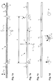
- Two fibers 1, 2 are tensioned in holders 5, 6 of a fiber splicer. Except for two electrodes 7, the splicer is not shown any further.
- Example shown here are two fibers 1, 2 with different cores used, the first fiber 1 shown in the picture on the left an elliptical Has core K for the propagation of linearly polarized light waves and the The second fiber 2 shown on the right has a round core K 'for the propagation of has circularly polarized light waves.
- the polarizations P are in the Figure la shown with arrows.
- the cores K, K ' can be seen in FIG. 1d.
- the fiber is used in a magneto-optical sensor at the beginning mentioned type, the first fiber 1 forms a basic fiber and the second Fiber 2 is a sensor fiber.
- connection point 3 is formed.
- a fiber composite is created, which has a section 4 clamped between two brackets 5, 6 has, the section 4 includes the connection point 3.
- the length d section 4 is typically 5-15 cm. This optical fiber composite is shown in Figure la.
- At least one of the two brackets 5, 6 is designed as a rotating bracket, with which the clamped section 4 about an optical axis or longitudinal axis of the fiber composite is rotatable.
- this is the second holder 6, which encloses the second fiber 2.
- Section 4 or the fiber composite is now at least almost twisted at a predefined angle a and in this torsion position kept fixed.
- the fiber is for use in a magneto-optical Sensor of the type mentioned at the beginning, the angle a is at least approximately preferably exactly 45 °.
- the clamped section 4 is now locally heated, preferably by means of the Arc of the splicer.
- the brackets 5,6 with the clamped Fiber by a defined distance in the longitudinal direction of the fiber composite moved so that the electrodes 7 on the first fiber 1, the basic fiber, demonstrate.
- the displacement distance or the distance L to the splice point 3 depends on the type of phase shift segment 12 to be achieved as this distance is the length of the resulting phase shift segment 12 forms. Generally the length is at least a multiple of a fraction a beat length of orthogonal polarization modes of the first fiber 1.
- the distance 1 is at least approximately a quarter of the beat length, in the case of a ⁇ / 2 or ⁇ / 8 delay element, it is half or relative an eighth of it.
- the is Beat length for commercially available fibers with an elliptical core about 4 mm.
- the length ratio of the two main axes of the elliptical Kerns is 2: 1.
- a relaxation zone 13 within the first fiber the length of which is preferably 10-90 ⁇ m.
- This relaxation zone 13 is heated until the torsion dissolves in it. there the fiber is preferably softened but not melted.
- the relaxation zone 13 becomes active or passively solidified, the fixation of the torsion position up to Solidification of the relaxation zone 13 is maintained. Both Usually used materials solidify the zone within a few Seconds after the arc goes out by itself.
- the relaxation zone 13 of this fiber optic waveguide according to the invention has a core, which is no longer exactly elliptical and itself thus from the cores K of the base segment 11 or phase shift segment 12 differs. This depends among other things on the Diffusion of the doping of the nucleus, usually germanium atoms, in the Heating the relaxation zone 13 together.
- FIGS. 2a to 2c show a second variant of the method according to the invention shown.
- the optical fiber 1 is between two brackets 5.6 of the splicer clamped to the defined Torsion angle a rotated with respect to the fiber longitudinal axis and then on any place of the clamped section 4 by means of the arc heated, so that again the relaxation zone 13 is formed, in which the Torsion is released, as shown in Figure 2a. Also arise here right and left of the relaxation zone 13 segments with different directed cores. After the relaxation zone 13 solidifies, the Brackets 5.6 released and the optical fiber 1 is at a point which in a defined distance L from the relaxation zone 13 is broken, as can be seen from Figure 2b.
- the distance corresponds to that Length L of the phase shift segment 12 to be achieved and thus depends again depending on its type.
- the fiber-optic waveguide according to the invention can now be attached to this broken one Splice on a second fiber 2 at the end 14.
- FIG. 2c In the example shown here according to FIG. 2c, in turn, is used to generate a waveguide for a magneto-optical current sensor spliced a sensor fiber 2 with a round core.
- the cores K, K 'of the two fibers are shown in Figure 2d.
- the method according to the invention allows a fine correction of the polarization state, which can be used in all variants of the process. Because of of tolerances of the optical fiber 1 as well as the splicer possible that the phase shift between the two orthogonal polarization components the phase shift segment 12 from the desired Value differs. In the example with the ⁇ / 4 displacement segment, this means that the value is not 90 °. To have a correction option, now the length of the phase shift segment 12 and thus the distance L. choose slightly longer than a theoretical setpoint so that the resulting Phase shift is also greater than 90 °. The light at the exit of the Phase shift segment 12 is thus slightly elliptically polarized.
- the birefringence of the phase shift segment 12 can now be if necessary, repeated heating of the phase shift segment Decrease 12 in small steps until the polarization state at the output of the segment lies within the desired tolerance, that means here is circular.
- the heating is again preferably carried out in the arc of the Splicer.
- the explanation of this process is as follows: When heating up diffuse dopings from the elliptical fiber core into the fiber cladding. The jump in the refractive index between the core and the cladding becomes smaller or smeared, which results in reduced birefringence Has.
- polarization-maintaining fibers were used as the basic fibers Fibers with elliptical cores are used.
- the inventive the method is not limited to such fibers, for example lets fibers with stress-induced birefringence are also used.
Landscapes
- Physics & Mathematics (AREA)
- Engineering & Computer Science (AREA)
- Plasma & Fusion (AREA)
- General Physics & Mathematics (AREA)
- Optics & Photonics (AREA)
- Chemical & Material Sciences (AREA)
- Manufacturing & Machinery (AREA)
- Geochemistry & Mineralogy (AREA)
- General Life Sciences & Earth Sciences (AREA)
- Life Sciences & Earth Sciences (AREA)
- Materials Engineering (AREA)
- Organic Chemistry (AREA)
- Optical Fibers, Optical Fiber Cores, And Optical Fiber Bundles (AREA)
- Mechanical Coupling Of Light Guides (AREA)
- Optical Integrated Circuits (AREA)
- Optical Transform (AREA)
- Investigating Or Analysing Materials By Optical Means (AREA)
- Surface Treatment Of Glass Fibres Or Filaments (AREA)
- Light Guides In General And Applications Therefor (AREA)
Applications Claiming Priority (2)
| Application Number | Priority Date | Filing Date | Title |
|---|---|---|---|
| DE19958600 | 1999-12-06 | ||
| DE19958600A DE19958600A1 (de) | 1999-12-06 | 1999-12-06 | Verfahren zur Herstellung eines faseroptischen Wellenleiters |
Publications (3)
| Publication Number | Publication Date |
|---|---|
| EP1107029A2 true EP1107029A2 (fr) | 2001-06-13 |
| EP1107029A3 EP1107029A3 (fr) | 2003-12-10 |
| EP1107029B1 EP1107029B1 (fr) | 2008-01-23 |
Family
ID=7931492
Family Applications (1)
| Application Number | Title | Priority Date | Filing Date |
|---|---|---|---|
| EP00811056A Expired - Lifetime EP1107029B1 (fr) | 1999-12-06 | 2000-11-09 | Méthode de fabrication de guides d'onde optiques comprenant des fibres optiques pour un capteur |
Country Status (5)
| Country | Link |
|---|---|
| US (1) | US6628869B2 (fr) |
| EP (1) | EP1107029B1 (fr) |
| AT (1) | ATE384968T1 (fr) |
| CA (1) | CA2326960C (fr) |
| DE (2) | DE19958600A1 (fr) |
Cited By (5)
| Publication number | Priority date | Publication date | Assignee | Title |
|---|---|---|---|---|
| WO2003071290A1 (fr) * | 2001-08-31 | 2003-08-28 | Abb Research Ltd | Procede pour realiser une tete de detection pour des capteurs de courant optiques |
| EP2306211A1 (fr) | 2009-09-30 | 2011-04-06 | ABB Research Ltd. | Procédé de fabrication d'un capteur de courant à fibre optique doté d'une compensation inhérente de la température de l'effet de Faraday |
| EP2306212A1 (fr) | 2009-09-30 | 2011-04-06 | ABB Research Ltd. | Capteur de champ magnétique ou de courant à fibre optique à température compensée doté d'une insensibilité aux variations des paramètres du capteur |
| US9310399B2 (en) | 2009-12-11 | 2016-04-12 | Abb Research Ltd | Fiber-optic current sensing using a sensor with exchangeable sub-modules |
| US10859607B2 (en) | 2013-12-20 | 2020-12-08 | Abb Power Grids Switzerland Ag | Fiber-optic sensor and method |
Families Citing this family (2)
| Publication number | Priority date | Publication date | Assignee | Title |
|---|---|---|---|---|
| DE10352590A1 (de) * | 2002-11-12 | 2004-05-27 | Toptica Photonics Ag | Verfahren zum Herstellen einer optischen Faser mit einer Auskoppelstelle für Streulicht, Verwendung einer optischen Faser und Vorrichtung zum Überwachen von in einer optischen Faser geführter Lichtleistung |
| ES2325621T3 (es) * | 2003-12-30 | 2009-09-10 | Prysmian S.P.A. | Enlace de fibra optica de baja dispersion de modo de polarizacion (pmd) y procedimiento para su fabricacion. |
Family Cites Families (7)
| Publication number | Priority date | Publication date | Assignee | Title |
|---|---|---|---|---|
| US4603941A (en) * | 1982-09-27 | 1986-08-05 | Agency Of Industrial Science And Technology | Polarization-maintaining fiber system and method of manufacturing the same |
| FR2537731B1 (fr) * | 1982-12-10 | 1986-01-17 | Thomson Csf | Procede de fabrication d'une fibre conservant la polarisation circulaire et dispositif mettant en oeuvre ce procede |
| US4529262A (en) * | 1983-05-09 | 1985-07-16 | At&T Bell Laboratories | Inline optical fiber attentuator |
| JPH05297238A (ja) | 1992-04-17 | 1993-11-12 | Fujikura Ltd | 偏波保持光ファイバ融着接続における軸合わせ方法 |
| DE19703128A1 (de) * | 1997-01-29 | 1998-08-06 | Abb Research Ltd | Magnetooptischer Stromsensor |
| US6023331A (en) * | 1997-06-19 | 2000-02-08 | The Texas A&M University System | Fiber optic interferometric sensor and method by adding controlled amounts of circular birefringence in the sensing fiber |
| CA2362140C (fr) * | 1999-02-11 | 2009-12-15 | Richard B. Dyott | Transformateur de polarisation et capteur de courant utilisant celui-ci |
-
1999
- 1999-12-06 DE DE19958600A patent/DE19958600A1/de not_active Withdrawn
-
2000
- 2000-11-09 DE DE50014926T patent/DE50014926D1/de not_active Expired - Lifetime
- 2000-11-09 AT AT00811056T patent/ATE384968T1/de not_active IP Right Cessation
- 2000-11-09 EP EP00811056A patent/EP1107029B1/fr not_active Expired - Lifetime
- 2000-11-28 CA CA2326960A patent/CA2326960C/fr not_active Expired - Fee Related
- 2000-11-30 US US09/725,800 patent/US6628869B2/en not_active Expired - Lifetime
Cited By (5)
| Publication number | Priority date | Publication date | Assignee | Title |
|---|---|---|---|---|
| WO2003071290A1 (fr) * | 2001-08-31 | 2003-08-28 | Abb Research Ltd | Procede pour realiser une tete de detection pour des capteurs de courant optiques |
| EP2306211A1 (fr) | 2009-09-30 | 2011-04-06 | ABB Research Ltd. | Procédé de fabrication d'un capteur de courant à fibre optique doté d'une compensation inhérente de la température de l'effet de Faraday |
| EP2306212A1 (fr) | 2009-09-30 | 2011-04-06 | ABB Research Ltd. | Capteur de champ magnétique ou de courant à fibre optique à température compensée doté d'une insensibilité aux variations des paramètres du capteur |
| US9310399B2 (en) | 2009-12-11 | 2016-04-12 | Abb Research Ltd | Fiber-optic current sensing using a sensor with exchangeable sub-modules |
| US10859607B2 (en) | 2013-12-20 | 2020-12-08 | Abb Power Grids Switzerland Ag | Fiber-optic sensor and method |
Also Published As
| Publication number | Publication date |
|---|---|
| US20010002944A1 (en) | 2001-06-07 |
| DE50014926D1 (de) | 2008-03-13 |
| CA2326960C (fr) | 2011-04-19 |
| DE19958600A1 (de) | 2001-06-07 |
| EP1107029B1 (fr) | 2008-01-23 |
| ATE384968T1 (de) | 2008-02-15 |
| US6628869B2 (en) | 2003-09-30 |
| EP1107029A3 (fr) | 2003-12-10 |
| CA2326960A1 (fr) | 2001-06-06 |
Similar Documents
| Publication | Publication Date | Title |
|---|---|---|
| DE69628373T2 (de) | Optischer Koppler mit faseroptischen Steckerstiften | |
| DE2931474C2 (de) | Nicht-reziproke optische Vorrichtung | |
| DE69421166T2 (de) | Bestimmung des winkelversutzes zwischen optischen fasern mit optischer, axialer asymmetrie und ausrichtung und spleissen von solchen fasern | |
| DE69215897T2 (de) | Fiberoptisches dämpfungsglied | |
| DE69225037T2 (de) | Verfahren zur Begrenzung der Kupplungsverluste zwischen einer optischen Monomodefaser und einem optischen System mit einem niedrigeren Modenfleckdurchmesser oder zwischen zwei Monomodefasern mit gleichem Modenfleckdurchmesser | |
| DE3782537T2 (de) | Richtkoppler. | |
| EP0012189B1 (fr) | Elément coupleur pour dériver une fraction de lumière d'un guide d'ondes optique comprenant une fibre entourée d'une gaine | |
| DE69630090T2 (de) | Faseroptische Dämpfungsvorrichtung | |
| DE68914349T2 (de) | Methode zur Herstellung eines optischen Verzweigungs- und Kopplungselements. | |
| WO2011124671A1 (fr) | Procédé et système pour générer un faisceau laser présentant différentes caractéristiques de profil de faisceau au moyen d'une fibre à plusieurs gaines | |
| DE69418141T2 (de) | Optische Faserelemente | |
| EP0970395A1 (fr) | Microlentilles integrees a des fibres et coupleurs optiques a reseau de bragg situe dans la fibre; spectrometres et multiplexeurs ainsi constitues | |
| DE3920416A1 (de) | Optisches bauteil, und verfahren zu seiner herstellung | |
| DE2848539A1 (de) | Faseroptische kopplungsvorrichtung | |
| DE2923851A1 (de) | Kupplung fuer lichtleitkabel | |
| DE69524801T2 (de) | Optische Anordnung zum Koppeln einer optischen Faser mit einem kreisförmigen Modenfeld und eines optoelektronischen Wandlers mit einem elliptischen Modenfeld sowie deren Herstellungsverfahren | |
| EP1107029B1 (fr) | Méthode de fabrication de guides d'onde optiques comprenant des fibres optiques pour un capteur | |
| DE69634866T2 (de) | Fiberoptisches Dämpfungsglied | |
| WO2004099856A1 (fr) | Dispositif de séparation de rayons lumineux | |
| EP0048855A2 (fr) | Elément de réglage de la transmission de lumière entre des guides d'ondes optiques | |
| DE112021000271T5 (de) | Faser-Divergenzbeschränkungsvorrichtung | |
| DE4243342C2 (de) | Lichtwellenleiter-Verzweiger oder -Combiner, Bauelemente hierfür sowie Verfahren zur Herstellung solcher Bauelemente | |
| DE60218624T2 (de) | Vorrichtung zur Abstimmung der Wellenlänge einer Lichtquelle | |
| DE3930035A1 (de) | Verfahren zur herstellung eines optischen verschmelzkopplers und danach hergestellter koppler | |
| DE69430756T2 (de) | Faseroptischer koppler |
Legal Events
| Date | Code | Title | Description |
|---|---|---|---|
| PUAI | Public reference made under article 153(3) epc to a published international application that has entered the european phase |
Free format text: ORIGINAL CODE: 0009012 |
|
| AK | Designated contracting states |
Kind code of ref document: A2 Designated state(s): AT BE CH CY DE DK ES FI FR GB GR IE IT LI LU MC NL PT SE TR |
|
| AX | Request for extension of the european patent |
Free format text: AL;LT;LV;MK;RO;SI |
|
| PUAL | Search report despatched |
Free format text: ORIGINAL CODE: 0009013 |
|
| AK | Designated contracting states |
Kind code of ref document: A3 Designated state(s): AT BE CH CY DE DK ES FI FR GB GR IE IT LI LU MC NL PT SE TR |
|
| AX | Request for extension of the european patent |
Extension state: AL LT LV MK RO SI |
|
| RIC1 | Information provided on ipc code assigned before grant |
Ipc: 7G 02B 6/10 B Ipc: 7G 02B 6/27 A |
|
| 17P | Request for examination filed |
Effective date: 20040515 |
|
| 17Q | First examination report despatched |
Effective date: 20040611 |
|
| AKX | Designation fees paid |
Designated state(s): AT BE CH CY DE DK ES FI FR GB GR IE IT LI LU MC NL PT SE TR |
|
| RTI1 | Title (correction) |
Free format text: METHOD OF FABRICATION OF AN OPTICAL FIBRE WAVEGUIDE FOR A SENSOR |
|
| GRAP | Despatch of communication of intention to grant a patent |
Free format text: ORIGINAL CODE: EPIDOSNIGR1 |
|
| GRAS | Grant fee paid |
Free format text: ORIGINAL CODE: EPIDOSNIGR3 |
|
| GRAA | (expected) grant |
Free format text: ORIGINAL CODE: 0009210 |
|
| AK | Designated contracting states |
Kind code of ref document: B1 Designated state(s): AT BE CH CY DE DK ES FI FR GB GR IE IT LI LU MC NL PT SE TR |
|
| REG | Reference to a national code |
Ref country code: GB Ref legal event code: FG4D Free format text: NOT ENGLISH |
|
| REG | Reference to a national code |
Ref country code: CH Ref legal event code: EP |
|
| REG | Reference to a national code |
Ref country code: IE Ref legal event code: FG4D Free format text: LANGUAGE OF EP DOCUMENT: GERMAN |
|
| REF | Corresponds to: |
Ref document number: 50014926 Country of ref document: DE Date of ref document: 20080313 Kind code of ref document: P |
|
| REG | Reference to a national code |
Ref country code: CH Ref legal event code: NV Representative=s name: ABB SCHWEIZ AG INTELLECTUAL PROPERTY (CH-LC/IP) |
|
| GBT | Gb: translation of ep patent filed (gb section 77(6)(a)/1977) |
Effective date: 20080428 |
|
| NLV1 | Nl: lapsed or annulled due to failure to fulfill the requirements of art. 29p and 29m of the patents act | ||
| PG25 | Lapsed in a contracting state [announced via postgrant information from national office to epo] |
Ref country code: FI Free format text: LAPSE BECAUSE OF FAILURE TO SUBMIT A TRANSLATION OF THE DESCRIPTION OR TO PAY THE FEE WITHIN THE PRESCRIBED TIME-LIMIT Effective date: 20080123 Ref country code: ES Free format text: LAPSE BECAUSE OF FAILURE TO SUBMIT A TRANSLATION OF THE DESCRIPTION OR TO PAY THE FEE WITHIN THE PRESCRIBED TIME-LIMIT Effective date: 20080504 |
|
| ET | Fr: translation filed | ||
| PG25 | Lapsed in a contracting state [announced via postgrant information from national office to epo] |
Ref country code: PT Free format text: LAPSE BECAUSE OF FAILURE TO SUBMIT A TRANSLATION OF THE DESCRIPTION OR TO PAY THE FEE WITHIN THE PRESCRIBED TIME-LIMIT Effective date: 20080623 |
|
| REG | Reference to a national code |
Ref country code: IE Ref legal event code: FD4D |
|
| PG25 | Lapsed in a contracting state [announced via postgrant information from national office to epo] |
Ref country code: NL Free format text: LAPSE BECAUSE OF FAILURE TO SUBMIT A TRANSLATION OF THE DESCRIPTION OR TO PAY THE FEE WITHIN THE PRESCRIBED TIME-LIMIT Effective date: 20080123 Ref country code: IE Free format text: LAPSE BECAUSE OF FAILURE TO SUBMIT A TRANSLATION OF THE DESCRIPTION OR TO PAY THE FEE WITHIN THE PRESCRIBED TIME-LIMIT Effective date: 20080123 Ref country code: DK Free format text: LAPSE BECAUSE OF FAILURE TO SUBMIT A TRANSLATION OF THE DESCRIPTION OR TO PAY THE FEE WITHIN THE PRESCRIBED TIME-LIMIT Effective date: 20080123 Ref country code: SE Free format text: LAPSE BECAUSE OF FAILURE TO SUBMIT A TRANSLATION OF THE DESCRIPTION OR TO PAY THE FEE WITHIN THE PRESCRIBED TIME-LIMIT Effective date: 20080423 |
|
| PLBE | No opposition filed within time limit |
Free format text: ORIGINAL CODE: 0009261 |
|
| STAA | Information on the status of an ep patent application or granted ep patent |
Free format text: STATUS: NO OPPOSITION FILED WITHIN TIME LIMIT |
|
| 26N | No opposition filed |
Effective date: 20081024 |
|
| BERE | Be: lapsed |
Owner name: ABB RESEARCH LTD. Effective date: 20081130 |
|
| PG25 | Lapsed in a contracting state [announced via postgrant information from national office to epo] |
Ref country code: MC Free format text: LAPSE BECAUSE OF NON-PAYMENT OF DUE FEES Effective date: 20081130 |
|
| PG25 | Lapsed in a contracting state [announced via postgrant information from national office to epo] |
Ref country code: CY Free format text: LAPSE BECAUSE OF FAILURE TO SUBMIT A TRANSLATION OF THE DESCRIPTION OR TO PAY THE FEE WITHIN THE PRESCRIBED TIME-LIMIT Effective date: 20080123 |
|
| PG25 | Lapsed in a contracting state [announced via postgrant information from national office to epo] |
Ref country code: BE Free format text: LAPSE BECAUSE OF NON-PAYMENT OF DUE FEES Effective date: 20081130 |
|
| PG25 | Lapsed in a contracting state [announced via postgrant information from national office to epo] |
Ref country code: AT Free format text: LAPSE BECAUSE OF NON-PAYMENT OF DUE FEES Effective date: 20081109 |
|
| PG25 | Lapsed in a contracting state [announced via postgrant information from national office to epo] |
Ref country code: LU Free format text: LAPSE BECAUSE OF NON-PAYMENT OF DUE FEES Effective date: 20081109 |
|
| PG25 | Lapsed in a contracting state [announced via postgrant information from national office to epo] |
Ref country code: TR Free format text: LAPSE BECAUSE OF FAILURE TO SUBMIT A TRANSLATION OF THE DESCRIPTION OR TO PAY THE FEE WITHIN THE PRESCRIBED TIME-LIMIT Effective date: 20080123 |
|
| PG25 | Lapsed in a contracting state [announced via postgrant information from national office to epo] |
Ref country code: GR Free format text: LAPSE BECAUSE OF FAILURE TO SUBMIT A TRANSLATION OF THE DESCRIPTION OR TO PAY THE FEE WITHIN THE PRESCRIBED TIME-LIMIT Effective date: 20080424 |
|
| PGFP | Annual fee paid to national office [announced via postgrant information from national office to epo] |
Ref country code: CH Payment date: 20131121 Year of fee payment: 14 Ref country code: GB Payment date: 20131120 Year of fee payment: 14 |
|
| PGFP | Annual fee paid to national office [announced via postgrant information from national office to epo] |
Ref country code: IT Payment date: 20131126 Year of fee payment: 14 |
|
| PGFP | Annual fee paid to national office [announced via postgrant information from national office to epo] |
Ref country code: FR Payment date: 20141119 Year of fee payment: 15 Ref country code: DE Payment date: 20141119 Year of fee payment: 15 |
|
| REG | Reference to a national code |
Ref country code: CH Ref legal event code: PL |
|
| GBPC | Gb: european patent ceased through non-payment of renewal fee |
Effective date: 20141109 |
|
| PG25 | Lapsed in a contracting state [announced via postgrant information from national office to epo] |
Ref country code: LI Free format text: LAPSE BECAUSE OF NON-PAYMENT OF DUE FEES Effective date: 20141130 Ref country code: CH Free format text: LAPSE BECAUSE OF NON-PAYMENT OF DUE FEES Effective date: 20141130 |
|
| PG25 | Lapsed in a contracting state [announced via postgrant information from national office to epo] |
Ref country code: GB Free format text: LAPSE BECAUSE OF NON-PAYMENT OF DUE FEES Effective date: 20141109 |
|
| PG25 | Lapsed in a contracting state [announced via postgrant information from national office to epo] |
Ref country code: IT Free format text: LAPSE BECAUSE OF NON-PAYMENT OF DUE FEES Effective date: 20141109 |
|
| REG | Reference to a national code |
Ref country code: DE Ref legal event code: R119 Ref document number: 50014926 Country of ref document: DE |
|
| REG | Reference to a national code |
Ref country code: FR Ref legal event code: ST Effective date: 20160729 |
|
| PG25 | Lapsed in a contracting state [announced via postgrant information from national office to epo] |
Ref country code: DE Free format text: LAPSE BECAUSE OF NON-PAYMENT OF DUE FEES Effective date: 20160601 |
|
| PG25 | Lapsed in a contracting state [announced via postgrant information from national office to epo] |
Ref country code: FR Free format text: LAPSE BECAUSE OF NON-PAYMENT OF DUE FEES Effective date: 20151130 |