EP1107087A1 - Steuervorrichtung mit mehreren stabilen Positionen, ins besondere fur Zigarrenanzünder - Google Patents
Steuervorrichtung mit mehreren stabilen Positionen, ins besondere fur Zigarrenanzünder Download PDFInfo
- Publication number
- EP1107087A1 EP1107087A1 EP00403313A EP00403313A EP1107087A1 EP 1107087 A1 EP1107087 A1 EP 1107087A1 EP 00403313 A EP00403313 A EP 00403313A EP 00403313 A EP00403313 A EP 00403313A EP 1107087 A1 EP1107087 A1 EP 1107087A1
- Authority
- EP
- European Patent Office
- Prior art keywords
- cam
- finger
- button
- axis
- cigar lighter
- Prior art date
- Legal status (The legal status is an assumption and is not a legal conclusion. Google has not performed a legal analysis and makes no representation as to the accuracy of the status listed.)
- Granted
Links
- 235000019506 cigar Nutrition 0.000 title claims description 21
- 238000010438 heat treatment Methods 0.000 claims description 18
- 235000019504 cigarettes Nutrition 0.000 description 16
- 210000002445 nipple Anatomy 0.000 description 15
- 230000000694 effects Effects 0.000 description 5
- 239000000284 extract Substances 0.000 description 3
- 238000006073 displacement reaction Methods 0.000 description 2
- 229920003023 plastic Polymers 0.000 description 2
- 240000008042 Zea mays Species 0.000 description 1
- 238000004026 adhesive bonding Methods 0.000 description 1
- 230000005540 biological transmission Effects 0.000 description 1
- 230000007423 decrease Effects 0.000 description 1
- 230000003247 decreasing effect Effects 0.000 description 1
- 230000005489 elastic deformation Effects 0.000 description 1
- 238000003780 insertion Methods 0.000 description 1
- 230000037431 insertion Effects 0.000 description 1
- 230000002427 irreversible effect Effects 0.000 description 1
- 238000004519 manufacturing process Methods 0.000 description 1
- 239000000463 material Substances 0.000 description 1
- 230000000717 retained effect Effects 0.000 description 1
- 239000007787 solid Substances 0.000 description 1
- 230000007704 transition Effects 0.000 description 1
- 238000003466 welding Methods 0.000 description 1
Images




Classifications
-
- G—PHYSICS
- G05—CONTROLLING; REGULATING
- G05G—CONTROL DEVICES OR SYSTEMS INSOFAR AS CHARACTERISED BY MECHANICAL FEATURES ONLY
- G05G1/00—Controlling members, e.g. knobs or handles; Assemblies or arrangements thereof; Indicating position of controlling members
- G05G1/02—Controlling members for hand actuation by linear movement, e.g. push buttons
-
- B—PERFORMING OPERATIONS; TRANSPORTING
- B60—VEHICLES IN GENERAL
- B60N—SEATS SPECIALLY ADAPTED FOR VEHICLES; VEHICLE PASSENGER ACCOMMODATION NOT OTHERWISE PROVIDED FOR
- B60N3/00—Arrangements or adaptations of other passenger fittings, not otherwise provided for
- B60N3/14—Arrangements or adaptations of other passenger fittings, not otherwise provided for of electrically-heated lighters
-
- G—PHYSICS
- G05—CONTROLLING; REGULATING
- G05G—CONTROL DEVICES OR SYSTEMS INSOFAR AS CHARACTERISED BY MECHANICAL FEATURES ONLY
- G05G5/00—Means for preventing, limiting or returning the movements of parts of a control mechanism, e.g. locking controlling member
- G05G5/06—Means for preventing, limiting or returning the movements of parts of a control mechanism, e.g. locking controlling member for holding members in one or a limited number of definite positions only
Definitions
- the invention relates to the field of control devices with several stable positions, especially for motor vehicles. More specifically, these are devices intended to be used as switches, switches, push buttons, etc.
- bistable mechanical switches including a finger 3 and a heart-shaped cam 5. Their principle is schematically illustrated in Figures 1a and 1b.
- finger 3 and cam 5 are moved in translation, one by relation to the other (movement D, figure 1a).
- finger 3 is guided around cam 5, on a path of cam in one direction, with an auxiliary movement (movement A, Figure 1b) flat, in a plane parallel to the direction of operation of the switch button.
- finger 3 is rotated about an axis perpendicular to that of translation (movement D).
- Finger 3 of this type of device is, in addition, permanently applied, thanks to a spring 7, to the bottom of the cam path which has a variable altitude and involves a displacement of finger 3 perpendicular to the direction of operation of the switch button (movement B, figure 1a).
- An object of the invention is to provide a control device to several stable positions, less bulky than those described above.
- a control device with several stable positions, including a cam and a finger, the finger traversing a cam path around the cam, when the finger and the cam are mus, relative to each other, in translation, the cam path having a curvature about an axis of rotation parallel to the axis of translation to move, during translation, the finger and the cam in rotation relative to each other, characterized in that the movement of rotation of the cam and the finger, one with respect to the other is produced thanks to the fact that the finger and the cam are respectively each consisting of a cylindrical ring; these two rings being coaxial and suitable for rotational movement relative to each other.
- devices such as buttons often having a cylindrical shape of revolution, the two rings can easily be incorporated into the device.
- the two rings being coaxial, one located in the other, the device according to the invention is remarkably compact.
- the finger is guided on the cam path thanks to to a nipple mounted on an elastic tongue and made in one piece with the ring on which it is located.
- a nipple mounted on an elastic tongue and made in one piece with the ring on which it is located.
- This allows, by not using a blade or spring to apply the finger to the bottom of the cam path (as in the prior art presented above), to limit the number of parts of the device. This facilitates assembly and makes it inexpensive to manufacture.
- control device comprises at least one stop for absorbing the forces important exerted on the device, along the axis of translation. Thanks to this stop, the user can exert a very significant effort parallel to the axis of translation of the device without damaging the cam, nor the finger.
- the number of stops can be greater than 1.
- the device according to the invention comprises a spring ensuring a permanent effort to bring the finger into abutment on the heart cam, in stable positions.
- the invention is a cigar lighter.
- This type of control device has the disadvantage of being protruding, in the rest position on the surface on which it is mounted.
- Another object of the invention is to provide a cigarette lighter not not having this drawback.
- a cigarette lighter intended to be mounted on a dashboard, in particular of a motor vehicle, comprising a supply body and a removable push button heating and having a pushing surface, the button being able to occupy a first position in the block, in which it is, at less in part, protruding from the curve of the dashboard, to be able to be entered and extracted from the block and a second position in which the button can be heated, characterized in that the button is, moreover, able to occupy a third position, stable and in which it is not heated and where the thrust surface follows the curve of the board.
- the cigarette lighter according to the invention further includes a cam and a finger, the finger traveling a path cam around the cam, when the finger and the cam are moved, one relative to each other, in translation.
- cam has a curvature around an axis of rotation parallel to the axis of translation to move, during translation, the finger and the cam rotating relative to each other.
- the cigarette lighter comprises a gripping button fixed to the finger using a pivot connection, thanks to undercut clips. This limits the number of parts to be assembled to form a button in accordance with this invention.
- the push button 6 of the cigar lighter is in three parts which are a grip button 28, a finger 25 and a cam 23.
- the device according to the invention constitutes the push button of a cigar lighter for vehicles, especially automobiles.
- the supply body 4 comprises a socket serving as receptable to plug 6 and fitted internally with a plug current for electrically supplying a heating resistor spirally wound in the cap 6.
- connection module 8 extends the body axially supply 4 and is worn on the latter. Connection module 8 electrically feeds the supply body 4, thanks to a beam electrical connection between the general circuit of the vehicle and connection module 8.
- the illuminating ring 10 surrounds the supply body 4, allows fixing the latter on the dashboard 2 and produces, thanks to a flange 11, a luminous ring thereon for identifying the cigarette lighter 1 at night.
- the lighting module 12 is mounted protruding on the lighting ring 10.
- Document FR 2 758 111 provides a description of an embodiment of the supply bodies 4, module of connection 8, lighting ring 10 and lighting module 12 such as those mentioned above.
- the plug 6 comprises two axially movable parts, one by compared to the other against a coil spring.
- the fixed part 14 comprises essentially an ash guard 16 and a ring 17.
- the ring 17, provides thermal protection for the user's fingers and a aesthetic element.
- the ash guard 16 surrounds a heating body not shown and guides the introduction of the plug 6 into the body supply 4.
- the part mobile 15 includes the heating body and a push button 18.
- the heating body has a heating resistor wound in a spiral inside a cup.
- the push button 18 comprises a helical type spring 27, a cam 23, a finger 25 and a gripping button 28.
- finger 25 and gripping button 28 are essentially each consisting of a hollow cylinder.
- the cylinder of finger 25 fits on the cam cylinder 23.
- These three cylinders have a common longitudinal axis 0-0.
- the cylinder of the gripping button 28 is closed by a wall transverse 29 disc-shaped.
- the diameter of this disc is higher than that of the cylinder of the gripping button 28, so as to form a rim 31 providing a more effective grip when pulling on the gripping button 28.
- the external face of the transverse wall 29 constitutes a thrust surface 30, on which the user presses to activate the push button 18.
- the cylinder of the gripping 28 is provided, on the side of its free edge, with two pairs of diametrically opposite slots 32 to allow deformation elastic of the grip button cylinder, between the slots 32 of each pair of slots.
- the inner side of the button cylinder grip 28, between the two slots 32 of each pair of slots, is provided with a projecting element having a bevelled face, to facilitate insertion of the gripping button 28 on the finger 25, and one side mainly perpendicular to the inside of the button cylinder gripping, to serve as an axial stop for finger 25, preventing this last to exit the grip button 28.
- This protruding element and the elastically deformable area of the cylinder of the button gripping 28 form a clip 26 against undercut.
- the free edge of the gripping button cylinder 28 is provided with two recesses forming two partially cylindrical elements of axis 0-0 whose outer diameter is less than the outer diameter of the cylinder gripping button, the external diameter of one of these elements being itself lower than that of the other.
- This staircase structure which is used for mounting and housing of the spring 27, can advantageously be replaced by a chamfer.
- the finger 25 has a 2nd order axial symmetry.
- the cylindrical wall of finger 25 has two tabs 34. These tabs 34 are formed by means of recesses 35 through the cylindrical wall of finger 25. These recesses 35 have the shape of a U, the branches of which are parallel to axis 0-0. The free ends of these branches of U leave from the base 36 of each tongue 34, by which the latter is linked to the wall cylindrical of finger 25. This base 36 is close to one of the edges free of the cylindrical wall of the finger 25.
- Each tongue 34 is integral with the cylindrical wall of the finger 25 and extends to from base 36 longitudinally, parallel to this wall cylindrical, towards the other free edge of the latter. This other free edge has a retaining structure 40 of the finger 25 in the gripping button 28.
- Each tongue 34 has a length and a thickness according to the radial direction with respect to the axis 0-0, such that each tongue 34 is suitable for elastic deformation in this radial direction.
- Each tongue 34 has at its free end, that is to say at its end longitudinally opposite its base 36, a stud 38.
- This nipple 38 consists of a small solid element, integrally formed with each tongue 34 and extending over a few millimeters, from the latter towards the inside of the cylinder of finger 25.
- This stud 38 has advantageously an oblong shape in cross section, of so as to increase the contact surface with the cam 23 to limit contact pressure and thus reduce wear on friction parts.
- the retaining structure 40 mainly consists of a circular groove 42, formed on the external face of the cylindrical wall of the finger 25, centered on the axis 0-0.
- the retaining structure 40 and the clips 26 form a pivot connection between finger 25 and the grip button 28.
- the internal face of the cylinder of finger 25 is provided with two guide ribs 44 diametrically opposite.
- Each rib of guide 44 extends longitudinally below the wall area cylindrical of the finger 25 where the retaining structure 40 is located, and radially over a thickness of the order of a millimeter.
- the cam 23 consists of a hollow cylinder and has a 2nd order axial symmetry, with a pair of guide grooves 46, and a pair of cam tracks 48, the elements of each pair being symmetrical to each other, with respect to to axis 0-0.
- Each guide groove 46 consists of a channel formed in the cylinder of the cam 23. This channel extends longitudinally to from the free edge of the cylinder of cam 23, located on the side of the retaining structure 40 and guide ribs 44, when the cam 23 is fitted in finger 25. This channel does not extend to the other free edge of the cylinder of the cam 23, so that, when the cam 23, the finger 25 and the gripping button 28 are fitted together one inside the other, the cam 23 is blocked longitudinally by a on the one hand, by the transverse wall 29 and, on the other hand, by the ribs of guide 44 abutting in the bottom of the guide grooves 46.
- These guide grooves 46 have a width, depending on the external circumference of the cylinder of the cam 23, sufficient for allow rotation of finger 25 and cam 23, one relative to the other, necessary for the complete course of the cam tracks 48 by the nipples 38.
- Each cam path 48 also consists of a channel formed in the cylinder of the cam 23.
- This channel has a U shape whose one branch is longer than the other.
- the part of each path from cam 48 corresponding to the longest branch 50 extends longitudinally from the free edge of the cylinder of cam 23, located on the side of the retaining structure 40 and the guide ribs 44, when the cam 23 is fitted in the finger 25.
- This channel does not not extend to the other free edge of the cam 23, but turns in hairpin to form the base of the U.
- the shortest U branch 52 returns parallel to that of the longer.
- the two branches 50, 52 communicate with each other by a passage 54 located before the end of the shortest branch 52.
- the channel of the cam track 48 has a depth variable.
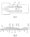
- Figure 7 shows schematically the cam path 48, in a plane.
- Cam 23 is a heart-cam, the cam path 48 has a heart shape.
- the letters A to N indicate different successive positions of a stud 38 on a cam track 48.
- Figure 8 shows schematically the profile of variations altitude of a stud 38, in a cam path 48, as a function of different positions A to N in Figure 7.
- the stud 38 goes from A to B staying at altitude 0.
- the pin 38 then goes from B to C, following a ramp, from altitude 0 to altitude 1, then from C to D, staying at altitude 1.
- the pin 38 can travel the cam path 48, between A and D of reversibly. If the pressure on the gripping button 28, at against the spring 27, is released, the stud 38 returns to A, under the effect of the spring return force 27.
- the transition from D to E is carried out according to a step or a ramp whose slope is strong enough for this portion of the cam path 48, the displacement of the stud 38 is done so irreversible. That is, if the pressure is released on the grip 28, nipple 38 cannot return to B, despite the force supplied by spring 27.
- the stud 38 changes from E to G then to H, according to a unique path since the altitude decreases up to 0.3 in H, and that the slope between G and H is such that the nipple 38 cannot go back.
- the grip button 28 is still pressed into the dashboard 2, the cam 23 comes into abutment against the transverse wall 29, when the stud 38 is in F.
- the nipple 38 returns to E then to H, as described previously.
- the cam 23 is in a stable position in the finger 25 because of a on the one hand, the altitude in H is lower than in G and, on the other hand, the passage 54 has a concave surface capable of retaining the stud 38 when it comes from position E under the effect of the return force of spring 27.
- the nipple 38 is thus ready for a new A-N cycle such as that described above.
- the free end of the stud 38, during the course A-N described above, is constantly in contact with the bottom of the path channel cam 48, thanks to the elasticity of the tongue 34.
- Figure 9a corresponds to the stable position H. If the user lightly press the grip button 28 ( Figure 9b), the nipple 38 changes from H to I or K. When the user then releases the pressure on the gripping button 28, the stud 38 changes from I or K to A. In this position, the gripping button 28 is protruding on the board edge 2 (figure 9c). The plug 6 can then, by pulling on the button grip 28, be extracted from the supply body 4, to connect on the supply body 4 another object such as a charger for mobile phone, or light a cigar or cigarette.
- the user can, if wish to light a cigarette or cigar, operate differently. he press the gripping button 28 but, when the nipple 38 arrives in the K position and that the finger 25 and the cam 23 are in abutment, the user continues to press the gripping button 28 in the dashboard 2 (figures 9e).
- the plug 6 then functions as a classic cigar lighter plug.
- the stud returns to position A, in which the gripping plug 28 is flush with the surface for example dashboard 2; while the cup remains stuck in the bimetallic strip.
- Figures 10a, 10b and 10c schematically illustrate the respective positions of finger 25 and cam 23 when the stud is in positions A and H. It can be clearly seen there that the cam 23 is in abutment against the transverse wall 29, in FIG. 10a.
- the plans of section of Figures 10a and 10b are rotated 90 ° one relative to the other. It can therefore be seen that the finger 25 is held in the stopper of grip 28 but that it turned around the 0-0 axis between the positions corresponding respectively to Figures 10a and 10b.
- the plan section corresponding to Figure 10c is rotated 90 ° around the axis 0-0, compared to that of Figure 10b.
- the cam path 48 is longitudinally limited by two stops.
- One of these stops corresponding to the contact of the cam 23 with the transverse wall 29 ( Figure 10a) and the other corresponding to the contact of the guide ribs 44 at the bottom of the guide grooves 46 (FIG. 10c).
- These stops are such that in the corresponding positions, it is not the nipple 38 itself which limits the relative movements of the finger 25 relative to the cam 23.
- the grip button 28 when it extracts the plug or heater 4 or when the force return spring 27 acts, it does not act on the stud 38, stresses directed parallel to the longitudinal axis 0-0.
- the arrows X and Y indicate respectively the paths of transmission of the forces when the user presses the grip button 28 or the extract of the dashboard 2. These arrows X and Y pass through the stops indicated above.
- the gripping button 28 is provided with clips 26 against draft, serving as an axial stop to the finger 25, the gripping button 28 can be made in two parts: a cap 58 and a ring 60.
- the retaining structure 40 and its groove 42 are replaced by a ring 62 projecting from the outer surface of the finger cylinder 25.
- the cap 58 is formed by a cylinder plugged at one end by a transverse wall 29 similar to that already described.
- the cap 58 has two studs 64 projecting protruding on the outer surface of the cylinder.
- the ring 60 of the cap 58 is formed of a cylinder whose wall is provided with two openings 66.
- the studs 64 and the openings 66 cooperate to form a type of assembly means clip.
- One of the open ends of the ring 60 is narrowed, by so as to retain the finger 25 at the level of the ring 62.
- the cap 58 and ring 60 form a cage in which finger 25 is held captive when the studs 64 are engaged with the openings 66.
- a flange 68 made of plastic, is placed around the grip 28. This collar 68 is intended to collect the radial forces that the user is likely to impose when the gripping button 28 abuts against an outside guide 70, cylindrical, heating plug 6.
- the guide 70 is made of a transparent plastic material or translucent to serve as a light guide.
- the number of cam paths 48 and 38 nipples can be different from two.
Landscapes
- Engineering & Computer Science (AREA)
- Physics & Mathematics (AREA)
- General Physics & Mathematics (AREA)
- Automation & Control Theory (AREA)
- Transportation (AREA)
- Mechanical Engineering (AREA)
- Push-Button Switches (AREA)
- Mechanical Control Devices (AREA)
- Passenger Equipment (AREA)
- Vehicle Step Arrangements And Article Storage (AREA)
- Mechanisms For Operating Contacts (AREA)
- Transmission Devices (AREA)
Applications Claiming Priority (2)
| Application Number | Priority Date | Filing Date | Title |
|---|---|---|---|
| FR9915070A FR2801691B1 (fr) | 1999-11-30 | 1999-11-30 | Dispositif de commande a plusieurs positions stables, notamment pour allume-cigares |
| FR9915070 | 1999-11-30 |
Publications (2)
| Publication Number | Publication Date |
|---|---|
| EP1107087A1 true EP1107087A1 (de) | 2001-06-13 |
| EP1107087B1 EP1107087B1 (de) | 2005-01-19 |
Family
ID=9552713
Family Applications (1)
| Application Number | Title | Priority Date | Filing Date |
|---|---|---|---|
| EP00403313A Expired - Lifetime EP1107087B1 (de) | 1999-11-30 | 2000-11-27 | Steuervorrichtung mit mehreren stabilen Positionen, insbesondere fur Zigarrenanzünder |
Country Status (6)
| Country | Link |
|---|---|
| US (1) | US6414272B2 (de) |
| EP (1) | EP1107087B1 (de) |
| JP (1) | JP2001222930A (de) |
| DE (1) | DE60017536T2 (de) |
| ES (1) | ES2235805T3 (de) |
| FR (1) | FR2801691B1 (de) |
Families Citing this family (5)
| Publication number | Priority date | Publication date | Assignee | Title |
|---|---|---|---|---|
| GB0010238D0 (en) | 2000-04-28 | 2000-06-14 | Northeastern Components Intern | Locking mechanism for chair and pushbutton control therefor |
| DE10306583A1 (de) * | 2003-02-17 | 2004-09-02 | BSH Bosch und Siemens Hausgeräte GmbH | Lagervorrichtung für einen versenkbaren Knebel |
| DE102005004724B4 (de) * | 2005-02-02 | 2006-11-23 | Casco Schoeller Gmbh | Betätigungseinheit für einen Heizeinsatz eines Zigarettenanzünders |
| USD565791S1 (en) * | 2007-04-16 | 2008-04-01 | William Crawford | Combined cigarette lighter sheath and support bracket |
| US7628632B2 (en) * | 2008-04-25 | 2009-12-08 | Casco Products Corporation | Locking mechanism |
Citations (3)
| Publication number | Priority date | Publication date | Assignee | Title |
|---|---|---|---|---|
| DE3642833A1 (de) * | 1985-12-21 | 1987-06-25 | Vaillant Joh Gmbh & Co | Schalter mit einer drucktaste |
| US5223695A (en) * | 1990-07-24 | 1993-06-29 | Schoeller & Co. Elektrotechnische Fabrik Gmbh & Co. | Electric cigarette lighter |
| FR2758111A1 (fr) | 1997-01-06 | 1998-07-10 | Valeo Vision | Allume-cigares a moyens de verrouillage, notamment pour vehicules automobiles |
Family Cites Families (9)
| Publication number | Priority date | Publication date | Assignee | Title |
|---|---|---|---|---|
| JPS406766Y1 (de) * | 1964-04-10 | 1965-03-01 | ||
| DE2535080C2 (de) * | 1975-08-06 | 1977-12-08 | Schoeller & Co, Elektrotechnische Fabrik Gmbh & Co, 6000 Frankfurt | Beleuchtungseinrichtung für Zigarrenanzünder |
| US4713733A (en) * | 1987-03-25 | 1987-12-15 | Casco Products Corporation | Cigar lighter incorporating glow ring |
| DE3908617A1 (de) * | 1989-03-16 | 1990-09-27 | Schoeller & Co Elektrotech | Automatisch montierbarer und beleuchteter elektrischer zigarrenanzuender |
| FR2724610B1 (fr) * | 1994-09-02 | 1996-12-13 | Valeo Vision | Corps d'allumage pour allume-cigares, notamment pour vehicules automobiles |
| KR960700917A (ko) * | 1994-01-12 | 1996-02-24 | 마르 레메이르 | 자동차용 시가 라이터의 점화체(igniting member for a cigarette lighter, particularly in a motor vehicle) |
| US5403996A (en) * | 1994-02-25 | 1995-04-04 | Casco Products Corporation | Connector receptacle construction for electric cigar lighters |
| US5493098A (en) * | 1994-08-11 | 1996-02-20 | Casco Products Corporation | Electric cigar lighter having combined assembler and connector plug at its rear |
| JP3474016B2 (ja) * | 1994-12-28 | 2003-12-08 | ジヤトコ株式会社 | 自動車用制御装置 |
-
1999
- 1999-11-30 FR FR9915070A patent/FR2801691B1/fr not_active Expired - Fee Related
-
2000
- 2000-11-27 EP EP00403313A patent/EP1107087B1/de not_active Expired - Lifetime
- 2000-11-27 ES ES00403313T patent/ES2235805T3/es not_active Expired - Lifetime
- 2000-11-27 DE DE60017536T patent/DE60017536T2/de not_active Expired - Fee Related
- 2000-11-29 US US09/725,527 patent/US6414272B2/en not_active Expired - Fee Related
- 2000-11-30 JP JP2000365243A patent/JP2001222930A/ja active Pending
Patent Citations (4)
| Publication number | Priority date | Publication date | Assignee | Title |
|---|---|---|---|---|
| DE3642833A1 (de) * | 1985-12-21 | 1987-06-25 | Vaillant Joh Gmbh & Co | Schalter mit einer drucktaste |
| US5223695A (en) * | 1990-07-24 | 1993-06-29 | Schoeller & Co. Elektrotechnische Fabrik Gmbh & Co. | Electric cigarette lighter |
| FR2758111A1 (fr) | 1997-01-06 | 1998-07-10 | Valeo Vision | Allume-cigares a moyens de verrouillage, notamment pour vehicules automobiles |
| US5928539A (en) * | 1997-01-06 | 1999-07-27 | Valeo Vision | Cigar lighter with locking means, especially for motor vehicles |
Also Published As
| Publication number | Publication date |
|---|---|
| FR2801691A1 (fr) | 2001-06-01 |
| US6414272B2 (en) | 2002-07-02 |
| JP2001222930A (ja) | 2001-08-17 |
| DE60017536T2 (de) | 2006-01-12 |
| DE60017536D1 (de) | 2005-02-24 |
| FR2801691B1 (fr) | 2005-04-08 |
| EP1107087B1 (de) | 2005-01-19 |
| ES2235805T3 (es) | 2005-07-16 |
| US20010019047A1 (en) | 2001-09-06 |
Similar Documents
| Publication | Publication Date | Title |
|---|---|---|
| EP1036519B1 (de) | Auftragsvorrichtung mit Austragsspindel, die durch eine Zugfeder in ihre Ausgangslage zurück geholt wird | |
| EP0491626A1 (de) | Elektrischer Koaxialverbinder | |
| EP0032091A2 (de) | Behälter für steife Produkte, wie z.B. Stäbchen, Bleistiftminen und dgl. | |
| EP1107087B1 (de) | Steuervorrichtung mit mehreren stabilen Positionen, insbesondere fur Zigarrenanzünder | |
| CH661572A5 (fr) | Actionneur lineaire a systeme vis-ecrou. | |
| EP1106430B1 (de) | Beleuchteter Zigarrenanzünder | |
| EP0814274A2 (de) | Vorrichtung zum Befestigen des Gelenkes eines Druckzylinders auf ein Kupplungspedal von einem Kraftfahrzeug | |
| FR2606330A1 (fr) | Instrument d'ecriture de type retractable | |
| WO2015136202A1 (fr) | Etui spécialement destiné à contenir un bâton tel qu'un raisin de rouge à lèvres et produit comprenant un bâton emballé dans un tel étui. | |
| FR2522394A1 (fr) | Allume-cigares electrique dote d'un interrupteur a bilame conforme en disque a declic | |
| FR2496021A1 (fr) | Allume-cigares electrique pour vehicules automobiles et autres applications analogues | |
| FR2487271A1 (fr) | Allume-cigare electrique, notamment pour vehicules automobiles | |
| EP0098231B1 (de) | Gashahn mit piezoelektrischer Vorrichtung und gasbeheizte Geräte mit einem solchen Gashahn | |
| FR2868017A1 (fr) | Dispositif diffuseur de parfum ou analogue, pour habitacle de vehicule automobile | |
| FR2615321A1 (fr) | Manette pour commutateur electrique | |
| EP3766377B1 (de) | Epilationskopf-rolle für epilationsgerät, epilationskopf und epilationsgerät, die mit einer solchen rolle ausgestattet sind | |
| FR2523691A1 (fr) | Crecelle lumineuse | |
| FR2596540A1 (fr) | Tirette de commande a distance | |
| EP0776785A1 (de) | Entfernbarer Zigarrenanzündereinsatz für Kraftfahrzeuge | |
| FR2753575A1 (fr) | Contacteur tournant a ruban, notamment pour vehicules automobiles | |
| FR2686801A1 (fr) | Baton de ski. | |
| EP0403359B1 (de) | Auslöseteil für einen elektrischen Schalter in Fahrtrichtungsblinkanlagen eines Kraftfahrzeuges | |
| FR2701438A1 (fr) | Bouchon amovible d'allume-cigares, notamment pour véhicules automobiles. | |
| WO2025012550A1 (fr) | Appareil de coiffure multimode de soufflage comprenant un mécanisme de commande à bouton pousser-pousser | |
| EP1109687B1 (de) | Steuereinrichtung für kraftfahrzeugausrüstung |
Legal Events
| Date | Code | Title | Description |
|---|---|---|---|
| PUAI | Public reference made under article 153(3) epc to a published international application that has entered the european phase |
Free format text: ORIGINAL CODE: 0009012 |
|
| AK | Designated contracting states |
Kind code of ref document: A1 Designated state(s): DE ES FR GB IT |
|
| AX | Request for extension of the european patent |
Free format text: AL;LT;LV;MK;RO;SI |
|
| 17P | Request for examination filed |
Effective date: 20011213 |
|
| AKX | Designation fees paid |
Free format text: DE ES FR GB IT |
|
| 17Q | First examination report despatched |
Effective date: 20031216 |
|
| GRAP | Despatch of communication of intention to grant a patent |
Free format text: ORIGINAL CODE: EPIDOSNIGR1 |
|
| GRAS | Grant fee paid |
Free format text: ORIGINAL CODE: EPIDOSNIGR3 |
|
| GRAA | (expected) grant |
Free format text: ORIGINAL CODE: 0009210 |
|
| AK | Designated contracting states |
Kind code of ref document: B1 Designated state(s): DE ES FR GB IT |
|
| REG | Reference to a national code |
Ref country code: GB Ref legal event code: FG4D Free format text: NOT ENGLISH |
|
| REF | Corresponds to: |
Ref document number: 60017536 Country of ref document: DE Date of ref document: 20050224 Kind code of ref document: P |
|
| GBT | Gb: translation of ep patent filed (gb section 77(6)(a)/1977) |
Effective date: 20050307 |
|
| REG | Reference to a national code |
Ref country code: ES Ref legal event code: FG2A Ref document number: 2235805 Country of ref document: ES Kind code of ref document: T3 |
|
| PLBE | No opposition filed within time limit |
Free format text: ORIGINAL CODE: 0009261 |
|
| STAA | Information on the status of an ep patent application or granted ep patent |
Free format text: STATUS: NO OPPOSITION FILED WITHIN TIME LIMIT |
|
| 26N | No opposition filed |
Effective date: 20051020 |
|
| PGFP | Annual fee paid to national office [announced via postgrant information from national office to epo] |
Ref country code: GB Payment date: 20061110 Year of fee payment: 7 |
|
| PGFP | Annual fee paid to national office [announced via postgrant information from national office to epo] |
Ref country code: DE Payment date: 20071108 Year of fee payment: 8 Ref country code: ES Payment date: 20071119 Year of fee payment: 8 |
|
| PGFP | Annual fee paid to national office [announced via postgrant information from national office to epo] |
Ref country code: IT Payment date: 20071116 Year of fee payment: 8 |
|
| GBPC | Gb: european patent ceased through non-payment of renewal fee |
Effective date: 20071127 |
|
| PG25 | Lapsed in a contracting state [announced via postgrant information from national office to epo] |
Ref country code: GB Free format text: LAPSE BECAUSE OF NON-PAYMENT OF DUE FEES Effective date: 20071127 |
|
| PG25 | Lapsed in a contracting state [announced via postgrant information from national office to epo] |
Ref country code: IT Free format text: LAPSE BECAUSE OF NON-PAYMENT OF DUE FEES Effective date: 20081127 |
|
| PG25 | Lapsed in a contracting state [announced via postgrant information from national office to epo] |
Ref country code: DE Free format text: LAPSE BECAUSE OF NON-PAYMENT OF DUE FEES Effective date: 20090603 |
|
| REG | Reference to a national code |
Ref country code: ES Ref legal event code: FD2A Effective date: 20081128 |
|
| PG25 | Lapsed in a contracting state [announced via postgrant information from national office to epo] |
Ref country code: ES Free format text: LAPSE BECAUSE OF NON-PAYMENT OF DUE FEES Effective date: 20081128 |
|
| REG | Reference to a national code |
Ref country code: FR Ref legal event code: PLFP Year of fee payment: 16 |
|
| REG | Reference to a national code |
Ref country code: FR Ref legal event code: PLFP Year of fee payment: 17 |
|
| PGFP | Annual fee paid to national office [announced via postgrant information from national office to epo] |
Ref country code: FR Payment date: 20161130 Year of fee payment: 17 |
|
| REG | Reference to a national code |
Ref country code: FR Ref legal event code: ST Effective date: 20180731 |
|
| PG25 | Lapsed in a contracting state [announced via postgrant information from national office to epo] |
Ref country code: FR Free format text: LAPSE BECAUSE OF NON-PAYMENT OF DUE FEES Effective date: 20171130 |