EP1107172A1 - Kartenlesevorrichtung mit beleuchtetem Einsteckschlitz - Google Patents
Kartenlesevorrichtung mit beleuchtetem Einsteckschlitz Download PDFInfo
- Publication number
- EP1107172A1 EP1107172A1 EP00122657A EP00122657A EP1107172A1 EP 1107172 A1 EP1107172 A1 EP 1107172A1 EP 00122657 A EP00122657 A EP 00122657A EP 00122657 A EP00122657 A EP 00122657A EP 1107172 A1 EP1107172 A1 EP 1107172A1
- Authority
- EP
- European Patent Office
- Prior art keywords
- flap
- slot
- card
- light source
- unit
- Prior art date
- Legal status (The legal status is an assumption and is not a legal conclusion. Google has not performed a legal analysis and makes no representation as to the accuracy of the status listed.)
- Granted
Links
Images
Classifications
-
- G—PHYSICS
- G06—COMPUTING OR CALCULATING; COUNTING
- G06K—GRAPHICAL DATA READING; PRESENTATION OF DATA; RECORD CARRIERS; HANDLING RECORD CARRIERS
- G06K13/00—Conveying record carriers from one station to another, e.g. from stack to punching mechanism
- G06K13/02—Conveying record carriers from one station to another, e.g. from stack to punching mechanism the record carrier having longitudinal dimension comparable with transverse dimension, e.g. punched card
- G06K13/08—Feeding or discharging cards
- G06K13/0868—Feeding or discharging cards using an arrangement for keeping the feeding or insertion slot of the card station clean of dirt, or to avoid feeding of foreign or unwanted objects into the slot
- G06K13/0875—Feeding or discharging cards using an arrangement for keeping the feeding or insertion slot of the card station clean of dirt, or to avoid feeding of foreign or unwanted objects into the slot the arrangement comprising a shutter for blocking at least part of the card insertion slot
-
- G—PHYSICS
- G06—COMPUTING OR CALCULATING; COUNTING
- G06K—GRAPHICAL DATA READING; PRESENTATION OF DATA; RECORD CARRIERS; HANDLING RECORD CARRIERS
- G06K13/00—Conveying record carriers from one station to another, e.g. from stack to punching mechanism
- G06K13/02—Conveying record carriers from one station to another, e.g. from stack to punching mechanism the record carrier having longitudinal dimension comparable with transverse dimension, e.g. punched card
- G06K13/08—Feeding or discharging cards
Definitions
- the invention relates to a card reading device according to the preamble of claim 1.
- a card reading device has become known from DE 197 38 412, at which the device consists of two separate units, namely one from a slot unit on a wall or door of a machine can be fastened and has an insertion slot.
- the reading unit contains a control module, for example in the form of a circuit board for performing all functions when reading a card including locking the card in the contact unit.
- Insert slot with a protective flap that is normally closed and for example by gravity or a spring in the closed position is biased. The protective flap serves to prevent unwanted entry to prevent contamination or the like.
- the protective flap be designed so that only one card in the slot can be inserted while other narrower items, e.g. B. also coins, can not be inserted.
- the invention has for its object to a card reader create, in which the operation is possible even in the dark.
- a printed circuit board arranged, which a plug connection can be connected to the control module.
- On the circuit board at least one light source is arranged, for example a light-emitting one Diode (LED).
- LED light-emitting one Diode
- the LED is arranged on the circuit board belonging to the slot unit, which enables better lighting in a desired location.
- the protective flap is made of one shaped transparent material.
- the invention Flap contains a prismatic section which is aligned with the light source with an entry and an exit surface for the light beam to illuminate the flap such that from the Flap leaking light also enters through the insertion slot.
- the invention Flap is preferably constantly lit, so that a potential A machine user immediately finds the insertion slot without that other lighting is required on the machine or in the area is.
- the valve also serve to introduce others To prevent objects.
- An embodiment of the invention provides for this before that the flap extending parallel to the pivot axis Has transverse slot, the length of which is slightly less than the width a card, the cross slot is designed so that one in the slot imported item that is less than the card has when the flap is initially pivoted in the transverse slot is pinched.
- the cross slot or the cross recess has a slightly larger height than the height of the insertion slot in the slot unit. A slightly lower item, but a lower one Width than a card is therefore picked up by the cross slot, so that the protective flap is initially pivoted somewhat. From one certain pivoting angle, however, the flap is pivoted on another hindered so that it is no longer possible the object insert further into the slot.
- the invention can also be realized with protective flaps, which are not made of transparent material. If, on the other hand, a card is inserted, bumps them against side flap sections on either side of the slot that are not deepened. This results in a normal pivoting of the Flap, and the card can be inserted into the contact unit.
- Another embodiment of the invention provides that parallel in a groove a linear sealing element is added to the swivel axis, which slidably engages the facing side of the card when the Card is inserted into the slot.
- the sealing element carries one wiping movement on the card surface, thereby preventing that moisture on the card to sensitive electronic parts of the reader is brought up.
- the sealing element is preferably annular and received in a circumferential groove of the flap.
- the flap has at least one projecting section on its rear side, which the installation of the flap in the correct position or the pivoting of the The flap is prevented if the flap is inserted in the wrong orientation.
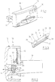
- a slot unit 10 is shown with a housing 12 in which an insertion slot 14 is arranged and the three openings 16 for receiving of key sections of key switches or the like.
- On the rear of the slot unit 10 are two rear-facing approaches provided, one of which is shown at 18 with a lateral recess 20.
- the lugs 18 are used to insert into socket sections a reading unit, not shown, which with the slot unit 10 via a Plug connection is connectable, with a corresponding latching section in the recess 20 engages.
- a connection is, for example described in the aforementioned DE 197 38 412.
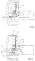
- FIGS. 2 to 5 there is one in the interior of the slot unit 10 Protective flap 22 is pivotally mounted about a longitudinal axis.
- the structure of the Protective flap can be clearly seen in Fig. 3.
- the protective flap 22 has a cylindrical section in the upper region 24, which ends at the ends in cylindrical pins 26, 28 with their Help the flap 22 is pivotally mounted about a pivot axis.
- the Slot unit 10 can have corresponding bearing slots (not shown), in which the pins 26, 28 are received to a corresponding Allow pivotal movement of the flap, as in FIGS. 4 and 5 shown.
- the flap 22 also has prismatic sections 30, 32 their mode of operation in connection with FIGS. 2 to 5 are still discussed becomes.
- Ear-shaped lugs 34, 36 are provided on the rear near the ends, whose task is also explained.
- On the front side has the protective flap 22 below the cylindrical portion 24 slot-like recess 38, which extends almost over the entire length or width of the flap 22 extends.
- the slot 38 is closed at both ends.
- a circumferential groove 40 is provided below the transverse slot 38. she serves to receive a linear circumferential sealing element 42, as shown in Fig. 4.
- the transverse slot 38 has an extent such that it is somewhat less than the width of a map.
- the card edge does not get into the slot 38, but against the lateral end portions of the flap 22 so that the flap is in the open position can be pivoted, as shown in Fig. 4.
- the inserted Card is labeled 44 there.
- the flap 22 arrives after the card 44 has been removed by the action of gravity back into the closed position according to Fig. 2.
- Die The pivot axis, which is defined by the journals 26, 28, is eccentric arranged and allows automatic swiveling back.
- a circuit board 50 is attached, which has a Plug connection, not shown, with the reading unit, not shown, electrically or is electronically connectable.
- the circuit board 50 contains two LEDs, one of which one is shown at 52. The direction of radiation is down, as in Fig. 2 can be seen.
- the LEDs 52 are facing the prismatic sections 30, 32 aligned.
- the light beam enters the facing surface of the prismatic Section 34, 36 and is defined by a deflecting surface 54 of the prismatic Section 30 directed in the direction of transverse slot 38 through the insertion slot 14 through.
- the Protective flap 22 consists of a transparent material and the deflecting surface 54 has mirror effect.
- the protective flap 22 or the insertion slot 14 is illuminated, so that the card can also be used without problems Darkness can be introduced if there is adequate external lighting is not present.
- the flap 22 can theoretically also in an orientation rotated by 180 ° be inserted into the bearing recesses of the slot unit 10. Around to indicate this to the installer or to actuate the flap 22 prevent the ear-shaped portions 34 are provided. You bring that Flap 22 when installed incorrectly in a position that differs from that of FIG. 2 and more similar to that of FIG. 5. This is how the fitter recognizes the wrong one Installation position. Even if this is not noticed, it is one Function of the flap is no longer possible because of the ear-shaped sections 34 prevent pivoting. This will insert a card blocked.
- the sealing element 42 fulfills a wiping function.
- the facing section of the sealing element 42 slides on the facing one Along the surface of the map 44, in which e.g. a chip that is not shown by the Contact unit is read, is embedded. In this way prevents moisture on card 44 from becoming sensitive electronic components.
Landscapes
- Physics & Mathematics (AREA)
- General Physics & Mathematics (AREA)
- Engineering & Computer Science (AREA)
- Theoretical Computer Science (AREA)
- Casings For Electric Apparatus (AREA)
- Optical Communication System (AREA)
- Coupling Device And Connection With Printed Circuit (AREA)
- Facsimile Scanning Arrangements (AREA)
Abstract
Description
- Fig. 1
- zeigt perspektivisch eine Schlitzeinheit einer Kartenlesevorrichtung.
- Fig. 2
- zeigt einen Querschnitt durch die Schlitzeinheit nach Fig. 1 mit einer Schutzklappe.
- Fig. 3
- zeigt perspektivisch die Schutzklappe nach Fig. 2.
- Fig. 4
- zeigt eine ähnliche Darstellung wie Fig. 2 beim Einführen einer Karte.
- Fig. 5
- zeigt eine ähnliche Darstellung wie Fig. 2 oder 4 beim Einführen eines Gegenstandes, der schmaler als eine Karte ist.
Claims (6)
- Kartenlesevorrichtung, die eine Schlitzeinheit und eine Leseeinheit aufweist, die lösbar miteinander verbindbar sind, wobei die Leseeinheit ein elektronisches Steuermodul für die Kartenlesefunktionen und die Schlitzeinheit eine Schutzklappe aufweist, die um eine Achse verschwenkbar gelagert und in die Schließstellung vorgespannt ist, dadurch gekennzeichnet, daß in der Schlitzeinheit (10) eine Leiterplatte (50) angeordnet ist, die über eine Steckverbindung mit dem Steuermodul verbindbar ist und an der mindestens eine Lichtquelle (52) angeordnet ist, die Schutzklappe (22) aus transparentem Material geformt ist und mindestens einen zur Lichtquelle (52) ausgerichteten prismatischen Abschnitt (30) aufweist mit einer Ein- und einer Ausstrahlfläche zur Beleuchtung der Klappe (22) dergestalt, daß aus der Klappe (22) austretendes Licht auch durch den Einsteckschlitz (14) tritt.
- Vorrichtung nach Anspruch 1, dadurch gekennzeichnet, daß die Lichtquelle eine lichtemittierende Diode (LED) ist.
- Vorrichtung nach Anspruch 1 oder 2, dadurch gekennzeichnet, daß die Klappe einen sich parallel zur Schwenkachse erstreckenden Querschlitz (38) aufweist, dessen Länge etwas geringer ist als die Breite einer Karte (44), wobei der Querschlitz (38) so ausgelegt ist, daß ein in den Einsteckschlitz (14) eingesteckter Gegenstand (46), der eine geringere Breitenausdehnung als die Karte (44) aufweist, beim anfänglichen Verschwenken der Klappe (22) im Querschlitz (38) eingeklemmt wird.
- Vorrichtung nach einem der Ansprüche 1 bis 3, dadurch gekennzeichnet, daß in einer Nut (40) parallel zur Schwenkachse ein linienförmiges Dichtungselement (42) aufgenommen ist, das mit der zugekehrten Seite der Karte (44) in gleitendem Eingriff tritt, wenn die Karte (44) in den Einsteckschlitz (14) eingeführt wird.
- Vorrichtung nach Anspruch 4, dadurch gekennzeichnet, daß eine umlaufende Nut (40) vorgesehen ist zur Aufnahme eines ringförmigen Dichtelements (42).
- Vorrichtung nach einem der Ansprüche 1 bis 5, dadurch gekennzeichnet, daß die Klappe (22) an ihrer Rückseite mindestens einen vorspringenden Abschnitt (34, 36) aufweist, der den Einbau der Klappe (22) in die korrekte Lage bzw. ein Verschwenken der Klappe (22) verhindert bzw. ein Einstecken einer Karte blockiert, wenn die Klappe (22) in einer falschen Orientierung eingesetzt wird.
Applications Claiming Priority (2)
| Application Number | Priority Date | Filing Date | Title |
|---|---|---|---|
| DE19959463A DE19959463C2 (de) | 1999-12-10 | 1999-12-10 | Kartenlesevorrichtung |
| DE19959463 | 1999-12-10 |
Publications (2)
| Publication Number | Publication Date |
|---|---|
| EP1107172A1 true EP1107172A1 (de) | 2001-06-13 |
| EP1107172B1 EP1107172B1 (de) | 2007-04-04 |
Family
ID=7932057
Family Applications (1)
| Application Number | Title | Priority Date | Filing Date |
|---|---|---|---|
| EP00122657A Expired - Lifetime EP1107172B1 (de) | 1999-12-10 | 2000-10-18 | Kartenlesevorrichtung mit beleuchtetem Einsteckschlitz |
Country Status (4)
| Country | Link |
|---|---|
| EP (1) | EP1107172B1 (de) |
| AT (1) | ATE358856T1 (de) |
| DE (2) | DE19959463C2 (de) |
| ES (1) | ES2282075T3 (de) |
Cited By (3)
| Publication number | Priority date | Publication date | Assignee | Title |
|---|---|---|---|---|
| FR2837958A1 (fr) * | 2002-03-27 | 2003-10-03 | Amphenol Tuchel Elect | Connecteur pour carte a memoire comportant un volet de protection contre la salete |
| EP1394729A1 (de) * | 2002-08-30 | 2004-03-03 | Omron Corporation | Transaktionsvorrichtung mit einem transparenten Einsteckschlitz |
| WO2008095757A1 (de) * | 2007-02-03 | 2008-08-14 | Wincor Nixdorf International Gmbh | Selbstbedienungsgerät |
Families Citing this family (7)
| Publication number | Priority date | Publication date | Assignee | Title |
|---|---|---|---|---|
| JP4376804B2 (ja) | 2005-02-08 | 2009-12-02 | 三菱電機株式会社 | 記録媒体用開閉機構 |
| DE102005025878B4 (de) * | 2005-06-06 | 2008-01-03 | Audi Ag | Kartenlesevorrichtung |
| DE102006008892B4 (de) * | 2006-02-19 | 2008-04-30 | Gerhard Dipl.-Ing. Richter (FH) | Speicherkartenlesegerät |
| DE102006030658A1 (de) * | 2006-07-03 | 2008-01-10 | Siemens Ag | Datenkarteneinführeinrichtung |
| DE102006031880A1 (de) * | 2006-07-10 | 2008-01-17 | Siemens Ag | Kartenaufnahmevorrichtung |
| DE102007062318B4 (de) * | 2007-12-21 | 2010-02-18 | Amphenol-Tuchel Electronics Gmbh | Schmutz- und Manipulationsgeschützter Kartenleser |
| DE102009054504A1 (de) * | 2009-12-10 | 2011-06-16 | Zf Friedrichshafen Ag | Karten-Terminal und Verfahren zur Herstellung eines solchen |
Citations (3)
| Publication number | Priority date | Publication date | Assignee | Title |
|---|---|---|---|---|
| DE3528558A1 (de) * | 1985-08-08 | 1987-02-19 | Siemens Ag | Kartenleseeinrichtung |
| FR2661528A1 (fr) * | 1990-04-30 | 1991-10-31 | Sagem | Dispositif de securite pour appareil lecteur d'informations. |
| EP0902386A2 (de) * | 1997-09-03 | 1999-03-17 | National Rejectors Inc. GmbH | Kartenlesevorrichtung |
Family Cites Families (3)
| Publication number | Priority date | Publication date | Assignee | Title |
|---|---|---|---|---|
| US3766687A (en) * | 1972-02-16 | 1973-10-23 | Docutel Corp | Apparatus for entry control |
| DE9213283U1 (de) * | 1992-10-02 | 1992-11-26 | Siemens AG, 8000 München | Kartenleser |
| DE19815401C2 (de) * | 1998-04-06 | 2002-01-17 | Bernd Pfeifer | Vorrichtung zur Aufnahme und/oder Rückgabe einer Karte mit einem daran angebrachten Datenträger |
-
1999
- 1999-12-10 DE DE19959463A patent/DE19959463C2/de not_active Expired - Fee Related
-
2000
- 2000-10-18 ES ES00122657T patent/ES2282075T3/es not_active Expired - Lifetime
- 2000-10-18 AT AT00122657T patent/ATE358856T1/de not_active IP Right Cessation
- 2000-10-18 DE DE50014216T patent/DE50014216D1/de not_active Expired - Fee Related
- 2000-10-18 EP EP00122657A patent/EP1107172B1/de not_active Expired - Lifetime
Patent Citations (3)
| Publication number | Priority date | Publication date | Assignee | Title |
|---|---|---|---|---|
| DE3528558A1 (de) * | 1985-08-08 | 1987-02-19 | Siemens Ag | Kartenleseeinrichtung |
| FR2661528A1 (fr) * | 1990-04-30 | 1991-10-31 | Sagem | Dispositif de securite pour appareil lecteur d'informations. |
| EP0902386A2 (de) * | 1997-09-03 | 1999-03-17 | National Rejectors Inc. GmbH | Kartenlesevorrichtung |
Cited By (3)
| Publication number | Priority date | Publication date | Assignee | Title |
|---|---|---|---|---|
| FR2837958A1 (fr) * | 2002-03-27 | 2003-10-03 | Amphenol Tuchel Elect | Connecteur pour carte a memoire comportant un volet de protection contre la salete |
| EP1394729A1 (de) * | 2002-08-30 | 2004-03-03 | Omron Corporation | Transaktionsvorrichtung mit einem transparenten Einsteckschlitz |
| WO2008095757A1 (de) * | 2007-02-03 | 2008-08-14 | Wincor Nixdorf International Gmbh | Selbstbedienungsgerät |
Also Published As
| Publication number | Publication date |
|---|---|
| ATE358856T1 (de) | 2007-04-15 |
| ES2282075T3 (es) | 2007-10-16 |
| EP1107172B1 (de) | 2007-04-04 |
| DE19959463C2 (de) | 2002-05-16 |
| DE19959463A1 (de) | 2001-06-21 |
| DE50014216D1 (de) | 2007-05-16 |
Similar Documents
| Publication | Publication Date | Title |
|---|---|---|
| DE102007007841B4 (de) | Handkreissäge mit Beleuchtungseinheit | |
| DE102019204304A1 (de) | Sicherheitsschalter | |
| EP0186737A2 (de) | Aufnahmeeinheit für eine einen elektronischen Schaltkreis enthaltende Datenkarte | |
| EP1107172B1 (de) | Kartenlesevorrichtung mit beleuchtetem Einsteckschlitz | |
| EP2570239A1 (de) | Werkzeugwechselmagazin für eine motorisch angetriebene Werkzeugmaschine und Werkzeugmaschine | |
| DE69920305T2 (de) | Diebstahlsicherungsmarkierer für Artikel mit stabförmigen Teilen | |
| DE3130797A1 (de) | Schliesssystem mit kodeschluessel fuer mehrere funktionen, insbesondere fuer kraftfahrzeuge | |
| EP0315705B1 (de) | Leiterplattenanschlusselement | |
| DE112014001179T5 (de) | Haltegriff für den Fahrzeuginnenraum | |
| EP3302161B1 (de) | Beleuchtetes gurtschloss für eine sicherheitsgurteinrichtung eines kraftfahrzeuges | |
| EP3309805A1 (de) | Kartenschalter | |
| EP1903165A2 (de) | Fenster- oder Türgriff | |
| EP0902386B1 (de) | Kartenlesevorrichtung | |
| DE3511026C2 (de) | ||
| EP1632921A2 (de) | Manueller Gefahrenmelder | |
| EP2106001A1 (de) | Steckdosenanordnung | |
| DE3113773C2 (de) | ||
| DE20211074U1 (de) | Kofferraumabdeckung | |
| DE19922500B4 (de) | Modulare Schaltervorrichtung, insbesondere für Kraftahrzeuge | |
| DE2741410C2 (de) | Münzeinwurfanordnung | |
| EP0408544B1 (de) | Relais | |
| DE19731380C2 (de) | Sicherheits-Matrix für eine Mehrzahl von Sicherheitslogik-Chipkarten | |
| DE102017127164A1 (de) | Endkappe für eine Beleuchtungsröhre, Beleuchtungsröhre und Verfahren zur Montage einer Beleuchtungsröhre | |
| DE68903151T2 (de) | Bedienungsfeld fuer eine fahrzeugklimaanlage. | |
| DE10326855A1 (de) | Optoelektronische Sensoreinrichtung |
Legal Events
| Date | Code | Title | Description |
|---|---|---|---|
| PUAI | Public reference made under article 153(3) epc to a published international application that has entered the european phase |
Free format text: ORIGINAL CODE: 0009012 |
|
| AK | Designated contracting states |
Kind code of ref document: A1 Designated state(s): AT BE CH CY DE DK ES FI FR GB GR IE IT LI LU MC NL PT SE |
|
| AX | Request for extension of the european patent |
Free format text: AL;LT;LV;MK;RO;SI |
|
| 17P | Request for examination filed |
Effective date: 20011006 |
|
| AKX | Designation fees paid |
Free format text: AT BE CH CY DE DK ES FI FR GB GR IE IT LI LU MC NL PT SE |
|
| GRAP | Despatch of communication of intention to grant a patent |
Free format text: ORIGINAL CODE: EPIDOSNIGR1 |
|
| GRAS | Grant fee paid |
Free format text: ORIGINAL CODE: EPIDOSNIGR3 |
|
| GRAA | (expected) grant |
Free format text: ORIGINAL CODE: 0009210 |
|
| AK | Designated contracting states |
Kind code of ref document: B1 Designated state(s): AT BE CH CY DE DK ES FI FR GB GR IE IT LI LU MC NL PT SE |
|
| PG25 | Lapsed in a contracting state [announced via postgrant information from national office to epo] |
Ref country code: FI Free format text: LAPSE BECAUSE OF FAILURE TO SUBMIT A TRANSLATION OF THE DESCRIPTION OR TO PAY THE FEE WITHIN THE PRESCRIBED TIME-LIMIT Effective date: 20070404 |
|
| REG | Reference to a national code |
Ref country code: GB Ref legal event code: FG4D Free format text: NOT ENGLISH |
|
| REG | Reference to a national code |
Ref country code: CH Ref legal event code: EP |
|
| REF | Corresponds to: |
Ref document number: 50014216 Country of ref document: DE Date of ref document: 20070516 Kind code of ref document: P |
|
| REG | Reference to a national code |
Ref country code: IE Ref legal event code: FG4D Free format text: LANGUAGE OF EP DOCUMENT: GERMAN |
|
| GBT | Gb: translation of ep patent filed (gb section 77(6)(a)/1977) |
Effective date: 20070503 |
|
| PG25 | Lapsed in a contracting state [announced via postgrant information from national office to epo] |
Ref country code: SE Free format text: LAPSE BECAUSE OF FAILURE TO SUBMIT A TRANSLATION OF THE DESCRIPTION OR TO PAY THE FEE WITHIN THE PRESCRIBED TIME-LIMIT Effective date: 20070704 |
|
| PG25 | Lapsed in a contracting state [announced via postgrant information from national office to epo] |
Ref country code: PT Free format text: LAPSE BECAUSE OF FAILURE TO SUBMIT A TRANSLATION OF THE DESCRIPTION OR TO PAY THE FEE WITHIN THE PRESCRIBED TIME-LIMIT Effective date: 20070904 |
|
| PGFP | Annual fee paid to national office [announced via postgrant information from national office to epo] |
Ref country code: ES Payment date: 20070919 Year of fee payment: 8 |
|
| NLV1 | Nl: lapsed or annulled due to failure to fulfill the requirements of art. 29p and 29m of the patents act | ||
| ET | Fr: translation filed | ||
| REG | Reference to a national code |
Ref country code: ES Ref legal event code: FG2A Ref document number: 2282075 Country of ref document: ES Kind code of ref document: T3 |
|
| REG | Reference to a national code |
Ref country code: IE Ref legal event code: FD4D |
|
| PG25 | Lapsed in a contracting state [announced via postgrant information from national office to epo] |
Ref country code: NL Free format text: LAPSE BECAUSE OF FAILURE TO SUBMIT A TRANSLATION OF THE DESCRIPTION OR TO PAY THE FEE WITHIN THE PRESCRIBED TIME-LIMIT Effective date: 20070404 Ref country code: DK Free format text: LAPSE BECAUSE OF FAILURE TO SUBMIT A TRANSLATION OF THE DESCRIPTION OR TO PAY THE FEE WITHIN THE PRESCRIBED TIME-LIMIT Effective date: 20070404 Ref country code: IE Free format text: LAPSE BECAUSE OF FAILURE TO SUBMIT A TRANSLATION OF THE DESCRIPTION OR TO PAY THE FEE WITHIN THE PRESCRIBED TIME-LIMIT Effective date: 20070404 |
|
| PLBE | No opposition filed within time limit |
Free format text: ORIGINAL CODE: 0009261 |
|
| STAA | Information on the status of an ep patent application or granted ep patent |
Free format text: STATUS: NO OPPOSITION FILED WITHIN TIME LIMIT |
|
| PGFP | Annual fee paid to national office [announced via postgrant information from national office to epo] |
Ref country code: IT Payment date: 20071030 Year of fee payment: 8 |
|
| 26N | No opposition filed |
Effective date: 20080107 |
|
| BERE | Be: lapsed |
Owner name: NATIONAL REJECTORS, INC. G.M.B.H. Effective date: 20071031 |
|
| PG25 | Lapsed in a contracting state [announced via postgrant information from national office to epo] |
Ref country code: GR Free format text: LAPSE BECAUSE OF FAILURE TO SUBMIT A TRANSLATION OF THE DESCRIPTION OR TO PAY THE FEE WITHIN THE PRESCRIBED TIME-LIMIT Effective date: 20070705 |
|
| PGFP | Annual fee paid to national office [announced via postgrant information from national office to epo] |
Ref country code: FR Payment date: 20070927 Year of fee payment: 8 |
|
| PG25 | Lapsed in a contracting state [announced via postgrant information from national office to epo] |
Ref country code: MC Free format text: LAPSE BECAUSE OF NON-PAYMENT OF DUE FEES Effective date: 20071031 |
|
| PGFP | Annual fee paid to national office [announced via postgrant information from national office to epo] |
Ref country code: DE Payment date: 20071214 Year of fee payment: 8 |
|
| REG | Reference to a national code |
Ref country code: CH Ref legal event code: PL |
|
| PG25 | Lapsed in a contracting state [announced via postgrant information from national office to epo] |
Ref country code: CH Free format text: LAPSE BECAUSE OF NON-PAYMENT OF DUE FEES Effective date: 20071031 Ref country code: LI Free format text: LAPSE BECAUSE OF NON-PAYMENT OF DUE FEES Effective date: 20071031 |
|
| PG25 | Lapsed in a contracting state [announced via postgrant information from national office to epo] |
Ref country code: BE Free format text: LAPSE BECAUSE OF NON-PAYMENT OF DUE FEES Effective date: 20071031 |
|
| PGFP | Annual fee paid to national office [announced via postgrant information from national office to epo] |
Ref country code: GB Payment date: 20080929 Year of fee payment: 9 |
|
| PG25 | Lapsed in a contracting state [announced via postgrant information from national office to epo] |
Ref country code: AT Free format text: LAPSE BECAUSE OF NON-PAYMENT OF DUE FEES Effective date: 20071018 |
|
| REG | Reference to a national code |
Ref country code: FR Ref legal event code: ST Effective date: 20090630 |
|
| PG25 | Lapsed in a contracting state [announced via postgrant information from national office to epo] |
Ref country code: CY Free format text: LAPSE BECAUSE OF FAILURE TO SUBMIT A TRANSLATION OF THE DESCRIPTION OR TO PAY THE FEE WITHIN THE PRESCRIBED TIME-LIMIT Effective date: 20070404 |
|
| PG25 | Lapsed in a contracting state [announced via postgrant information from national office to epo] |
Ref country code: LU Free format text: LAPSE BECAUSE OF NON-PAYMENT OF DUE FEES Effective date: 20071018 Ref country code: IT Free format text: LAPSE BECAUSE OF NON-PAYMENT OF DUE FEES Effective date: 20081018 Ref country code: DE Free format text: LAPSE BECAUSE OF NON-PAYMENT OF DUE FEES Effective date: 20090501 |
|
| PG25 | Lapsed in a contracting state [announced via postgrant information from national office to epo] |
Ref country code: FR Free format text: LAPSE BECAUSE OF NON-PAYMENT OF DUE FEES Effective date: 20081031 |
|
| REG | Reference to a national code |
Ref country code: ES Ref legal event code: FD2A Effective date: 20081020 |
|
| PG25 | Lapsed in a contracting state [announced via postgrant information from national office to epo] |
Ref country code: ES Free format text: LAPSE BECAUSE OF NON-PAYMENT OF DUE FEES Effective date: 20081020 |
|
| PG25 | Lapsed in a contracting state [announced via postgrant information from national office to epo] |
Ref country code: GB Free format text: LAPSE BECAUSE OF NON-PAYMENT OF DUE FEES Effective date: 20091018 |