EP1107385A2 - Elektrischer und/oder optischer Steckverbinder mit einem Rastarm - Google Patents
Elektrischer und/oder optischer Steckverbinder mit einem Rastarm Download PDFInfo
- Publication number
- EP1107385A2 EP1107385A2 EP00126136A EP00126136A EP1107385A2 EP 1107385 A2 EP1107385 A2 EP 1107385A2 EP 00126136 A EP00126136 A EP 00126136A EP 00126136 A EP00126136 A EP 00126136A EP 1107385 A2 EP1107385 A2 EP 1107385A2
- Authority
- EP
- European Patent Office
- Prior art keywords
- locking
- arm
- electrical
- housing
- connector
- Prior art date
- Legal status (The legal status is an assumption and is not a legal conclusion. Google has not performed a legal analysis and makes no representation as to the accuracy of the status listed.)
- Granted
Links
- 230000003287 optical effect Effects 0.000 title claims abstract description 40
- 230000000295 complement effect Effects 0.000 claims description 13
- 239000013307 optical fiber Substances 0.000 description 3
- 238000003780 insertion Methods 0.000 description 2
- 230000037431 insertion Effects 0.000 description 2
- 238000005452 bending Methods 0.000 description 1
- 230000009286 beneficial effect Effects 0.000 description 1
- 238000011161 development Methods 0.000 description 1
- 230000018109 developmental process Effects 0.000 description 1
- 239000000835 fiber Substances 0.000 description 1
- 238000004519 manufacturing process Methods 0.000 description 1
Images



Classifications
-
- G—PHYSICS
- G02—OPTICS
- G02B—OPTICAL ELEMENTS, SYSTEMS OR APPARATUS
- G02B6/00—Light guides; Structural details of arrangements comprising light guides and other optical elements, e.g. couplings
- G02B6/24—Coupling light guides
- G02B6/36—Mechanical coupling means
- G02B6/38—Mechanical coupling means having fibre to fibre mating means
- G02B6/3807—Dismountable connectors, i.e. comprising plugs
- G02B6/389—Dismountable connectors, i.e. comprising plugs characterised by the method of fastening connecting plugs and sockets, e.g. screw- or nut-lock, snap-in, bayonet type
- G02B6/3893—Push-pull type, e.g. snap-in, push-on
-
- G—PHYSICS
- G02—OPTICS
- G02B—OPTICAL ELEMENTS, SYSTEMS OR APPARATUS
- G02B6/00—Light guides; Structural details of arrangements comprising light guides and other optical elements, e.g. couplings
- G02B6/24—Coupling light guides
- G02B6/36—Mechanical coupling means
- G02B6/38—Mechanical coupling means having fibre to fibre mating means
- G02B6/3807—Dismountable connectors, i.e. comprising plugs
- G02B6/3887—Anchoring optical cables to connector housings, e.g. strain relief features
- G02B6/38875—Protection from bending or twisting
-
- G—PHYSICS
- G02—OPTICS
- G02B—OPTICAL ELEMENTS, SYSTEMS OR APPARATUS
- G02B6/00—Light guides; Structural details of arrangements comprising light guides and other optical elements, e.g. couplings
- G02B6/24—Coupling light guides
- G02B6/36—Mechanical coupling means
- G02B6/38—Mechanical coupling means having fibre to fibre mating means
- G02B6/3807—Dismountable connectors, i.e. comprising plugs
- G02B6/389—Dismountable connectors, i.e. comprising plugs characterised by the method of fastening connecting plugs and sockets, e.g. screw- or nut-lock, snap-in, bayonet type
-
- G—PHYSICS
- G02—OPTICS
- G02B—OPTICAL ELEMENTS, SYSTEMS OR APPARATUS
- G02B6/00—Light guides; Structural details of arrangements comprising light guides and other optical elements, e.g. couplings
- G02B6/24—Coupling light guides
- G02B6/42—Coupling light guides with opto-electronic elements
- G02B6/4201—Packages, e.g. shape, construction, internal or external details
- G02B6/4256—Details of housings
- G02B6/426—Details of housings mounting, engaging or coupling of the package to a board, a frame or a panel
- G02B6/4261—Packages with mounting structures to be pluggable or detachable, e.g. having latches or rails
-
- G—PHYSICS
- G02—OPTICS
- G02B—OPTICAL ELEMENTS, SYSTEMS OR APPARATUS
- G02B6/00—Light guides; Structural details of arrangements comprising light guides and other optical elements, e.g. couplings
- G02B6/24—Coupling light guides
- G02B6/42—Coupling light guides with opto-electronic elements
- G02B6/4201—Packages, e.g. shape, construction, internal or external details
- G02B6/4274—Electrical aspects
- G02B6/4277—Protection against electromagnetic interference [EMI], e.g. shielding means
-
- G—PHYSICS
- G02—OPTICS
- G02B—OPTICAL ELEMENTS, SYSTEMS OR APPARATUS
- G02B6/00—Light guides; Structural details of arrangements comprising light guides and other optical elements, e.g. couplings
- G02B6/24—Coupling light guides
- G02B6/42—Coupling light guides with opto-electronic elements
- G02B6/4201—Packages, e.g. shape, construction, internal or external details
- G02B6/4274—Electrical aspects
- G02B6/4284—Electrical aspects of optical modules with disconnectable electrical connectors
-
- G—PHYSICS
- G02—OPTICS
- G02B—OPTICAL ELEMENTS, SYSTEMS OR APPARATUS
- G02B6/00—Light guides; Structural details of arrangements comprising light guides and other optical elements, e.g. couplings
- G02B6/24—Coupling light guides
- G02B6/42—Coupling light guides with opto-electronic elements
- G02B6/4292—Coupling light guides with opto-electronic elements the light guide being disconnectable from the opto-electronic element, e.g. mutually self aligning arrangements
-
- H—ELECTRICITY
- H01—ELECTRIC ELEMENTS
- H01R—ELECTRICALLY-CONDUCTIVE CONNECTIONS; STRUCTURAL ASSOCIATIONS OF A PLURALITY OF MUTUALLY-INSULATED ELECTRICAL CONNECTING ELEMENTS; COUPLING DEVICES; CURRENT COLLECTORS
- H01R13/00—Details of coupling devices of the kinds covered by groups H01R12/70 or H01R24/00 - H01R33/00
- H01R13/62—Means for facilitating engagement or disengagement of coupling parts or for holding them in engagement
- H01R13/627—Snap or like fastening
- H01R13/6271—Latching means integral with the housing
-
- G—PHYSICS
- G02—OPTICS
- G02B—OPTICAL ELEMENTS, SYSTEMS OR APPARATUS
- G02B6/00—Light guides; Structural details of arrangements comprising light guides and other optical elements, e.g. couplings
- G02B6/24—Coupling light guides
- G02B6/36—Mechanical coupling means
- G02B6/38—Mechanical coupling means having fibre to fibre mating means
- G02B6/3807—Dismountable connectors, i.e. comprising plugs
- G02B6/381—Dismountable connectors, i.e. comprising plugs of the ferrule type, e.g. fibre ends embedded in ferrules, connecting a pair of fibres
- G02B6/3817—Dismountable connectors, i.e. comprising plugs of the ferrule type, e.g. fibre ends embedded in ferrules, connecting a pair of fibres containing optical and electrical conductors
-
- G—PHYSICS
- G02—OPTICS
- G02B—OPTICAL ELEMENTS, SYSTEMS OR APPARATUS
- G02B6/00—Light guides; Structural details of arrangements comprising light guides and other optical elements, e.g. couplings
- G02B6/24—Coupling light guides
- G02B6/42—Coupling light guides with opto-electronic elements
- G02B6/4201—Packages, e.g. shape, construction, internal or external details
- G02B6/4246—Bidirectionally operating package structures
Definitions
- the invention relates to an electrical and / or optical connector with a housing for receiving electrical or optical contacts, at least one Has locking arm.
- Another electrical is from US 4,010,998 Connector with a housing for receiving electrical Contacts and a locking arm shown.
- the locking arm points a longitudinal opening to the corresponding locking lug in it to record.
- the two branches are still on their free end rigidly connected.
- a connector with a housing is specified that to accommodate electrical and / or optical contacts is trained.
- the housing has at least one locking arm on.
- the locking arm is from its free end longitudinally divided into two independently movable Partial arms. Each of the arms has a locking projection.
- both Locking projections can be designed, for example, that it can be locked securely. A such latching can still be a considerable game between the two complementary connectors enable. To compensate for this game, the second movable part arm can be used. To do so for example, the corresponding locking projection an oblique Level on that complementary with the latching opening Connector interacts.
- the two arms can be unlocked at the same time. This will do so achieved that one of the partial arms at its free end has a release button with which the second Part arm is operated to unlock.
- the two arms with the release button are easy to manufacture. This will achieved in that the release button as Crossbar formed at the free end of one arm and protrudes beyond the free end of the second arm.
- the arrangement according to the invention with a longitudinally divided Locking arm can be used for both electrical and optical or hybrid connectors can be used.
- she is not limited to being in one piece Connector is located, but can also, for example be provided on a housing, for example accommodates further modular housings with the contact chambers.
- Figure 1 shows an optical according to the invention Connector arrangement in a perspective Exploded view.
- Figure 2 shows the optical connector assembly of Figure 1 in Perspective side view in the not yet inserted Status.
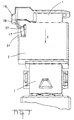
- Figure 3 shows a side view of the optical Plug arrangement according to Figure 1 in the fully inserted Status.
- Figure 4 shows a perspective view of the optical Connector arrangement when not locked.
- Figure 5 shows a plan view of the cable end of the optical connector arrangement.
- Figure 6 shows a perspective view of the optical Plug arrangement in the fully inserted state.
- Figure 7 shows a further perspective side view the optical connector assembly in the fully inserted Status.
- Figure 8 shows a partially sectioned side view of the optical connector arrangement in the fully inserted Condition with a section along the line A according to the figure 5.
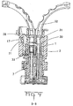
- Figure 9 shows a cross section through the complete inserted optical connector arrangement along the line B according to FIG. 5.
- Figure 1 is an optical connector assembly in Exploded view shown.
- the connector arrangement is there from a first housing 1 of a first connector and a second housing 2 a second complementary Connector.
- the first housing 1 has two Receiving chambers 3, which are used to hold optical contacts serve.
- Sleeves are referred to here as optical contacts, which are applied to fiber optic ends and in the Receiving chambers 3 and 4 can be introduced.
- Figure 1 shows two strain relief sleeves 5 and 6, the can be attached to the optical fibers and serve to that the minimum bending radius is not exceeded.
- the second complementary connector with the housing 2 is connected to an optoelectric module 7 and can be applied to a circuit board. He points Receiving chambers 8 for complementary optical contacts.
- the second housing 2 is designed in the form of a trough to hold the first housing 1.
- On the first housing 1 can be provided on one side coding ribs 9, the in corresponding recesses 10 in the trough-shaped second Housing can be inserted.
- the first housing 1 has a latching arm 11 on one side on.
- the locking arm 11 is to the front end 12 of the Housing 1 connected to the housing. Through a slit 13, the locking arm 11 is divided into two arms 14 and 15.
- the two partial arms 14, 15 each have a free one End open and can be moved independently.
- everyone of the two partial arms 14, 15 has a locking projection 16, 17 on.
- the locking projections 15, 17 are different educated.
- the release button 18 is designed as a crossbar and in its transverse extension chosen such that they over the free end of the second Partial arm 15 protrudes.
- the release button 18 will actuated by pressing it against the housing 1. There they stretch across the free end of the second arm part 15 extends by actuation the release button 18 not only the first arm 14, but also the second arm 15 actuated.
- the second housing 2 has two on one side Locking openings 20 and 21. These locking openings are for Inclusion of the locking projections 16, 17 of the two partial arms 14, 15 of the latch arm 11 of the first housing 1 is formed.
- the two locking openings 20, 21 are each at the corner areas arranged a side wall. This allows you to use the arranged laterally on the partial arms 14, 15 Interacting locking projections 16, 17.
- the optical connector assembly is still not fully inserted state shown.
- the first housing 1 is not yet accordingly equipped with optical contacts.
- the trough-shaped area of the housing 2 are the two locking openings 20 and 21.
- the trough-shaped area is the optical module 7. This has contacts 22, ground contacts 23 one Shielding plate 24, positioning aids 25 and others Contacts 26 for mounting on a circuit board.
- the locking projection 16, which is on the first arm 14 with the Release button 18 is in his Longitudinal expansion in the longitudinal direction of the partial arm 14 smaller than the locking projection 17. This will ensures that the partial arm 14 is securely in the opening 20 locked.
- the opening 20 is of such a size that the Has locking projection 16 game in the locking opening 20. A secure locking of the two connector housings 1 and 2, however with a relatively large game is guaranteed if the Locking projection 16 is locked in the locking opening 20.
- the larger locking projection 17 has on its cable side End a curvature or curvature 27.
- the Locking opening 21 is a wall 28 inclined to the insertion direction S. on that with the curvature 27 of the second locking projection 17th of the second arm 15 cooperates. If the first Locking projection 16 already locked in the locking opening 20 the second locking arm 15 with the locking projection 17 to reduce the play between the two housings 1 and 2. This is achieved in that the locking projection 17 with the curvature 27 at the cable end with sloping plane 28 cooperates with the locking opening 21. Due to the spring forces of the locking arm 15, the one Force in the direction of insertion due to due to appropriate slopes, the game is minimized.
- FIGs 6 and 7 is a side view the latched first partial arm 14 or a side view shown with the latched arm 15. Because of the split locking arm 11 is an independent locking of the two arms possible. The two arms also serve as an energy store, which enables a safe plugging in and Prevents half-sticking. This is because of the special Forming the collar 29 of the second housing 2 enables.
- Figure 8 shows a partial section through the complete inserted connector, the section through the Locking projection 16 is placed, as in Figure 5 by the Section line A-A shown.
- the locking projection 16 locked in the locking opening 20.
- the first housing 1 there is also a chamber housing 30 in which again the optical contacts 31 in the form of sleeves the optical wires 32 can be introduced.
- the first connector is there from the first housing 1, which is designed as a housing is the chamber housing 30 with the optical contacts 31, through a contact fuse 33 in the chamber housing 30 are held and into which the optical fibers are introduced are.
Landscapes
- Physics & Mathematics (AREA)
- General Physics & Mathematics (AREA)
- Optics & Photonics (AREA)
- Engineering & Computer Science (AREA)
- Microelectronics & Electronic Packaging (AREA)
- Electromagnetism (AREA)
- Mechanical Coupling Of Light Guides (AREA)
- Details Of Connecting Devices For Male And Female Coupling (AREA)
Abstract
Description
Claims (9)
- Elektrischer und/oder optischer Steckverbinder mit einem Gehäuse (1) zur Aufnahme elektrischer oder optischer Kontake, das zumindest einen Rastarm (11) aufweist, dadurch gekennzeichnet, dass der Rastarm (11) längsgeteilt ist in zwei unabhängig voneinander bewegliche Teilarme (14,15 )und dass jeder der Teilarme (14,15) einen Rastvorsprung (16,17) aufweist, die unterschiedlich ausgebildet sind.
- Elektrischer und/oder optischer Steckverbinder nach Anspruch 1, dadurch gekennzeichnet, dass einer der Teilarme (14) an seinem freien Ende eine Entriegelungstaste (18) aufweist, durch deren Betätigung auch der zweite Teilarm (15) entriegelt wird.
- Elektrischer und/oder optischer Steckverbinder nach Anspruch 2, dadurch gekennzeichnet, dass die Entriegelungstaste (18) als Querbalken ausgebildet ist und bei Betätigung am freien Ende des zweiten Teilarms (15) angreift.
- Elektrischer und/oder optischer Steckverbinder nach Anspruch 1, dadurch gekennzeichnet, dass die Rastvorsprünge (16,17) der beiden Teilarme (14,15) gegeneinander versetzt angeordnet sind.
- Elektrischer und/oder optischer Steckverbinder nach Anspruch 1, dadurch gekennzeichnet, dass der Rastvorsprung (16) am ersten Teilarm (14) derart ausgebildet ist, dass er eine sichere Verrastung ermöglicht.
- Elektrischer und/oder optischer Steckverbinder nach Anspruch 1, dadurch gekennzeichnet, dass der Rastvorsprung (17) am zweiten Teilarm (15) eine schräge Ebene (27) aufweist, derart, dass er eine Reduzierung des Spiels im verrasteten Zustand ermöglicht.
- Elektrischer und/oder optischer Steckverbinder nach Anspruch 1, dadurch gekennzeichnet, dass der erste Teilarm (14) an seinem freien Ende eine Entriegelungstaste (18) aufweist, durch deren Betätigung auch der zweite Teilarm (15) entriegelt wird und, dass der Rastvorsprung (16) am ersten Teilarm (14) derart ausgebildet ist, dass er eine sichere Verrastung ermöglicht.
- Elektrischer und/oder optischer Steckverbinder nach Anspruch 1, dadurch gekennzeichnet, dass das Gehäuse ein Umgehäuse ist, und dass ein weiteres Gehäuse mit den Kontaktkammern in das Umgehäuse cinbringbar ist.
- Elektrische und/oder optische Steckeranordnung bestehend aus einem ersten Steckverbinder nach einem der Ansprüche 1-7 und einem zweiten komplementären Steckverbinder mit einem Gehäuse (2) zur Aufnahme komplementärer elektrischer oder optischer Kontakte, das zumindest eine Rastöffnung (20,21) zur Verrastung der Rastvorsprünge (16,17) aufweist.
Priority Applications (1)
| Application Number | Priority Date | Filing Date | Title |
|---|---|---|---|
| EP00126136A EP1107385B1 (de) | 1999-11-30 | 2000-11-30 | Elektrischer und/oder optischer Steckverbinder mit einem Rastarm |
Applications Claiming Priority (3)
| Application Number | Priority Date | Filing Date | Title |
|---|---|---|---|
| EP99123724 | 1999-11-30 | ||
| EP99123724 | 1999-11-30 | ||
| EP00126136A EP1107385B1 (de) | 1999-11-30 | 2000-11-30 | Elektrischer und/oder optischer Steckverbinder mit einem Rastarm |
Publications (3)
| Publication Number | Publication Date |
|---|---|
| EP1107385A2 true EP1107385A2 (de) | 2001-06-13 |
| EP1107385A3 EP1107385A3 (de) | 2004-12-01 |
| EP1107385B1 EP1107385B1 (de) | 2011-11-09 |
Family
ID=26071625
Family Applications (1)
| Application Number | Title | Priority Date | Filing Date |
|---|---|---|---|
| EP00126136A Expired - Lifetime EP1107385B1 (de) | 1999-11-30 | 2000-11-30 | Elektrischer und/oder optischer Steckverbinder mit einem Rastarm |
Country Status (1)
| Country | Link |
|---|---|
| EP (1) | EP1107385B1 (de) |
Cited By (1)
| Publication number | Priority date | Publication date | Assignee | Title |
|---|---|---|---|---|
| EP1936754A3 (de) * | 2006-12-21 | 2010-01-06 | Tyco Electronics AMP GmbH | Steckverbinder mit einem Gehäuse mit einem Betätigungselement und einem Rastmittel |
Family Cites Families (3)
| Publication number | Priority date | Publication date | Assignee | Title |
|---|---|---|---|---|
| DE8410243U1 (de) * | 1984-04-03 | 1984-06-28 | C.A. Weidmüller GmbH & Co, 4930 Detmold | Anordnung zur Befestigung elektronischer Bauelemente auf Leiterplatten |
| GB2195501A (en) * | 1986-09-25 | 1988-04-07 | Electronic Components Ltd | Electrical connector |
| FR2669897B1 (fr) * | 1990-11-30 | 1993-01-22 | Labinal | Dispositif de verrouillage de deux elements de boitier l'un par rapport a l'autre. |
-
2000
- 2000-11-30 EP EP00126136A patent/EP1107385B1/de not_active Expired - Lifetime
Non-Patent Citations (1)
| Title |
|---|
| None |
Cited By (1)
| Publication number | Priority date | Publication date | Assignee | Title |
|---|---|---|---|---|
| EP1936754A3 (de) * | 2006-12-21 | 2010-01-06 | Tyco Electronics AMP GmbH | Steckverbinder mit einem Gehäuse mit einem Betätigungselement und einem Rastmittel |
Also Published As
| Publication number | Publication date |
|---|---|
| EP1107385B1 (de) | 2011-11-09 |
| EP1107385A3 (de) | 2004-12-01 |
Similar Documents
| Publication | Publication Date | Title |
|---|---|---|
| EP1509797B1 (de) | Optische steckverbindung | |
| DE19614978A1 (de) | Verbinder mit schwenkbarem Kopplungshebel | |
| DE19654294C2 (de) | Steckerbindungssystem zur Verhinderung einer unvollständigen Verbindung | |
| DE602005003245T2 (de) | Steckverbinder mit Verriegelungsanordnung | |
| DE4234976C2 (de) | Elektrischer Steckverbinder mit Verriegelungsklappe | |
| EP1176670B1 (de) | Elektrischer Steckverbinder sowie Gehäuse für einen solchen elektrischen Steckverbinder | |
| DE19530334B4 (de) | Steckeranordnung mit einem Betätigungsschieber | |
| DE10334589B4 (de) | Steckverbinder | |
| DE19537886B4 (de) | Elektrischer Stecker mit einem Betätigungsschieber | |
| DE4105470C2 (de) | Elektrischer Steckverbinder | |
| EP3403298B1 (de) | Steckverbinder | |
| DE60006331T3 (de) | Steckvorrichtungssystem zur Verhinderung einer falschen Kupplung | |
| DE202004000419U1 (de) | Schraubenlose Leiteranschlussklemme | |
| DE202020104347U1 (de) | Elektrische Kupplung, insbesondere elektrische Steckdose, die mit einer komplementär ausgebildeten elektrischen Kupplung koppelbar ist | |
| DE102020001995A1 (de) | Steckverbinderbaugruppe, Stecksystem und Verfahren | |
| DE10227591B3 (de) | Verbinderanordnung | |
| EP1107385A2 (de) | Elektrischer und/oder optischer Steckverbinder mit einem Rastarm | |
| DE4410950A1 (de) | Elektrischer Verbinder mit Primär- und Sekundärverriegelung der Kontaktelemente | |
| DE19736420B4 (de) | Elektrischer Verbinder, Verbindergehäuse und Verfahren zum Einbringen eines elektrischen Kontaktes in ein Verbindergehäuse | |
| DE19717983B4 (de) | System zur Verriegelung und Entriegelung von Gegenständen von einer vom eigentlichen Verriegelungsort abgelegenen Stelle aus | |
| DE19802554A1 (de) | Steckeranorndung mit einem Betätigungsschieber | |
| DE102021107646A1 (de) | Steckverbinder mit aufsteckbarem Verriegelungselement | |
| DE69635597T2 (de) | Verbinder mit Kontaktverriegelung | |
| DE102021119480B3 (de) | Elektrischer Steckverbinder und Elektrisches Steckverbindersystem | |
| DE19530505B4 (de) | Elektrischer Stecker mit einem Aufnahmegehäuse und einem Kammerblock |
Legal Events
| Date | Code | Title | Description |
|---|---|---|---|
| PUAI | Public reference made under article 153(3) epc to a published international application that has entered the european phase |
Free format text: ORIGINAL CODE: 0009012 |
|
| AK | Designated contracting states |
Kind code of ref document: A2 Designated state(s): AT BE CH CY DE DK ES FI FR GB GR IE IT LI LU MC NL PT SE TR |
|
| AX | Request for extension of the european patent |
Free format text: AL;LT;LV;MK;RO;SI |
|
| PUAL | Search report despatched |
Free format text: ORIGINAL CODE: 0009013 |
|
| AK | Designated contracting states |
Kind code of ref document: A3 Designated state(s): AT BE CH CY DE DK ES FI FR GB GR IE IT LI LU MC NL PT SE TR |
|
| AX | Request for extension of the european patent |
Extension state: AL LT LV MK RO SI |
|
| 17P | Request for examination filed |
Effective date: 20050429 |
|
| AKX | Designation fees paid |
Designated state(s): DE FR GB IT |
|
| 17Q | First examination report despatched |
Effective date: 20080320 |
|
| GRAP | Despatch of communication of intention to grant a patent |
Free format text: ORIGINAL CODE: EPIDOSNIGR1 |
|
| GRAS | Grant fee paid |
Free format text: ORIGINAL CODE: EPIDOSNIGR3 |
|
| GRAA | (expected) grant |
Free format text: ORIGINAL CODE: 0009210 |
|
| AK | Designated contracting states |
Kind code of ref document: B1 Designated state(s): DE FR GB IT |
|
| REG | Reference to a national code |
Ref country code: GB Ref legal event code: FG4D Free format text: NOT ENGLISH |
|
| REG | Reference to a national code |
Ref country code: DE Ref legal event code: R081 Ref document number: 50016186 Country of ref document: DE Owner name: TE CONNECTIVITY GERMANY GMBH, DE Free format text: FORMER OWNER: TYCO ELECTRONICS AMP GMBH, 64625 BENSHEIM, DE |
|
| REG | Reference to a national code |
Ref country code: DE Ref legal event code: R096 Ref document number: 50016186 Country of ref document: DE Effective date: 20120119 |
|
| PG25 | Lapsed in a contracting state [announced via postgrant information from national office to epo] |
Ref country code: IT Free format text: LAPSE BECAUSE OF FAILURE TO SUBMIT A TRANSLATION OF THE DESCRIPTION OR TO PAY THE FEE WITHIN THE PRESCRIBED TIME-LIMIT Effective date: 20111109 |
|
| PLBE | No opposition filed within time limit |
Free format text: ORIGINAL CODE: 0009261 |
|
| STAA | Information on the status of an ep patent application or granted ep patent |
Free format text: STATUS: NO OPPOSITION FILED WITHIN TIME LIMIT |
|
| REG | Reference to a national code |
Ref country code: FR Ref legal event code: ST Effective date: 20120817 |
|
| 26N | No opposition filed |
Effective date: 20120810 |
|
| GBPC | Gb: european patent ceased through non-payment of renewal fee |
Effective date: 20120209 |
|
| REG | Reference to a national code |
Ref country code: DE Ref legal event code: R097 Ref document number: 50016186 Country of ref document: DE Effective date: 20120810 |
|
| PG25 | Lapsed in a contracting state [announced via postgrant information from national office to epo] |
Ref country code: GB Free format text: LAPSE BECAUSE OF NON-PAYMENT OF DUE FEES Effective date: 20120209 |
|
| PG25 | Lapsed in a contracting state [announced via postgrant information from national office to epo] |
Ref country code: FR Free format text: LAPSE BECAUSE OF NON-PAYMENT OF DUE FEES Effective date: 20120109 |
|
| REG | Reference to a national code |
Ref country code: DE Ref legal event code: R082 Ref document number: 50016186 Country of ref document: DE Representative=s name: WILHELM & BECK, DE Ref country code: DE Ref legal event code: R081 Ref document number: 50016186 Country of ref document: DE Owner name: TE CONNECTIVITY GERMANY GMBH, DE Free format text: FORMER OWNER: TYCO ELECTRONICS AMP GMBH, 64625 BENSHEIM, DE |
|
| PGFP | Annual fee paid to national office [announced via postgrant information from national office to epo] |
Ref country code: DE Payment date: 20191119 Year of fee payment: 20 |
|
| REG | Reference to a national code |
Ref country code: DE Ref legal event code: R071 Ref document number: 50016186 Country of ref document: DE |