EP1107395A2 - Lampenfassung - Google Patents
Lampenfassung Download PDFInfo
- Publication number
- EP1107395A2 EP1107395A2 EP00125664A EP00125664A EP1107395A2 EP 1107395 A2 EP1107395 A2 EP 1107395A2 EP 00125664 A EP00125664 A EP 00125664A EP 00125664 A EP00125664 A EP 00125664A EP 1107395 A2 EP1107395 A2 EP 1107395A2
- Authority
- EP
- European Patent Office
- Prior art keywords
- leg
- socket
- abutment
- detent spring
- abutment leg
- Prior art date
- Legal status (The legal status is an assumption and is not a legal conclusion. Google has not performed a legal analysis and makes no representation as to the accuracy of the status listed.)
- Granted
Links
- 239000002184 metal Substances 0.000 claims abstract description 14
- 239000011810 insulating material Substances 0.000 claims abstract description 3
- 229910052736 halogen Inorganic materials 0.000 claims abstract 2
- 150000002367 halogens Chemical class 0.000 claims abstract 2
- 238000003780 insertion Methods 0.000 claims description 5
- 230000037431 insertion Effects 0.000 claims description 5
- 230000007704 transition Effects 0.000 claims description 5
- 230000001154 acute effect Effects 0.000 claims 1
- 239000000463 material Substances 0.000 abstract description 3
- 238000005452 bending Methods 0.000 description 1
- 239000007795 chemical reaction product Substances 0.000 description 1
- 230000013011 mating Effects 0.000 description 1
Images


Classifications
-
- H—ELECTRICITY
- H01—ELECTRIC ELEMENTS
- H01R—ELECTRICALLY-CONDUCTIVE CONNECTIONS; STRUCTURAL ASSOCIATIONS OF A PLURALITY OF MUTUALLY-INSULATED ELECTRICAL CONNECTING ELEMENTS; COUPLING DEVICES; CURRENT COLLECTORS
- H01R33/00—Coupling devices specially adapted for supporting apparatus and having one part acting as a holder providing support and electrical connection via a counterpart which is structurally associated with the apparatus, e.g. lamp holders; Separate parts thereof
- H01R33/05—Two-pole devices
- H01R33/06—Two-pole devices with two current-carrying pins, blades or analogous contacts, having their axes parallel to each other
- H01R33/08—Two-pole devices with two current-carrying pins, blades or analogous contacts, having their axes parallel to each other for supporting tubular fluorescent lamp
- H01R33/0836—Two-pole devices with two current-carrying pins, blades or analogous contacts, having their axes parallel to each other for supporting tubular fluorescent lamp characterised by the lamp holding means
Definitions
- the invention relates to a socket for lamps according to the Preamble of claim 1.
- the The present invention is based on the holding leg of the Latching spring following one in the depth of the socket bend of about 180 ° to be accommodated on the abutment legs, from which the tongue is cut out as a U-shaped tongue is formed.
- the detent spring is in the lamp insertion direction with its U-shaped Bend ahead in a pocket-like recess in the Socket housing inserted until it hits a stop. In This position can be shown on the outside of the abutment leg Locking tongue behind a retaining surface of the socket housing snap, so that the detent spring against a tensile force on the lamp holds securely in the socket housing.
- the free end of the abutment section is supported in this final assembly position by an inward facing one Area within the socket housing.
- the bent shoulder of the holding leg protrudes into the Path of movement of the lamp base or to attack the shoulder mating surface provided on it.
- the present invention has for its object, means and Show ways like a version with at least one Latching spring in the sense of a significant reduction in the material requirement is still to be optimized for the detent spring.
- the invention solves this problem with the features of Claim 1 and is particularly characterized in that the Abutment leg formed from the holding leg and itself is also a latch.
- the essential essence of the invention is therefore that additional, i.e. provided in the extension of the holding leg, To completely leave out abutment legs. According to the invention this happens because the abutment leg and its function from the extended and bent end portion of the detent spring in the area that was previously only relocated from the holding leg was taken. This will result in enormous material savings achieved because - assuming comparable dimensions of the end product - over a third of the length of the metal strip from which the detent spring is produced, is no longer needed.
- the Abutment leg cut out of the flat sheet metal strip and is issued in such a way that its free end corresponds to the end of the Holding leg points on which the bent shoulder is located.
- the arrangement in the prior art is as follows hit that in an end region of the flat holding leg a leg was also cut out in a U shape. However, this was not the abutment leg itself, but one that is detached from it and exhibited special latch. Their free end points to immediately adjacent free end of the metal strip, but not to the free end of the not yet deformed holding leg, which is in the opposite Direction lies.
- the success of the invention is also based on the knowledge that the U-shaped incision in particular Sheet metal strip from which the detent spring is to be made, in a different way than to be ordered so far.
- the abutment leg preferably forms an oblique shape the straight section uplifting transition section into a extending substantially along the straight section End section merges.
- This end section serves to deal with its To support the outer surface on an inner surface of the socket housing, whereas its marginal edge delimits the inner surface Grips behind the lead.
- the abutment leg, starting from the zone of its Connection to the holding leg is essentially straight, that is, without Let the transition section run.
- the invention provides that one over the Connection zone of the transition section on the straight section of the Abutment leg protruding insertion section into one Receiving slot of the socket housing engages.
- the invention is most easily understood on the basis of the in 9 to 12 shown prior art.
- FIG. 9 10 denotes a lamp socket overall, whose socket housing 11 made of insulating material to each other diametrically opposite sides towards the lamp, not shown has open pockets 12 for a detent spring 13 each.
- Each Latch spring 13 is divided into a holding leg 14 and one a bend designated 15, about 180 ° subsequent abutment leg 16.
- This abutment leg 16 is supported with an outer surface 16a near its free end 16b from an inner surface 11a of the socket housing 11.
- a U-shaped incision 17 Fig. 12
- a barb and tongue-like latch 18 18
- the holding leg 14 of the detent spring 13 each has one bent shoulder 21 to attack an appropriate Counter surface of the base 25, not shown in FIGS. 9 to 12 Lamp serves.
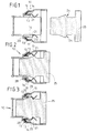
- the holding leg 14 can, for example, be located at 15 Bend the bending axis in the direction of arrow 22 resiliently if a Lamp base 25 (Fig. 1 to 3) is inserted into the lamp holder 10. In the final operating position, the shoulders 21 snap towards one another Arrow direction 22 back into the lamp base 25 holding Operating position.
- the detent spring 13 after the State of the art has several functional elements, namely that for resilient latching attack on the lamp base 25 specific holding leg 14 with shoulder 21, one that is supported on the inside in the socket Abutment leg 16, namely following one end of the holding leg 14 attached U-shaped bend 15 and finally as a further and last functional element the tongue-like from the Abutment leg 16 notched latch 18.
- a detent spring 13 of this known type is a flat sheet metal strip 23 of length L (Fig. 12). It should be emphasized that the free edge 18a of the latch 18 from the free end 23a of the blank 23 points away, the free end 14a of the finished detent spring 13 Holding leg 14 forms. Rather, the edge 18a faces directly adjacent cutting edge 23b, which in the finished detent spring 13 free end of the abutment leg 16 forms.
- the version 10 shown in FIGS. 1 to 3 corresponding to the The invention has detent springs 13, the holding legs 14 of which are in turn one bent shoulder 21 for attacking counter surfaces 24 a Provide lamp base 25.
- the peculiarity is that the abutment leg 16 is integrated in the holding leg 14 and itself is also a latch.
- the tongue 26 is deformed such that a transition section 27 protrudes obliquely from the rectilinear portion of the retaining spring 14 and a free end portion by means of abutment legs 16 essentially to the free end 14a of the holding leg 14 or along this is turned continuously.
- This configuration is particularly from the 4 to 7 can be seen very clearly.
- socket housing 11 In the socket housing 11 are slit-like to the lamp base 25 open slot receptacles 28 are provided, in which the end portions 14b the holding leg 14 are inserted with their end face first. Not groove-like guides are shown in the socket housing 11 for guidance and holding lateral edge regions 14c of the holding legs 14.
Landscapes
- Fastening Of Light Sources Or Lamp Holders (AREA)
- Non-Portable Lighting Devices Or Systems Thereof (AREA)
- Vessels And Coating Films For Discharge Lamps (AREA)
Abstract
Description
- Fig. 1
- einen Längsschnitt durch eine Lampenfassung mit davor schematisch dargestelltem Sockel einer nicht gezeigten Lampe vor dem Einstecken des Sockels in die Fassung,
- Fig. 2
- eine der Fig. 1 entsprechende Darstellung während des Einsteckens des Lampensockels in die Fassung,
- Fig. 3
- eine den Fig. 1 und 2 entsprechende Darstellung mit in Betriebsposition eingestecktem und in der Fassung festgehaltenem Lampensockel,
- Fig. 4
- eine gegenüber den Fig. 1 bis 3 vergrößert dargestellte Seitenansicht der Rastfeder,
- Fig. 5
- eine Stirnansicht der Rastfeder entsprechend dem Ansichtspfeil V in Fig. 4,
- Fig. 6
- eine Seitenansicht der Rastfeder nach Fig. 5 entsprechend dem Ansichtspfeil VI in Fig. 4,
- Fig. 7
- eine perspektivische Ansicht der Rastfeder entsprechend den Fig. 4 bis 6,
- Fig. 8
- eine Aufsicht auf den zur Herstellung der Rastfeder benötigten Blechstreifen nach dem Einschneiden des Bereichs für den Widerlagerschenkel, jedoch vor der Verformung,
- Fig. 9
- eine Fig. 1 entsprechende Schnittdarstellung einer herkömmlichen Lampenfassung,
- Fig. 10
- eine Fig. 4 entsprechende Seitenansicht der bekannten Rastfeder,
- Fig. 11
- eine Fig. 7 entsprechende perspektivische Ansicht der bekannten Rastfeder und
- Fig. 12
- eine maßstabsgetreu wiedergegebene Aufsicht entsprechend Fig. 8 auf einen Blechzuschnitt zur Herstellung der vorbekannten Rastfeder.
Claims (7)
- Fassung (10) für Lampen, insbesondere für Kompakt-Leuchtstofflampen mit Sockeln (25) der Typen G23, G24 oder 2G11 sowie für Halogenlampen mit Sockeln (25) der Typen G12 oder PG12, mit einem Fassungsgehäuse (11) aus Isolierstoff, welches elektrische Anschlußkontakte und mindestens eine Rastfeder (13) zur mechanischen Halterung der in die Fassung (10) eingesteckten Lampe aufweist, wobei die aus einem ebenen Blechstreifen (23) geformte Rastfeder (13) einen mit einer ausgebogenen Schulter (21) am Lampensockel (25) angreifenden federnden Halteschenkel (14), einen sich dem gegenüber im Fassungskörper (11) abstützenden Widerlagerschenkel (16) sowie eine widerhakenartige Rastnase aufweist, die die Rastfeder (13) entgegen einer von Seiten der Lampe ausgeübten Zugkraft unverlierbar im Fassungsgehäuse (11) festhält, dadurch gekennzeichnet, dass der Widerlagerschenkel (16) aus dem Halteschenkel (14) ausgeformt und selbst zugleich auch Rastnase ist.
- Fassung nach Anspruch 1, dadurch gekennzeichnet, dass der Widerlagerschenkel (16) aus dem ebenen Blechstreifen (23) freigeschnitten und derart ausgestellt ist, dass sein freies Ende (16b) zu dem Ende des Halteschenkels (14) weist, an dem sich die ausgebogene Schulter (21) befindet.
- Fassung nach Anspruch 1 oder 2, dadurch gekennzeichnet, dass die Rastfeder (13) einen im wesentlichen geraden Abschnitt aufweist, aus dem der Widerlagerschenkel (16) ausgeschnitten ist und an den sich zum einen Ende hin die ausgebogene Schulter (21) anschließt.
- Fassung nach Anspruch 2 oder 3, dadurch gekennzeichnet, dass der Widerlagerschenkel (16) sich im wesentlichen geradlinig sowie unter einem spitzen Winkel schräg zum geraden Abschnitt des Halteschenkels (14) erstreckt.
- Fassung nach Anspruch 2 oder 3, dadurch gekennzeichnet, dass der Widerlagerschenkel (16) einen sich schräg aus dem geraden Abschnitt erhebenden Übergangsabschnitt (27) ausbildet, der in einen sich zum geraden Abschnitt in der Montagelage im wesentlichen parallel erstreckenden Endabschnitt übergeht.
- Fassung nach Anspruch 5, dadurch gekennzeichnet, dass der Endabschnitt des Widerlagerschenkels (16) mit seiner Außenfläche (16a) an einer Innenfläche des Fassungsgehäuses (11) abgestützt ist und seine Randkante (16b) einen die Innenfläche begrenzenden Vorsprung (29) hintergreift.
- Fassung nach einem der vorhergehenden Ansprüche, dadurch gekennzeichnet, dass ein über die Anbindungszone (26a) des Übergangsabschnitts (27) am geraden Abschnitt des Widerlagerschenkels (16) hinausragender Einsteckabschnitt (14b) in einen Aufnahmeschlitz (28) des Fassungsgehäuses (11) eingreift.
Applications Claiming Priority (2)
| Application Number | Priority Date | Filing Date | Title |
|---|---|---|---|
| DE19958841 | 1999-12-07 | ||
| DE19958841A DE19958841A1 (de) | 1999-12-07 | 1999-12-07 | Lampenfassung |
Publications (3)
| Publication Number | Publication Date |
|---|---|
| EP1107395A2 true EP1107395A2 (de) | 2001-06-13 |
| EP1107395A3 EP1107395A3 (de) | 2002-05-15 |
| EP1107395B1 EP1107395B1 (de) | 2003-07-23 |
Family
ID=7931648
Family Applications (1)
| Application Number | Title | Priority Date | Filing Date |
|---|---|---|---|
| EP00125664A Expired - Lifetime EP1107395B1 (de) | 1999-12-07 | 2000-11-23 | Lampenfassung |
Country Status (5)
| Country | Link |
|---|---|
| US (1) | US6340310B2 (de) |
| EP (1) | EP1107395B1 (de) |
| AT (1) | ATE245859T1 (de) |
| DE (2) | DE19958841A1 (de) |
| ES (1) | ES2201991T3 (de) |
Cited By (1)
| Publication number | Priority date | Publication date | Assignee | Title |
|---|---|---|---|---|
| WO2012052869A1 (en) * | 2010-10-18 | 2012-04-26 | Koninklijke Philips Electronics N.V. | Lamp socket |
Families Citing this family (23)
| Publication number | Priority date | Publication date | Assignee | Title |
|---|---|---|---|---|
| US6755552B2 (en) * | 2002-04-23 | 2004-06-29 | Hung-Wen Lee | Conductive plate of a bulb assembly |
| US7033065B2 (en) * | 2003-08-06 | 2006-04-25 | The Coleman Company, Inc. | Lamp retainer assembly |
| DE202004007300U1 (de) * | 2004-05-07 | 2004-10-14 | Harting Electric Gmbh & Co. Kg | Vorrichtung zur Befestigung eines Steckverbinders |
| US7223011B2 (en) * | 2004-11-22 | 2007-05-29 | Otis Wright | Device for removing and installing fluorescent lights |
| DE102004062414A1 (de) * | 2004-12-20 | 2006-06-29 | Bjb Gmbh & Co.Kg | Lampenfassung |
| US7569981B1 (en) | 2005-02-22 | 2009-08-04 | Light Sources, Inc. | Ultraviolet germicidal lamp base and socket |
| US7597575B2 (en) * | 2005-09-13 | 2009-10-06 | Leviton Manufacturing Co., Inc. | Fluorescent lampholder |
| CN102664128B (zh) * | 2005-11-22 | 2015-08-12 | 特洛伊科技有限公司 | 辐射灯和包括该辐射灯的辐射源模块 |
| EP2070164B9 (de) * | 2006-09-25 | 2012-04-11 | Light Sources, Inc. | Schnappschlossverbinder |
| US7661977B2 (en) * | 2006-09-25 | 2010-02-16 | Light Sources, Inc. | Snap-lock connector |
| JP2008293892A (ja) * | 2007-05-28 | 2008-12-04 | D D K Ltd | コンタクト及び該コンタクトを使用するコネクタ |
| US7625105B1 (en) * | 2007-09-18 | 2009-12-01 | Genlyte Thomas Group, Llc | Relamping cartridge assembly |
| US7484991B1 (en) * | 2008-04-18 | 2009-02-03 | International Business Machines Corporation | Panel-mount USB locking latch |
| US8113684B2 (en) * | 2008-07-15 | 2012-02-14 | Leviton Manufacturing Co., Inc. | Fluorescent lamp support |
| US20100265700A1 (en) * | 2008-07-15 | 2010-10-21 | Leviton Manufacturing Corporation | Flourescent lamp support |
| US20110164414A1 (en) * | 2008-07-15 | 2011-07-07 | Robert Quercia | Fluorescent lamp support |
| US20100081339A1 (en) | 2008-10-01 | 2010-04-01 | Leviton Manufacturing Company, Inc. | Lamp socket having a rotor assembly |
| WO2010087861A1 (en) * | 2009-02-02 | 2010-08-05 | Light Sources, Inc. | Snap-lock connector |
| TWM392302U (en) * | 2010-06-29 | 2010-11-11 | Li Jun Co Ltd | Structure of lamp holder having guide plate |
| US8333602B2 (en) | 2011-01-06 | 2012-12-18 | Leviton Manufacturing Co., Inc. | Lamp socket having a rotor |
| US20140315407A1 (en) * | 2013-03-20 | 2014-10-23 | William Richards, JR. | Adapter converting cfl base to medium base or other sockets made in the lighting/electrical industries |
| DE102014107029B4 (de) * | 2014-05-19 | 2016-07-21 | Phoenix Contact Gmbh & Co. Kg | Steckverbindersystem |
| CN113285281B (zh) * | 2021-06-23 | 2025-11-14 | 中航光电华亿(沈阳)电子科技有限公司 | 连接器插头 |
Family Cites Families (11)
| Publication number | Priority date | Publication date | Assignee | Title |
|---|---|---|---|---|
| US3656183A (en) * | 1970-02-03 | 1972-04-11 | Acs Ind Inc | Connector assembly |
| DE7601110U1 (de) * | 1976-01-16 | 1976-06-03 | Beteiligungsgesellschaft Otto Vollmann Mbh, 5820 Gevelsberg | Elektrische Glühlampenfassung |
| DE7632236U1 (de) * | 1976-10-15 | 1977-02-10 | Lindner Gmbh, Fabrik Elektrischer Lampen Und Apparate, 8600 Bamberg | Befestigungsbügel für eine mit elektrischen Lampen zu bestückende Einbaufassung |
| US4152041A (en) * | 1978-02-17 | 1979-05-01 | Amp Incorporated | Hybrid filter header |
| US4596433A (en) * | 1984-12-13 | 1986-06-24 | North American Philips Corporation | Lampholder having internal cooling passages |
| SE462938B (sv) * | 1988-12-16 | 1990-09-17 | Combinova Ab | Adapter avsedd att ersaetta en konventionell lamphaallare i en lamparmatur |
| SE8804558D0 (sv) * | 1988-12-16 | 1988-12-16 | Combinova Ab | Adapter foer kompaktlysroer |
| JPH079351Y2 (ja) * | 1989-06-20 | 1995-03-06 | スタンレー電気株式会社 | Spg基板用のウェッジベースソケット |
| US5207600A (en) * | 1990-09-28 | 1993-05-04 | U.S. Philips Corporation | Lampholder for a high-pressure gas discharge lamp |
| JP2874528B2 (ja) * | 1993-07-14 | 1999-03-24 | 住友電装株式会社 | バルブソケット |
| US5971814A (en) * | 1998-09-08 | 1999-10-26 | Osram Sylvania Inc. | Lamp socket |
-
1999
- 1999-12-07 DE DE19958841A patent/DE19958841A1/de not_active Withdrawn
-
2000
- 2000-11-23 AT AT00125664T patent/ATE245859T1/de not_active IP Right Cessation
- 2000-11-23 EP EP00125664A patent/EP1107395B1/de not_active Expired - Lifetime
- 2000-11-23 DE DE50002981T patent/DE50002981D1/de not_active Expired - Lifetime
- 2000-11-23 ES ES00125664T patent/ES2201991T3/es not_active Expired - Lifetime
- 2000-12-06 US US09/731,252 patent/US6340310B2/en not_active Expired - Lifetime
Cited By (1)
| Publication number | Priority date | Publication date | Assignee | Title |
|---|---|---|---|---|
| WO2012052869A1 (en) * | 2010-10-18 | 2012-04-26 | Koninklijke Philips Electronics N.V. | Lamp socket |
Also Published As
| Publication number | Publication date |
|---|---|
| EP1107395B1 (de) | 2003-07-23 |
| DE19958841A1 (de) | 2001-06-21 |
| US20010003072A1 (en) | 2001-06-07 |
| US6340310B2 (en) | 2002-01-22 |
| ES2201991T3 (es) | 2004-04-01 |
| DE50002981D1 (de) | 2003-08-28 |
| EP1107395A3 (de) | 2002-05-15 |
| ATE245859T1 (de) | 2003-08-15 |
Similar Documents
| Publication | Publication Date | Title |
|---|---|---|
| EP1107395B1 (de) | Lampenfassung | |
| DE19944280C1 (de) | Elektrischer Buchsenkontakt mit Führungssteg | |
| EP1275173B1 (de) | Stecker mit einer hülse | |
| DE69400293T2 (de) | Elektrische Steckverbindungsbuchse | |
| DE19835020A1 (de) | Buchsenkontakt | |
| DE19714459C2 (de) | Steckverbinder mit einer Gehäuseverriegelung | |
| DE1615671A1 (de) | Elektrische Steckverbindung | |
| EP2769441B1 (de) | Steckverbinder | |
| DE2925590A1 (de) | Elektrische kontaktanordnung fuer einen an einer gedruckten schaltung anschliessbaren verbinder | |
| DE2719820C2 (de) | ||
| DE19826828C2 (de) | Einstückige Kontaktfeder | |
| DE69605851T2 (de) | Verriegelungsvorrichtung für eine Zahnstange | |
| EP1885029B1 (de) | Elektrisches Anschlusselement | |
| DE10019241A1 (de) | Elektrisches Kontaktelement | |
| EP0605455B1 (de) | Filter-stecker | |
| DE202010004995U1 (de) | Befestiger zur Befestigung eines ersten Bauteils an einem zweiten Bauteil | |
| EP1248318B1 (de) | Elektrischer Kontakt sowie Lampenfassung und Anschluss- oder Verbindungsklemme mit mindestens einem solchen Kontakt | |
| DE4306795C2 (de) | Kontaktelement | |
| DE102005053566A1 (de) | Steckerstift mit Federklemme | |
| DE1134438B (de) | Steckkontaktvorrichtung | |
| DE60211979T2 (de) | Elektrischer Kontakt, insbesondere Kontaktstift | |
| WO1991005203A1 (de) | Leuchtenraster | |
| DE29921476U1 (de) | Lampenfassung | |
| DE4016797C2 (de) | Vorrichtung zur hochfrequenzdichten Abschirmung eines Einschub-Gehäuses | |
| DE10034862B4 (de) | Elektrisches Kontaktelement |
Legal Events
| Date | Code | Title | Description |
|---|---|---|---|
| PUAI | Public reference made under article 153(3) epc to a published international application that has entered the european phase |
Free format text: ORIGINAL CODE: 0009012 |
|
| AK | Designated contracting states |
Kind code of ref document: A2 Designated state(s): AT BE CH CY DE DK ES FI FR GB GR IE IT LI LU MC NL PT SE TR |
|
| AX | Request for extension of the european patent |
Free format text: AL;LT;LV;MK;RO;SI |
|
| PUAL | Search report despatched |
Free format text: ORIGINAL CODE: 0009013 |
|
| RIC1 | Information provided on ipc code assigned before grant |
Free format text: 7H 01R 33/00 A, 7H 01R 13/627 B |
|
| AK | Designated contracting states |
Kind code of ref document: A3 Designated state(s): AT BE CH CY DE DK ES FI FR GB GR IE IT LI LU MC NL PT SE TR |
|
| AX | Request for extension of the european patent |
Free format text: AL;LT;LV;MK;RO;SI |
|
| 17P | Request for examination filed |
Effective date: 20020415 |
|
| 17Q | First examination report despatched |
Effective date: 20020725 |
|
| GRAH | Despatch of communication of intention to grant a patent |
Free format text: ORIGINAL CODE: EPIDOS IGRA |
|
| AKX | Designation fees paid |
Designated state(s): AT BE CH CY DE DK ES FI FR GB GR IE IT LI LU MC NL PT SE TR |
|
| GRAH | Despatch of communication of intention to grant a patent |
Free format text: ORIGINAL CODE: EPIDOS IGRA |
|
| GRAA | (expected) grant |
Free format text: ORIGINAL CODE: 0009210 |
|
| AK | Designated contracting states |
Designated state(s): AT BE CH CY DE DK ES FI FR GB GR IE IT LI LU MC NL PT SE TR |
|
| PG25 | Lapsed in a contracting state [announced via postgrant information from national office to epo] |
Ref country code: IE Free format text: LAPSE BECAUSE OF FAILURE TO SUBMIT A TRANSLATION OF THE DESCRIPTION OR TO PAY THE FEE WITHIN THE PRESCRIBED TIME-LIMIT Effective date: 20030723 Ref country code: TR Free format text: LAPSE BECAUSE OF FAILURE TO SUBMIT A TRANSLATION OF THE DESCRIPTION OR TO PAY THE FEE WITHIN THE PRESCRIBED TIME-LIMIT Effective date: 20030723 |
|
| REG | Reference to a national code |
Ref country code: GB Ref legal event code: FG4D Free format text: NOT ENGLISH |
|
| REG | Reference to a national code |
Ref country code: CH Ref legal event code: EP |
|
| REG | Reference to a national code |
Ref country code: SE Ref legal event code: TRGR |
|
| REG | Reference to a national code |
Ref country code: IE Ref legal event code: FG4D Free format text: GERMAN |
|
| REF | Corresponds to: |
Ref document number: 50002981 Country of ref document: DE Date of ref document: 20030828 Kind code of ref document: P |
|
| PG25 | Lapsed in a contracting state [announced via postgrant information from national office to epo] |
Ref country code: DK Free format text: LAPSE BECAUSE OF FAILURE TO SUBMIT A TRANSLATION OF THE DESCRIPTION OR TO PAY THE FEE WITHIN THE PRESCRIBED TIME-LIMIT Effective date: 20031023 Ref country code: GR Free format text: LAPSE BECAUSE OF FAILURE TO SUBMIT A TRANSLATION OF THE DESCRIPTION OR TO PAY THE FEE WITHIN THE PRESCRIBED TIME-LIMIT Effective date: 20031023 |
|
| PG25 | Lapsed in a contracting state [announced via postgrant information from national office to epo] |
Ref country code: LU Free format text: LAPSE BECAUSE OF NON-PAYMENT OF DUE FEES Effective date: 20031123 Ref country code: CY Free format text: LAPSE BECAUSE OF FAILURE TO SUBMIT A TRANSLATION OF THE DESCRIPTION OR TO PAY THE FEE WITHIN THE PRESCRIBED TIME-LIMIT Effective date: 20031123 |
|
| PG25 | Lapsed in a contracting state [announced via postgrant information from national office to epo] |
Ref country code: MC Free format text: LAPSE BECAUSE OF NON-PAYMENT OF DUE FEES Effective date: 20031130 Ref country code: BE Free format text: LAPSE BECAUSE OF NON-PAYMENT OF DUE FEES Effective date: 20031130 |
|
| GBT | Gb: translation of ep patent filed (gb section 77(6)(a)/1977) |
Effective date: 20031111 |
|
| PG25 | Lapsed in a contracting state [announced via postgrant information from national office to epo] |
Ref country code: PT Free format text: LAPSE BECAUSE OF FAILURE TO SUBMIT A TRANSLATION OF THE DESCRIPTION OR TO PAY THE FEE WITHIN THE PRESCRIBED TIME-LIMIT Effective date: 20031223 |
|
| REG | Reference to a national code |
Ref country code: IE Ref legal event code: FD4D |
|
| ET | Fr: translation filed | ||
| REG | Reference to a national code |
Ref country code: ES Ref legal event code: FG2A Ref document number: 2201991 Country of ref document: ES Kind code of ref document: T3 |
|
| PLBE | No opposition filed within time limit |
Free format text: ORIGINAL CODE: 0009261 |
|
| STAA | Information on the status of an ep patent application or granted ep patent |
Free format text: STATUS: NO OPPOSITION FILED WITHIN TIME LIMIT |
|
| BERE | Be: lapsed |
Owner name: *BJB G.M.B.H. & CO. K.G. Effective date: 20031130 |
|
| 26N | No opposition filed |
Effective date: 20040426 |
|
| PG25 | Lapsed in a contracting state [announced via postgrant information from national office to epo] |
Ref country code: CH Free format text: LAPSE BECAUSE OF NON-PAYMENT OF DUE FEES Effective date: 20041130 Ref country code: LI Free format text: LAPSE BECAUSE OF NON-PAYMENT OF DUE FEES Effective date: 20041130 |
|
| REG | Reference to a national code |
Ref country code: CH Ref legal event code: PL |
|
| PGFP | Annual fee paid to national office [announced via postgrant information from national office to epo] |
Ref country code: NL Payment date: 20071128 Year of fee payment: 8 |
|
| PGFP | Annual fee paid to national office [announced via postgrant information from national office to epo] |
Ref country code: FI Payment date: 20071031 Year of fee payment: 8 Ref country code: AT Payment date: 20071121 Year of fee payment: 8 |
|
| PGFP | Annual fee paid to national office [announced via postgrant information from national office to epo] |
Ref country code: SE Payment date: 20071113 Year of fee payment: 8 |
|
| EUG | Se: european patent has lapsed | ||
| PG25 | Lapsed in a contracting state [announced via postgrant information from national office to epo] |
Ref country code: NL Free format text: LAPSE BECAUSE OF NON-PAYMENT OF DUE FEES Effective date: 20090601 Ref country code: FI Free format text: LAPSE BECAUSE OF NON-PAYMENT OF DUE FEES Effective date: 20081123 |
|
| NLV4 | Nl: lapsed or anulled due to non-payment of the annual fee |
Effective date: 20090601 |
|
| PG25 | Lapsed in a contracting state [announced via postgrant information from national office to epo] |
Ref country code: AT Free format text: LAPSE BECAUSE OF NON-PAYMENT OF DUE FEES Effective date: 20081123 |
|
| PG25 | Lapsed in a contracting state [announced via postgrant information from national office to epo] |
Ref country code: SE Free format text: LAPSE BECAUSE OF NON-PAYMENT OF DUE FEES Effective date: 20081124 |
|
| PGFP | Annual fee paid to national office [announced via postgrant information from national office to epo] |
Ref country code: FR Payment date: 20111201 Year of fee payment: 12 Ref country code: ES Payment date: 20111201 Year of fee payment: 12 |
|
| REG | Reference to a national code |
Ref country code: DE Ref legal event code: R082 Ref document number: 50002981 Country of ref document: DE Representative=s name: PATENTANWAELTE OSTRIGA, SONNET, WIRTHS & VORWE, DE |
|
| PGFP | Annual fee paid to national office [announced via postgrant information from national office to epo] |
Ref country code: GB Payment date: 20121109 Year of fee payment: 13 |
|
| REG | Reference to a national code |
Ref country code: FR Ref legal event code: ST Effective date: 20130731 |
|
| PG25 | Lapsed in a contracting state [announced via postgrant information from national office to epo] |
Ref country code: FR Free format text: LAPSE BECAUSE OF NON-PAYMENT OF DUE FEES Effective date: 20121130 |
|
| PGFP | Annual fee paid to national office [announced via postgrant information from national office to epo] |
Ref country code: IT Payment date: 20131125 Year of fee payment: 14 |
|
| REG | Reference to a national code |
Ref country code: ES Ref legal event code: FD2A Effective date: 20140304 |
|
| PG25 | Lapsed in a contracting state [announced via postgrant information from national office to epo] |
Ref country code: ES Free format text: LAPSE BECAUSE OF NON-PAYMENT OF DUE FEES Effective date: 20121124 |
|
| GBPC | Gb: european patent ceased through non-payment of renewal fee |
Effective date: 20131123 |
|
| PG25 | Lapsed in a contracting state [announced via postgrant information from national office to epo] |
Ref country code: GB Free format text: LAPSE BECAUSE OF NON-PAYMENT OF DUE FEES Effective date: 20131123 |
|
| PG25 | Lapsed in a contracting state [announced via postgrant information from national office to epo] |
Ref country code: IT Free format text: LAPSE BECAUSE OF NON-PAYMENT OF DUE FEES Effective date: 20141123 |
|
| PGFP | Annual fee paid to national office [announced via postgrant information from national office to epo] |
Ref country code: DE Payment date: 20170926 Year of fee payment: 18 |
|
| REG | Reference to a national code |
Ref country code: DE Ref legal event code: R119 Ref document number: 50002981 Country of ref document: DE |
|
| PG25 | Lapsed in a contracting state [announced via postgrant information from national office to epo] |
Ref country code: DE Free format text: LAPSE BECAUSE OF NON-PAYMENT OF DUE FEES Effective date: 20190601 |