EP1107409B1 - Interrupteur et son procédé de fabrication - Google Patents
Interrupteur et son procédé de fabrication Download PDFInfo
- Publication number
- EP1107409B1 EP1107409B1 EP00126303A EP00126303A EP1107409B1 EP 1107409 B1 EP1107409 B1 EP 1107409B1 EP 00126303 A EP00126303 A EP 00126303A EP 00126303 A EP00126303 A EP 00126303A EP 1107409 B1 EP1107409 B1 EP 1107409B1
- Authority
- EP
- European Patent Office
- Prior art keywords
- resin
- vacuum
- switchgear
- molded
- switching apparatus
- Prior art date
- Legal status (The legal status is an assumption and is not a legal conclusion. Google has not performed a legal analysis and makes no representation as to the accuracy of the status listed.)
- Expired - Lifetime
Links
- 238000004519 manufacturing process Methods 0.000 title claims description 10
- 229920005989 resin Polymers 0.000 claims description 74
- 239000011347 resin Substances 0.000 claims description 74
- 239000002184 metal Substances 0.000 claims description 45
- 229910052751 metal Inorganic materials 0.000 claims description 45
- 238000009413 insulation Methods 0.000 claims description 31
- 238000000465 moulding Methods 0.000 claims description 29
- 229920001971 elastomer Polymers 0.000 claims description 21
- 239000000806 elastomer Substances 0.000 claims description 20
- 239000004067 bulking agent Substances 0.000 claims description 17
- 239000002245 particle Substances 0.000 claims description 11
- VYPSYNLAJGMNEJ-UHFFFAOYSA-N Silicium dioxide Chemical compound O=[Si]=O VYPSYNLAJGMNEJ-UHFFFAOYSA-N 0.000 claims description 6
- 239000002657 fibrous material Substances 0.000 claims description 4
- 239000005350 fused silica glass Substances 0.000 claims description 4
- 239000004020 conductor Substances 0.000 description 20
- 238000000034 method Methods 0.000 description 7
- 230000035882 stress Effects 0.000 description 7
- 238000005336 cracking Methods 0.000 description 5
- 238000001723 curing Methods 0.000 description 5
- 239000000463 material Substances 0.000 description 5
- 239000007787 solid Substances 0.000 description 5
- 239000000919 ceramic Substances 0.000 description 4
- 230000008569 process Effects 0.000 description 4
- RYGMFSIKBFXOCR-UHFFFAOYSA-N Copper Chemical compound [Cu] RYGMFSIKBFXOCR-UHFFFAOYSA-N 0.000 description 3
- 229910052802 copper Inorganic materials 0.000 description 3
- 239000010949 copper Substances 0.000 description 3
- 238000005192 partition Methods 0.000 description 3
- CURLTUGMZLYLDI-UHFFFAOYSA-N Carbon dioxide Chemical compound O=C=O CURLTUGMZLYLDI-UHFFFAOYSA-N 0.000 description 2
- 239000004593 Epoxy Substances 0.000 description 2
- 230000008901 benefit Effects 0.000 description 2
- 229910010293 ceramic material Inorganic materials 0.000 description 2
- 238000010586 diagram Methods 0.000 description 2
- 238000009826 distribution Methods 0.000 description 2
- 230000000694 effects Effects 0.000 description 2
- 239000003822 epoxy resin Substances 0.000 description 2
- 238000002474 experimental method Methods 0.000 description 2
- 239000000945 filler Substances 0.000 description 2
- 239000011521 glass Substances 0.000 description 2
- 230000008642 heat stress Effects 0.000 description 2
- 239000012212 insulator Substances 0.000 description 2
- 230000007246 mechanism Effects 0.000 description 2
- 239000012778 molding material Substances 0.000 description 2
- 238000007747 plating Methods 0.000 description 2
- 229920000647 polyepoxide Polymers 0.000 description 2
- 238000009877 rendering Methods 0.000 description 2
- 239000011800 void material Substances 0.000 description 2
- 238000010792 warming Methods 0.000 description 2
- 229910001209 Low-carbon steel Inorganic materials 0.000 description 1
- 229910000831 Steel Inorganic materials 0.000 description 1
- 150000001412 amines Chemical class 0.000 description 1
- 229910002092 carbon dioxide Inorganic materials 0.000 description 1
- 239000001569 carbon dioxide Substances 0.000 description 1
- 230000015556 catabolic process Effects 0.000 description 1
- 239000000470 constituent Substances 0.000 description 1
- 238000007796 conventional method Methods 0.000 description 1
- 230000001419 dependent effect Effects 0.000 description 1
- 239000006185 dispersion Substances 0.000 description 1
- 239000000428 dust Substances 0.000 description 1
- 238000005538 encapsulation Methods 0.000 description 1
- 239000000835 fiber Substances 0.000 description 1
- 238000001914 filtration Methods 0.000 description 1
- 239000010419 fine particle Substances 0.000 description 1
- 239000003365 glass fiber Substances 0.000 description 1
- 230000009477 glass transition Effects 0.000 description 1
- 238000013007 heat curing Methods 0.000 description 1
- 239000010954 inorganic particle Substances 0.000 description 1
- 239000007769 metal material Substances 0.000 description 1
- 239000002991 molded plastic Substances 0.000 description 1
- 229920001296 polysiloxane Polymers 0.000 description 1
- 230000002265 prevention Effects 0.000 description 1
- 230000009257 reactivity Effects 0.000 description 1
- 230000009467 reduction Effects 0.000 description 1
- 230000004044 response Effects 0.000 description 1
- 239000005060 rubber Substances 0.000 description 1
- 238000007789 sealing Methods 0.000 description 1
- 239000000377 silicon dioxide Substances 0.000 description 1
- 125000006850 spacer group Chemical group 0.000 description 1
- 239000010959 steel Substances 0.000 description 1
- 238000005728 strengthening Methods 0.000 description 1
- 229920003051 synthetic elastomer Polymers 0.000 description 1
- 239000005061 synthetic rubber Substances 0.000 description 1
- 230000008646 thermal stress Effects 0.000 description 1
- FAQYAMRNWDIXMY-UHFFFAOYSA-N trichloroborane Chemical compound ClB(Cl)Cl FAQYAMRNWDIXMY-UHFFFAOYSA-N 0.000 description 1
- 238000003466 welding Methods 0.000 description 1
Images


Classifications
-
- H—ELECTRICITY
- H02—GENERATION; CONVERSION OR DISTRIBUTION OF ELECTRIC POWER
- H02B—BOARDS, SUBSTATIONS OR SWITCHING ARRANGEMENTS FOR THE SUPPLY OR DISTRIBUTION OF ELECTRIC POWER
- H02B1/00—Frameworks, boards, panels, desks, casings; Details of substations or switching arrangements
- H02B1/56—Cooling; Ventilation
-
- H—ELECTRICITY
- H02—GENERATION; CONVERSION OR DISTRIBUTION OF ELECTRIC POWER
- H02B—BOARDS, SUBSTATIONS OR SWITCHING ARRANGEMENTS FOR THE SUPPLY OR DISTRIBUTION OF ELECTRIC POWER
- H02B13/00—Arrangement of switchgear in which switches are enclosed in, or structurally associated with, a casing, e.g. cubicle
- H02B13/01—Arrangement of switchgear in which switches are enclosed in, or structurally associated with, a casing, e.g. cubicle with resin casing
-
- H—ELECTRICITY
- H02—GENERATION; CONVERSION OR DISTRIBUTION OF ELECTRIC POWER
- H02B—BOARDS, SUBSTATIONS OR SWITCHING ARRANGEMENTS FOR THE SUPPLY OR DISTRIBUTION OF ELECTRIC POWER
- H02B13/00—Arrangement of switchgear in which switches are enclosed in, or structurally associated with, a casing, e.g. cubicle
- H02B13/02—Arrangement of switchgear in which switches are enclosed in, or structurally associated with, a casing, e.g. cubicle with metal casing
- H02B13/035—Gas-insulated switchgear
- H02B13/0354—Gas-insulated switchgear comprising a vacuum switch
-
- H—ELECTRICITY
- H01—ELECTRIC ELEMENTS
- H01H—ELECTRIC SWITCHES; RELAYS; SELECTORS; EMERGENCY PROTECTIVE DEVICES
- H01H11/00—Apparatus or processes specially adapted for the manufacture of electric switches
- H01H11/0006—Apparatus or processes specially adapted for the manufacture of electric switches for converting electric switches
- H01H11/0031—Apparatus or processes specially adapted for the manufacture of electric switches for converting electric switches for allowing different types or orientation of connections to contacts
-
- H—ELECTRICITY
- H01—ELECTRIC ELEMENTS
- H01H—ELECTRIC SWITCHES; RELAYS; SELECTORS; EMERGENCY PROTECTIVE DEVICES
- H01H9/00—Details of switching devices, not covered by groups H01H1/00 - H01H7/00
- H01H9/52—Cooling of switch parts
- H01H2009/523—Cooling of switch parts by using heat pipes
-
- H—ELECTRICITY
- H01—ELECTRIC ELEMENTS
- H01H—ELECTRIC SWITCHES; RELAYS; SELECTORS; EMERGENCY PROTECTIVE DEVICES
- H01H33/00—High-tension or heavy-current switches with arc-extinguishing or arc-preventing means
- H01H33/02—Details
- H01H33/53—Cases; Reservoirs, tanks, piping or valves, for arc-extinguishing fluid; Accessories therefor, e.g. safety arrangements, pressure relief devices
- H01H33/56—Gas reservoirs
- H01H2033/566—Avoiding the use of SF6
-
- H—ELECTRICITY
- H01—ELECTRIC ELEMENTS
- H01H—ELECTRIC SWITCHES; RELAYS; SELECTORS; EMERGENCY PROTECTIVE DEVICES
- H01H33/00—High-tension or heavy-current switches with arc-extinguishing or arc-preventing means
- H01H33/60—Switches wherein the means for extinguishing or preventing the arc do not include separate means for obtaining or increasing flow of arc-extinguishing fluid
- H01H33/66—Vacuum switches
- H01H33/6606—Terminal arrangements
- H01H2033/6613—Cooling arrangements directly associated with the terminal arrangements
-
- H—ELECTRICITY
- H01—ELECTRIC ELEMENTS
- H01H—ELECTRIC SWITCHES; RELAYS; SELECTORS; EMERGENCY PROTECTIVE DEVICES
- H01H33/00—High-tension or heavy-current switches with arc-extinguishing or arc-preventing means
- H01H33/60—Switches wherein the means for extinguishing or preventing the arc do not include separate means for obtaining or increasing flow of arc-extinguishing fluid
- H01H33/66—Vacuum switches
- H01H33/662—Housings or protective screens
- H01H33/66207—Specific housing details, e.g. sealing, soldering or brazing
- H01H2033/6623—Details relating to the encasing or the outside layers of the vacuum switch housings
-
- H—ELECTRICITY
- H01—ELECTRIC ELEMENTS
- H01H—ELECTRIC SWITCHES; RELAYS; SELECTORS; EMERGENCY PROTECTIVE DEVICES
- H01H31/00—Air-break switches for high tension without arc-extinguishing or arc-preventing means
- H01H31/003—Earthing switches
-
- H—ELECTRICITY
- H01—ELECTRIC ELEMENTS
- H01H—ELECTRIC SWITCHES; RELAYS; SELECTORS; EMERGENCY PROTECTIVE DEVICES
- H01H33/00—High-tension or heavy-current switches with arc-extinguishing or arc-preventing means
- H01H33/02—Details
- H01H33/027—Integrated apparatus for measuring current or voltage
-
- H—ELECTRICITY
- H01—ELECTRIC ELEMENTS
- H01H—ELECTRIC SWITCHES; RELAYS; SELECTORS; EMERGENCY PROTECTIVE DEVICES
- H01H33/00—High-tension or heavy-current switches with arc-extinguishing or arc-preventing means
- H01H33/60—Switches wherein the means for extinguishing or preventing the arc do not include separate means for obtaining or increasing flow of arc-extinguishing fluid
- H01H33/66—Vacuum switches
Definitions
- the present invention relates to a switchgear, and more particularly to a switchgear according to the preamble portion of claim 1 comprising a vacuum circuit breaker, vacuum disconnector or similar vacuum switch used for interruption and continuity or switching in electric power and reception and/or distribution systems.
- Fig. 1 illustrates an example of the configuration of a typical switchgear as used in electric power and reception and/or distribution systems.
- a receptacle 101 is surrounded with mild steel plating and divided internally with a partition 103.
- a circuit breaker chamber 105 at the front houses a circuit breaker 109 fitted with a vacuum valve 107, while a bus-line chamber 111 at the rear is equipped with identical disconnectors 113 and 114 corresponding to upper and lower main circuits on the circuit breaker 109 side.
- the upper disconnector 113 side is connected to a bus-line 117 which is fixed to a supporting insulator 115, and is thence connected to a neighbouring board.
- the lower disconnector 114 side is connected to a cable head 121 which is fed by an electric power cable 119. These pieces of apparatus are mutually connected by means of a connecting conductor 123.
- a connecting conductor 123 In the partition 103 which separates the source side from the load side is an aperture not illustrated in the drawing is an insulating spacer 125 formed by molding the principal circuit conductor in an insulating layer, and the principal circuit is connected to the mutual partition of the chambers 105 and 111.
- These chambers 105 and 111 are charged with an insulating medium such as SF6 gas.
- SF6 gas is characterized among other qualities by being colorless, harmless and inert. At atmospheric pressure it has 2-3 times the dielectric strength of air. A gear switch charged with a gas of this sort ensures a stable supply of electric power.
- SF6 gas has a higher degree of dielectric strength than air, and consequently allows the switchgear to be made more compact as described for instance in Japanese Laid-Open Patent Application S60[1985]-210107 .
- Japanese Laid-Open Patent Application S60[1985]-210107 it was revealed that its contribution to global warming is some 23000 times that of carbon dioxide gas, and it was determined that every effort should be taken to prevent it leaking or being released into the atmosphere.
- US-A-5917167 discloses an encapsulated vacuum interrupter on which the preamble portion of claim 1 is based.
- This device includes a vacuum assembly, switching contacts enclosed within the vacuum assembly, a layer of compliant material, i.e. silicone, around the vacuum assembly, and a layer of rigid encapsulation, i.e. epoxy, surrounding the vacuum assembly and layer of compliant material.
- US-A-3812314 discloses a vacuum switch encapsulated in a high power electrical molded plastic bushing.
- the vacuum switch comprises a cylindrically shaped hollow ceramic wall member and metal end caps formed of electrically conductive copper air-tightly sealed to opposite ends of the ceramic wall member by a conventional ceramic-to-metal sealing process to define a vacuum chamber.
- US-A-4982059 discloses an axial magnetic field interrupter and US-A-3513425 discloses a modular electrical conductor termination system.
- WO 86 00 464 discloses a switchgear according to the preamble of claim 1.
- the switching apparatus is moulded en bloc.
- One end of the vacuum valve is covered with a semiconductive rubber.
- one object of the present invention which has been designed in response to the above mentioned problems, is to provide a novel switchgear and method of manufacturing the same in which stress on a switching apparatus is mitigated and which is both economical and efficient by virtue of the fact that the whole device is molded en bloc at high speed, thus reducing both the number of parts and the number of man hours required for molding.
- a switchgear as defined in claim 1 and a method of manufacturing a switchgear as defined in claim 5.
- the present invention is a switchgear having a switching apparatus with a vacuum circuit breaker, vacuum disconnector or similar vacuum valve, an input member of the switching apparatus whereby electric power is input from the exterior, and an output member of the switching apparatus whereby electric power is output to the exterior, the whole switching apparatus being molded en bloc in a resin layer together with the input member and the output member.
- vacuum valves sometimes mean vacuum interrupter or vacuum disconnector. If the valves are assembled as they are, the distance between them has to be increased in accordance with the dielectric strength of air. Molding two vacuum valves with differing functions en bloc allows the insulation between the valves to be determined by the dielectric strength of the resin used in the molding. The dielectric strength of the molded resin is approximately one digit higher than that of air or SF6 gas. This means that the insulation distance of the vacuum valves which correspond to the nerve center of the switchgear can be greatly reduced, allowing the whole device to be rendered more compact.
- electrically conductive metal caps are fitted to both end surfaces of the vacuum valve in such a manner as to cover the end surfaces of the insulation tube thereof, these being included with the other parts and molded en bloc.
- both ends of the vacuum valve are made of metal, stress is easily generated when it is molded in resin on account of the contact between different materials. This stress increases with length, but if a metal cap is fitted there is no risk of insulation breakdown even if peeling or cracking occurs between this metal cap and the end of the valve because in electrical terms the cap and the end of the valve have the same potential.
- an elastomer is introduced into the area between both the end surfaces of the vacuum valve and the electrically conductive metal caps fitted thereto, while, preferably, a high-strength fiber material is wrapped round between the end surfaces of the electrically conductive metal caps and the insulation tube of the vacuum valve so as to cover the end surfaces of the insulation tube, these being included with the other parts and molded en bloc.
- the bulking agent (or filler) for the molded resin comprises a fused silica bulking agent and fine elastomer particles, the latter being dispersed in a proportion of approximately 5-20% to the resin.
- the switch gear is molded en bloc by means of high-speed molding wherein an accelerator is added to the resin in order to promote a reaction on the upside of 100°C, the interior of the mold is depressurized, the resin poured in and the mold released after 20-30 minutes.
- the molded resin is pressurized and cured successively from the section farthest from the sprue, resin being added continuously so as to provide a product without sink mark in a short time.
- Depressurising the interior of the metal mold while molding en bloc allows air to be expelled from inside, thus minimizing the occurrence of voids, while the difference in pressure while the resin is being poured facilitates pouring from the bottom.
- the resin absorbs heat from the metal mold and increases in temperature, so that the resin which was poured first is cured more rapidly than the resin nearer the sprue, and gelates quickly. As it hardens, the resin contracts and sink marks appear unless more resin is added. The fact that the resin nearer the sprue is slow to harden allows more resin to be added, thus making it possible to provide a product without sink marks.
- the switchgear is molded en bloc by high-speed molding using a metal mold with a plurality of resin inlets, resin pools and deaeration members.
- Fig. 2 is a cross-sectional drawing of the principal section of a switchgear illustrating features of an embodiment of the present invention
- Fig. 3 is a one-line diagram of a switchgear.
- Fig. 2 shows a cross-section of one phase of a switchgear 1.
- a fixed conductor forming an electrode divides into a T-ahape junction and connects to a vacuum disconnector 7 having an earth function.
- a movable-side conductor 9 which forms the electrode of the vacuum valve which constitutes the vacuum disconnector 7 connects by way of a multi-contact band or other connecting member 11 to a movable-side conductor 15 which forms the electrode of a vacuum valve 13 which constitutes a vacuum circuit breaker.
- a fixed conductor 17 of the vacuum valve 13 connects by way of a conductor 19 to a T-junction cable head receptor 21.
- a single molded product is obtained by introducing the above into a mold not illustrated in the drawing, pouring resin 23 into the metal mold and heat-curing it.
- the bus-line connecting member 3 and the cable head receptor 21, which form the input and output respectively are such that they are capable of being molded in interchangeable metal molds.
- an electrically conductive layer is provided on the outer surface of the molded resin except for the inner face on the movable side of the vacuum valves 7, 13 and the section where the busline connecting member 3 and the cable head receptor 21 engage.
- VT molded voltage transformer
- PT potential transformer
- VD voltage device
- PD potential device
- the movable conductor 15 is supported on a metal endplate 41 in such a manner as to be capable of moving up and down with the aid of expandable bellows 39.
- the upper and lower metal endplates 39 and 41 are welded to the insulation tube 35 in a state of vacuum, which is preserved within the circuit breaker.
- Fig. 5 is an outline cross-sectional drawing of vacuum valve 7 for the vacuum disconnector with bullt-in earth function employed in the present invention.
- a molded product wherein T-junction input and output members 3 and 21 respectively connected to two vacuum valves 7 and 13 with differing functions are molded en bloc is fitted with movable side conductors 9 and 15, a connecting member 11 and an operational rod 31 and assembled on an operational mechanism not illustrated in the drawings to form a switchgear.
- a voltage transformer (VT) 25 molded en bloc is attached to the upper side of the cable head receptor 21.
- a current transformer (CT) 29 also molded en bloc is attached to allow the cable 27 through. It should be added that if there is no need to attach a molded voltage transformer (VT) 25, it is possible to attach an insulation plug, which can be used to connect an external power supply when testing the cables, or to fit an arrester to this section.
- a switchgear 1 configured in this manner requires circuit breaking, disconnecting and earthing functions, and because switching is performed within a vacuum with excellent characteristics, these various functions can be implemented with the aid of the small vacuum valves 7 and 13.
- These vacuum valves 7 and 13 need to be insulated on account of the high surge voltage which is generated between the electrodes and the earth on connection and disconnection, but thanks to the fact that the charging element is covered with molded resin with a high degree of dielectric strength, the insulation distance can be less than that required when insulation is achieved with the aid of air or another gas.
- the fact that the surface forms an earth layer means that the insulation distance is dependent on the dielectric strength of the molded resin 23, which has approximately ten times the dielectric strength of air.
- Dielectric strength is higher also than that of SF6 gas, allowing the overall dimensions to be reduced. In this manner it is possible to provide the environmentally friendly switchgear 1 which has a compact configuration despite not using SF6 gas.
- the two vacuum valves 7 and 13 are assembled to form a switchgear, it is important that their relative positions be determined accurately. Failure to do so may lead to serious problems resulting from divergent timing and uneven contact when the contacts 15a, 17a and 5a, 9a within the vacuum valves 7 and 13 are switched. As a result, a great deal of time is wasted on ensuring accurate dimensions during assembly.
- By molding the vacuum valves 7 and 13 en bloc it is possible to dispense with troublesome adjustments after molding, because the dimensions are determined automatically.
- the switchgear 1 which must perforce have an input member 3 und an output member 21, and by molding the input and output members 3 and 21 en bloc with the vacuum valves 7 and 13 it is possible to insulate them with the outer surface, thus eliminating the need for accuracy in pressure adjustment and the surface condition of the contact elements as when connecting parts have been insulated separately.
- molding the vacuum valves 7 and 13 en bloc with the input and output members 3 and 21 is more economical because the process of molding is all completed at once.
- the fact that the input and output members 3 and 21 are configured as a T-junction allows them to be endowed with different functions by varying the constituent parts which fit here.
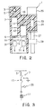
- Figs. 6-9 illustrate an embodiment of the present invention.
- Fig. 6 is an outline cross-sectional view illustrating a vacuum valve 7 or 13 which is to be molded en bloc (the interior of the insulation tube has been omitted) .
- a movable side endplate 67 To a ceramic insulation tube 59 is sealed and attached within a vacuum a movable side endplate 67, to which in turn are attached a fixed side endplate 63 with fixed conductor 61, a movable side conductor 65 and bellows, which are not illustrared in the drawing.
- FIG. 7 is an outline drawing of a the metal cap 69.
- the switchgear 1 is obtained.
- elastomer particles include Kureha EXL 2314 and Nihon Gosei Gomu (Japan Synthetic Rubber: JSR) FX 602.
- Kureha EXL 2314 is dispersed at an optimum ratio of 10% in an epoxy resin with fused silica particles as a filler and a glass transition temperature of 135°C, thus allowing the toughness value to rise from 1.8 Mpam 1/2 to 2.5 Mpam 1/2 .
- Molding was implemented by introducing the resin into the metal mold within a vacuum and performing primary curing in a curing oven. The mold may then be released and secondary curing performed, but instead resin to which an amine complex of boron trichloride had been added as an accelerator to promote reactivity in the epoxy resin at high temperatures was mixed in, the interior of the mold was decompressed at 130°C, and resin which had been defoamed at 50-60°C poured in under pressure from the bottom of the mold, 30 minutes after which it was possible to release the mold. Secondary curing was then performed at 140-150°C to produce a switchgear.
- metal caps 69 are attached to both ends of the vac-uum valves 7 and 13 to ensure that the point of maximum occurrence of heat stress due to the difference in the rate of linear expansion between the ceramic material and the resin comes between the vacuum valves 7 and 13 and the metal caps 69, thus allowing the vacuum valves 7 and 13 to be used irrespective of the end shapes thereof.
- rate of linear expansion in a resin employing a particulate bulking agent is roughly equivalent only to that of copper, its fracture toughness can be improved by dispersing about 10 phr 0.5-5 ⁇ m fine elastomer particles.
- the amount of fine elastomer particles added varies according to particle size, type and particle size of the bulking agent, type of resin and other factors, apart from which both strength and elasticity vary, so that it is difficult to specify the optimum values.
- experiments performed by the authors of the present invention point to 5-20 phr as effective for molding the vacuum valves 7 and 13 en bloc. Inasmuch as it is a particulate bulking agent, foreign materials can also be removed during the process. It is also possible to pour the resin under pressure using a high-speed pressurized gel type mold, which yielded a uniform resin layer after curing.
- the addition of fine elastomer particles has the effect of lowering elasticity, thus facilitating a correspondinq reduction in heat stress.
- the fitting of metal caps 69 to the vacuum valves 7 and 13 means that maximum stress is generated between the endplates and the caps. Even if peeling and cracking occur in this area, there is no effect in terms of insulation because the metal caps 69 and the endplates have the same potential. What is more, the fact that the fracture toughness of the molded resin increases means that any peeling or other faults occurring in this area do not escalate into fissures. If the vacuum valves 7 and 13 are molded without fitting any metal caps 69, fracture toughness is low with only silica or a similar particulate bulking agent.
- a buffer layer may be provided around the vacuum valves 7 and 13 or alternatively milled glass fibers or short fibers may be added to the bulking agent in order to improve toughness before molding.
- the former is time-consuming and troublesome, while with the latter it is often impossible to manage stability of quality. This is due to inability to control dispersion of the bulking agent when pouring the resin unser pressure as in high-speed molding, which leads to cracking. Moreover, any admixture of foreign bodies cannot be filtered out. With particulate molding materials on the other hand, foreign materials can be removed by filtering, and the bulking agent is dispersed even in high-speed molding, making it possible to provide a molded product of stable quality.
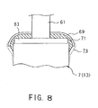
- the inside of the metal caps 69 was formed of the same resin as was used in molding.
- an elastomer 71 is used. With the elastomer 71, a room-temperature vulcanizer may be packed in this space when the metal caps 69 are being fitted, or the elastomer may be molded beforehand and inserted before fitting the metal caps 69.
- maximum stress is generated at the interface between the tip of the elastomer 71 and the insulation tube 35, as a result of which it is best to cover the boundary with glass tape 73 in order to prevent cracking induced by peeling in this area.
- the inlet 75 may be divided into 75a and 75b as illustrated in Fig. 9 , and a plurality of deaeration members 77 and resin pools 79 provided in the metal molds 81.
- the vacuum valves 7, 13 and conductors 3, 5, 19 etc. are introduced into the mold 81 and resin 23 is poured in. Because the inlet 25 is divided into a plurality of inlets, the resin 23 can be packed uniformly without any risk of its not flowing and cavities remaining.
- the inlet 75 is divided into 75a and 75b within the mold 81, but this can also be effected outside the mold 81.
- the resin 23 is pressurized and heated, and is packed into the metal mold as the reaction proceeds, driving the air out in the meantime. However, a void is produced at the tip. This void and the air within the mold are extracted through the deaeration members 77 and resin pools 79. Were it not for the presence of these members 77 and 79, the pressure within the mold would rise as the resin 23 was packed, and a cavity would be generated at the top. For the purpose of extracting air it is preferable that the gap in the deaeration member be as wide as possible.
- the resin 23 which has been poured in will flow out through the deaeration members 77 or by way of the resin pools 79 through the deaeration members 77, and it will be impossible to obtain a satisfactory product.
- the first deaeration member on the bottom side it is preferable for the first deaeration member on the bottom side to be given a conical cross-section in order to make it easy for the resin 23 with voids to pass through. Meanwhile, the resin with voids is held in the resin pool 79. The gap in the deaeration member on the top side is made narrower. By the time the resin reaches this point, the reaction has proceeded, it has gelated and is stopped.
Landscapes
- Engineering & Computer Science (AREA)
- Power Engineering (AREA)
- High-Tension Arc-Extinguishing Switches Without Spraying Means (AREA)
- Gas-Insulated Switchgears (AREA)
Claims (10)
- Interrupteur comprenant :un dispositif (7, 13) d'interruption ayant une valve à vide constituant un disjoncteur à vide et/ou un sectionneur à vide ;un élément (3) d'entrée de ce dispositif (7, 13) d'interruption, par lequel de l'énergie électrique entre de l'extérieur ; etun élément (21) de sortie du dispositif (7, 13) d'interruption, par lequel de l'énergie électrique sort vers l'extérieur ;le dispositif (7, 13) d'interruption étant moulé en bloc dans une couche (23) de résine ensemble avec l'élément (3) d'entrée et l'élément (21) de sortie ;caractérisé en ce quedes capuchons (69) conducteurs en métal, pour protéger électriquement la valve (7, 13) à vide, sont adaptés aux deux surfaces d'extrémité de la valve (7, 13) à vide de manière à recouvrir des plaques (63, 67) d'extrémité de son tube (59) isolant ;un élastomère est introduit dans une région entre les plaques (63, 67) d'extrémité respectives et les capuchons (69) conducteurs en métal ; etles capuchons (69) conducteurs en métal et le dispositif (7, 13) d'interruption sont inclus avec d'autres parties et moulés en bloc.
- Interrupteur suivant la revendication 1,
dans lequel un matériau (73) en fibre de grande résistance est enveloppé autour des surfaces d'extrémité des capuchons (69) conducteurs en métal et du tube (59) isolant du dispositif (7, 13) d'interruption de manière à recouvrir les surfaces d'extrémités du tube (59) isolant. - Interrupteur suivant la revendication 1 ou 2,
dans lequel la valve (7, 13) à vide est un disjoncteur à vide et/ou un sectionneur à vide. - Interrupteur suivant l'une quelconque des revendications 1 à 3,
dans lequel
l'interrupteur est moulé avec la résine (23) et avec un agent gonflant,
l'agent gonflant pour la résine comprend un agent gonflant en silice et des particules d'élastomère d'une finesse 0,5 à 5µm, ces dernières étant dispersées en une proportion de 5 à 20% par rapport à la résine. - Procédé de fabrication d'un interrupteur comprenant les stades dans lesquels :on adapte des capuchons (69) conducteurs en métal, pour protéger respectivement un dispositif (7, 13) d'interruption ayant une valve à vide constituant un disjoncteur à vide ou un sectionneur à vide aux deux surfaces d'extrémité de la valve (7, 13) à vide, de manière à recouvrir des plaques (63, 67) d'extrémité de son tube (59) isolant ;on introduit un élastomère dans une région comprise entre les plaques (63, 67) d'extrémité respectives et des capuchons (69) conducteurs en métal ;on inclut le dispositif (7, 13) d'interruption avec les capuchons (69) conducteurs en métal et d'autres parties ; eton moule le dispositif (7, 13) d'interruption en bloc dans une couche (23) de résine, ensemble avec un élément (3) d'entrée du dispositif (7, 13) d'interruption, par lequel de l'énergie électrique entre de l'extérieur et avec un élément (21) de sortie du dispositif (7, 13) d'interruption, par lequel de l'énergie électrique sort vers l'extérieur.
- Procédé de fabrication d'un interrupteur suivant la revendication 5, dans lequel un agent de vulcanisation à la température ambiante est mis dans ladite région avec l'élastomère (71) ou l'élastomère (71) est moulé à l'avance et inséré avant l'adaptation des capuchons (69) métalliques.
- Procédé de fabrication d'un interrupteur suivant la revendication 5 ou 6, comprenant en outre le stade dans lequel on enroule un matériau (73) en fibre très résistant entre des surfaces d'extrémité des capuchons (69) conducteurs en métal et le tube (59) isolant du dispositif (7, 13) d'interruption de manière à recouvrir les surfaces d'extrémité du tube (59) isolant.
- Procédé de fabrication d'un interrupteur suivant la revendication 5, 6 ou 7, dans lequel on utilise, pour le moulage, un moule (81) métallique ayant une pluralité d'entrées (75a, 75b) de résine, de bassins (79) de résine et d'éléments (77) de sortie d'air.
- Procédé de fabrication d'un interrupteur suivant la revendication 5, 6, 7 ou 8, dans lequel
on moule l'interrupteur avec la résine (23) et un agent gonflant,
l'agent gonflant pour la résine comprend un agent gonflant en silice et des particules d'élastomère d'une finesse 0,5 à 5µm, ces dernières étant dispersées en une proportion de 5 à 20% par rapport à la résine. - Procédé de fabrication d'un interrupteur suivant la revendication 5, 6, 7, 8 ou 9, dans lequel
on moule l'interrupteur en bloc au moyen d'un moulage à grande vitesse en ajoutant un accélérateur de durcissement à la résine afin de favoriser une réaction au-delà de 100° C en mettant sous dépression l'intérieur du moule métallique, en versant la résine dans le moule et en démoulant après 20 à 30 minutes.
Applications Claiming Priority (2)
| Application Number | Priority Date | Filing Date | Title |
|---|---|---|---|
| JP34206699 | 1999-12-01 | ||
| JP34206699A JP3845534B2 (ja) | 1999-12-01 | 1999-12-01 | スイッチギヤ |
Publications (3)
| Publication Number | Publication Date |
|---|---|
| EP1107409A1 EP1107409A1 (fr) | 2001-06-13 |
| EP1107409A8 EP1107409A8 (fr) | 2001-11-14 |
| EP1107409B1 true EP1107409B1 (fr) | 2010-07-07 |
Family
ID=18350903
Family Applications (1)
| Application Number | Title | Priority Date | Filing Date |
|---|---|---|---|
| EP00126303A Expired - Lifetime EP1107409B1 (fr) | 1999-12-01 | 2000-12-01 | Interrupteur et son procédé de fabrication |
Country Status (5)
| Country | Link |
|---|---|
| US (1) | US6897396B2 (fr) |
| EP (1) | EP1107409B1 (fr) |
| JP (1) | JP3845534B2 (fr) |
| CN (1) | CN1201357C (fr) |
| DE (1) | DE60044634D1 (fr) |
Cited By (1)
| Publication number | Priority date | Publication date | Assignee | Title |
|---|---|---|---|---|
| KR20220003347A (ko) * | 2020-07-01 | 2022-01-10 | 한국전력공사 | 결상 감지 진공차단기 및 진공차단기 결상 보호 시스템 |
Families Citing this family (51)
| Publication number | Priority date | Publication date | Assignee | Title |
|---|---|---|---|---|
| JP3845534B2 (ja) | 1999-12-01 | 2006-11-15 | 株式会社東芝 | スイッチギヤ |
| JP2003203546A (ja) * | 2002-01-09 | 2003-07-18 | Toshiba Corp | モールド真空開閉器 |
| JP4247009B2 (ja) * | 2002-03-06 | 2009-04-02 | 株式会社東芝 | スイッチギヤ |
| MXPA02004309A (es) * | 2002-04-30 | 2003-11-06 | Jose Manuel Flores Jauregui | Sistema de proteccion y control monofasico de alta tension con aislamiento seco. |
| NL1020581C2 (nl) * | 2002-05-13 | 2003-11-14 | Holec Holland Nv | Schakelinstallatie voorzien van elektrisch isolerende barriÞre. |
| US6888086B2 (en) * | 2002-09-30 | 2005-05-03 | Cooper Technologies Company | Solid dielectric encapsulated interrupter |
| US7304262B2 (en) * | 2003-04-25 | 2007-12-04 | Cooper Technologies Company | Vacuum encapsulation having an empty chamber |
| DE50304860D1 (de) * | 2003-07-11 | 2006-10-12 | Abb Research Ltd | Hochleistungsschalter mit Kühlrippenanordnung |
| JP4159938B2 (ja) * | 2003-07-25 | 2008-10-01 | 株式会社東芝 | モールド電気機器およびそのモールド方法 |
| DE102004031089B4 (de) * | 2004-06-28 | 2012-08-30 | Abb Technology Ag | Vakuumschaltkammer sowie Verfahren zur Herstellung derselben |
| JP4162664B2 (ja) * | 2005-02-22 | 2008-10-08 | 株式会社日立製作所 | 真空スイッチギヤ |
| DE102005011405B3 (de) * | 2005-03-03 | 2006-11-16 | Siemens Ag | Schaltgerät mit Wärmerohr |
| JP4660303B2 (ja) * | 2005-07-12 | 2011-03-30 | 株式会社東芝 | 固体絶縁スイッチギヤ |
| DE102005039555A1 (de) * | 2005-08-22 | 2007-03-01 | Abb Technology Ltd. | Verfahren zur Herstellung von Schalterpolteilen für Nieder - Mittel - und Hochspannungsschaltanlagen, sowie Schalterpolteil selbst |
| CN101297387B (zh) * | 2005-10-28 | 2011-08-10 | 施恩禧电气有限公司 | 电路断流器组件 |
| JP4197702B2 (ja) | 2006-01-31 | 2008-12-17 | 株式会社日立製作所 | 真空絶縁スイッチギヤ |
| JP2008075069A (ja) | 2006-08-23 | 2008-04-03 | Toshiba Corp | 注型樹脂組成物およびそれを用いた絶縁材料、絶縁構造体 |
| US7807074B2 (en) * | 2006-12-12 | 2010-10-05 | Honeywell International Inc. | Gaseous dielectrics with low global warming potentials |
| JP4760741B2 (ja) * | 2007-03-19 | 2011-08-31 | 三菱電機株式会社 | 真空遮断器 |
| CN101641756A (zh) * | 2007-03-28 | 2010-02-03 | 西门子公司 | 电开关设备 |
| JP4832352B2 (ja) * | 2007-04-05 | 2011-12-07 | 株式会社日立製作所 | 樹脂モールド真空バルブ |
| EP1983623A1 (fr) * | 2007-04-18 | 2008-10-22 | Eaton Electric B.V. | Agencement de refroidissement de conducteur dans une installation électrique |
| JP4940018B2 (ja) * | 2007-05-15 | 2012-05-30 | 株式会社東芝 | 固体絶縁スイッチギヤ |
| US7902480B2 (en) * | 2007-06-13 | 2011-03-08 | Hitachi, Ltd. | Vacuum insulated switchgear |
| EP2071687A1 (fr) * | 2007-12-10 | 2009-06-17 | ABB Technology AG | Ensemble de commutation moyenne tension ou haute tension |
| FR2925755B1 (fr) * | 2007-12-21 | 2012-08-03 | Schneider Electric Ind Sas | Isolation d'un dispositif de coupure de type ampoule a vide par surmoulage |
| EP2107659A1 (fr) * | 2008-04-01 | 2009-10-07 | Zurecon AG | Barre omnibus |
| ATE497246T1 (de) * | 2008-09-01 | 2011-02-15 | Abb Technology Ag | Niederspannungs-, mittelspannungs- oder hochspannungsanordnung |
| PL2414444T3 (pl) * | 2009-04-02 | 2013-09-30 | Huntsman Adv Mat Licensing Switzerland Gmbh | Bezpośrednie przeformowanie |
| JP4906892B2 (ja) * | 2009-08-12 | 2012-03-28 | 株式会社日立製作所 | スイッチギヤ |
| JP5292225B2 (ja) * | 2009-08-26 | 2013-09-18 | 株式会社東芝 | モールド真空バルブ |
| JP5431220B2 (ja) * | 2010-03-19 | 2014-03-05 | 株式会社東芝 | 固体絶縁スイッチギヤの放熱装置 |
| RU2447536C2 (ru) * | 2010-07-06 | 2012-04-10 | Федеральное государственное унитарное предприятие "Всероссийский электротехнический институт имени В.И. Ленина" | Устройство управляемой коммутации |
| AU2011276938B2 (en) * | 2010-07-07 | 2015-02-12 | Siemens Ltd. | An electrical isolator |
| JP5423657B2 (ja) * | 2010-11-30 | 2014-02-19 | 株式会社日立製作所 | 開閉器ユニット及び開閉器ユニットを搭載するスイッチギヤ |
| JP2012231576A (ja) * | 2011-04-25 | 2012-11-22 | Toshiba Corp | ガス絶縁スイッチギヤ |
| JP5749565B2 (ja) * | 2011-05-19 | 2015-07-15 | 株式会社東芝 | 樹脂モールド真空バルブ |
| US9177742B2 (en) | 2011-10-18 | 2015-11-03 | G & W Electric Company | Modular solid dielectric switchgear |
| JP5868501B2 (ja) * | 2012-05-29 | 2016-02-24 | 株式会社日立製作所 | 開閉器ユニットまたはスイッチギヤ |
| CN104201041B (zh) * | 2014-08-15 | 2015-10-21 | 浙江道笃智能开关有限公司 | 组合固封极柱及其工作原理 |
| CN106663923B (zh) * | 2014-08-20 | 2019-05-31 | 株式会社东芝 | 固体绝缘设备的散热装置 |
| CN104377073B (zh) * | 2014-12-05 | 2017-10-03 | 北京合锐清合电气有限公司 | 接地开关及基于该接地开关的固体绝缘环网柜 |
| CN104701064B (zh) * | 2015-03-26 | 2015-12-09 | 江苏现代电力科技股份有限公司 | 基于柔性分合闸技术的智能集成中压交流真空开关设备 |
| EP3109880A1 (fr) * | 2015-06-22 | 2016-12-28 | ABB Schweiz AG | Piece polaire a moyenne ou basse tension avec au moins un element dissipateur de chaleur |
| DE102016218355A1 (de) * | 2016-09-23 | 2018-03-29 | Siemens Aktiengesellschaft | Unterbrechbare Kabelmuffenanordnung |
| JP6968764B2 (ja) * | 2018-08-07 | 2021-11-17 | 株式会社日立産機システム | 真空開閉器及びその製造方法 |
| CN110794269B (zh) * | 2019-11-07 | 2021-09-07 | 云南电网有限责任公司电力科学研究院 | 一种绿色绝缘气体绝缘强度计算方法 |
| WO2023281574A1 (fr) * | 2021-07-05 | 2023-01-12 | 三菱電機株式会社 | Procédé servant à la fabrication d'une soupape à vide |
| CN119234364A (zh) * | 2022-05-10 | 2024-12-31 | 三菱电机株式会社 | 固体绝缘母线 |
| US12476441B2 (en) * | 2022-08-24 | 2025-11-18 | Siemens Energy Global GmbH & Co. KG | Arrangement of a current transformer core at an interface with a conical connector |
| JP7542784B1 (ja) * | 2024-03-08 | 2024-08-30 | 三菱電機株式会社 | 真空遮断器 |
Citations (4)
| Publication number | Priority date | Publication date | Assignee | Title |
|---|---|---|---|---|
| US3513425A (en) * | 1969-05-21 | 1970-05-19 | Gen Electric | Modular electrical conductor termination system |
| US3812314A (en) * | 1971-08-23 | 1974-05-21 | Gen Electric | High power electrical bushing having a vacuum switch encapsulated therein |
| US3955167A (en) * | 1975-01-08 | 1976-05-04 | Mcgraw-Edison Company | Encapsulated vacuum fuse assembly |
| US4982059A (en) * | 1990-01-02 | 1991-01-01 | Cooper Industries, Inc. | Axial magnetic field interrupter |
Family Cites Families (7)
| Publication number | Priority date | Publication date | Assignee | Title |
|---|---|---|---|---|
| EP0186688A1 (fr) * | 1984-06-21 | 1986-07-09 | The Electricity Council | Dispositif commutateur a haute tension |
| US5387772A (en) * | 1993-11-01 | 1995-02-07 | Cooper Industries, Inc. | Vacuum switch |
| US5597992A (en) * | 1994-12-09 | 1997-01-28 | Cooper Industries, Inc. | Current interchange for vacuum capacitor switch |
| MY119298A (en) | 1996-09-13 | 2005-04-30 | Cooper Ind Inc | Encapsulated vacuum interrupter and method of making same |
| JP3623333B2 (ja) | 1997-01-28 | 2005-02-23 | 株式会社東芝 | 受変電設備装置 |
| JP3164033B2 (ja) * | 1997-10-03 | 2001-05-08 | 株式会社日立製作所 | 母線の接続構造及び絶縁カバー |
| JP3845534B2 (ja) | 1999-12-01 | 2006-11-15 | 株式会社東芝 | スイッチギヤ |
-
1999
- 1999-12-01 JP JP34206699A patent/JP3845534B2/ja not_active Expired - Fee Related
-
2000
- 2000-12-01 DE DE60044634T patent/DE60044634D1/de not_active Expired - Lifetime
- 2000-12-01 US US09/726,411 patent/US6897396B2/en not_active Expired - Lifetime
- 2000-12-01 EP EP00126303A patent/EP1107409B1/fr not_active Expired - Lifetime
- 2000-12-01 CN CNB001347438A patent/CN1201357C/zh not_active Expired - Fee Related
Patent Citations (4)
| Publication number | Priority date | Publication date | Assignee | Title |
|---|---|---|---|---|
| US3513425A (en) * | 1969-05-21 | 1970-05-19 | Gen Electric | Modular electrical conductor termination system |
| US3812314A (en) * | 1971-08-23 | 1974-05-21 | Gen Electric | High power electrical bushing having a vacuum switch encapsulated therein |
| US3955167A (en) * | 1975-01-08 | 1976-05-04 | Mcgraw-Edison Company | Encapsulated vacuum fuse assembly |
| US4982059A (en) * | 1990-01-02 | 1991-01-01 | Cooper Industries, Inc. | Axial magnetic field interrupter |
Cited By (1)
| Publication number | Priority date | Publication date | Assignee | Title |
|---|---|---|---|---|
| KR20220003347A (ko) * | 2020-07-01 | 2022-01-10 | 한국전력공사 | 결상 감지 진공차단기 및 진공차단기 결상 보호 시스템 |
Also Published As
| Publication number | Publication date |
|---|---|
| EP1107409A1 (fr) | 2001-06-13 |
| US20010002666A1 (en) | 2001-06-07 |
| JP2001160342A (ja) | 2001-06-12 |
| DE60044634D1 (de) | 2010-08-19 |
| US6897396B2 (en) | 2005-05-24 |
| EP1107409A8 (fr) | 2001-11-14 |
| CN1201357C (zh) | 2005-05-11 |
| CN1305208A (zh) | 2001-07-25 |
| JP3845534B2 (ja) | 2006-11-15 |
Similar Documents
| Publication | Publication Date | Title |
|---|---|---|
| EP1107409B1 (fr) | Interrupteur et son procédé de fabrication | |
| CN101268536B (zh) | 用于低、中、高压开关设备的开关电极部件的制造方法以及开关电极部件本身 | |
| KR101249785B1 (ko) | 플러그-인 부싱, 및 이와 같은 부싱을 갖는 고전압 설비 | |
| RU2479061C2 (ru) | Изоляция коммутационного устройства типа вакуумного картриджа посредством формования заливкой | |
| EP2593953B1 (fr) | Procédé permettant de produire une partie de pôle de disjoncteur | |
| KR101039733B1 (ko) | 고체절연 가공선로용 고전압 부하개폐기 | |
| CN101395686A (zh) | 箱壳式真空断路器 | |
| EP3214709A1 (fr) | Appareillage de commutation | |
| KR102517402B1 (ko) | 회로 차단 장치 | |
| JP4832352B2 (ja) | 樹脂モールド真空バルブ | |
| KR101213631B1 (ko) | 고체절연 차단기 극의 감압 엘라스토머 층 | |
| CN109791858B (zh) | 高压开关装置和带有高压开关装置的开关设备以及高压开关装置的制造方法 | |
| KR101091683B1 (ko) | 개폐기/차단기용 조립식 절연하우징 | |
| US20040232113A1 (en) | Electric switching device for medium or high voltage | |
| US5902980A (en) | Insulating component for high-voltage equipment | |
| EP2540468B1 (fr) | Moule de coulée | |
| CN101567275A (zh) | 断路器元件相柱的一次外包真空灭弧室的制造方法及模具 | |
| US4037187A (en) | Metal clad insulating circuit breaker | |
| KR20040021654A (ko) | 진공밸브 | |
| CN101203991B (zh) | 具有至少三个壳体部分的基本上管状延伸的封闭壳体 | |
| CN101116156B (zh) | 避雷器及测量避雷器漏泄电流的方法 | |
| JP2011055567A (ja) | スイッチギヤ及びその製造方法 | |
| JP2009205801A (ja) | 真空開閉器 | |
| CN102306588B (zh) | 一种组合式真空灭弧室极柱 | |
| CN119348022B (zh) | 一种极柱模具 |
Legal Events
| Date | Code | Title | Description |
|---|---|---|---|
| PUAI | Public reference made under article 153(3) epc to a published international application that has entered the european phase |
Free format text: ORIGINAL CODE: 0009012 |
|
| 17P | Request for examination filed |
Effective date: 20001201 |
|
| AK | Designated contracting states |
Kind code of ref document: A1 Designated state(s): CH DE LI |
|
| AX | Request for extension of the european patent |
Free format text: AL;LT;LV;MK;RO;SI |
|
| RIN1 | Information on inventor provided before grant (corrected) |
Inventor name: SEKIYA, HIROKI, C/O TOSHIBA CORPORATION Inventor name: ITO, YOSHIHIRO, C/O TOSHIBA CORPORATION Inventor name: MIYAGAWA, MASARU, C/O TOSHIBA CORPORATION Inventor name: SHIMIZU, TOSHIO, C/O TOSHIBA CORPORATION Inventor name: MAKISHIMA, SATOSHI, C/O TOSHIBA CORPORATION Inventor name: KINOSHITA, SUSUMU, C/O TOSHIBA CORPORATION |
|
| AKX | Designation fees paid |
Free format text: CH DE LI |
|
| 17Q | First examination report despatched |
Effective date: 20061013 |
|
| GRAP | Despatch of communication of intention to grant a patent |
Free format text: ORIGINAL CODE: EPIDOSNIGR1 |
|
| GRAS | Grant fee paid |
Free format text: ORIGINAL CODE: EPIDOSNIGR3 |
|
| GRAA | (expected) grant |
Free format text: ORIGINAL CODE: 0009210 |
|
| AK | Designated contracting states |
Kind code of ref document: B1 Designated state(s): CH DE LI |
|
| REG | Reference to a national code |
Ref country code: CH Ref legal event code: EP |
|
| REF | Corresponds to: |
Ref document number: 60044634 Country of ref document: DE Date of ref document: 20100819 Kind code of ref document: P |
|
| PLBE | No opposition filed within time limit |
Free format text: ORIGINAL CODE: 0009261 |
|
| STAA | Information on the status of an ep patent application or granted ep patent |
Free format text: STATUS: NO OPPOSITION FILED WITHIN TIME LIMIT |
|
| 26N | No opposition filed |
Effective date: 20110408 |
|
| REG | Reference to a national code |
Ref country code: DE Ref legal event code: R097 Ref document number: 60044634 Country of ref document: DE Effective date: 20110408 |
|
| REG | Reference to a national code |
Ref country code: CH Ref legal event code: PL |
|
| PG25 | Lapsed in a contracting state [announced via postgrant information from national office to epo] |
Ref country code: LI Free format text: LAPSE BECAUSE OF NON-PAYMENT OF DUE FEES Effective date: 20101231 Ref country code: CH Free format text: LAPSE BECAUSE OF NON-PAYMENT OF DUE FEES Effective date: 20101231 |
|
| PGFP | Annual fee paid to national office [announced via postgrant information from national office to epo] |
Ref country code: DE Payment date: 20161123 Year of fee payment: 17 |
|
| REG | Reference to a national code |
Ref country code: DE Ref legal event code: R119 Ref document number: 60044634 Country of ref document: DE |
|
| PG25 | Lapsed in a contracting state [announced via postgrant information from national office to epo] |
Ref country code: DE Free format text: LAPSE BECAUSE OF NON-PAYMENT OF DUE FEES Effective date: 20180703 |