EP1107414A2 - Verfahren zur Unterspannungs-Ueberwachung einer Netzspannung und Unterspannungsausloeser - Google Patents
Verfahren zur Unterspannungs-Ueberwachung einer Netzspannung und Unterspannungsausloeser Download PDFInfo
- Publication number
- EP1107414A2 EP1107414A2 EP00250409A EP00250409A EP1107414A2 EP 1107414 A2 EP1107414 A2 EP 1107414A2 EP 00250409 A EP00250409 A EP 00250409A EP 00250409 A EP00250409 A EP 00250409A EP 1107414 A2 EP1107414 A2 EP 1107414A2
- Authority
- EP
- European Patent Office
- Prior art keywords
- voltage
- current
- magnet
- undervoltage
- mains
- Prior art date
- Legal status (The legal status is an assumption and is not a legal conclusion. Google has not performed a legal analysis and makes no representation as to the accuracy of the status listed.)
- Granted
Links
- 238000000034 method Methods 0.000 title claims abstract description 11
- 238000012544 monitoring process Methods 0.000 title claims description 14
- 239000003990 capacitor Substances 0.000 claims abstract description 17
- 229910004670 OPV1 Inorganic materials 0.000 claims description 9
- 229910004667 OPV2 Inorganic materials 0.000 claims description 8
- 230000001105 regulatory effect Effects 0.000 claims description 2
- 230000004913 activation Effects 0.000 abstract description 2
- 238000001514 detection method Methods 0.000 abstract 3
- 230000003213 activating effect Effects 0.000 abstract 1
- 230000002045 lasting effect Effects 0.000 abstract 1
- 230000002688 persistence Effects 0.000 abstract 1
- 230000033228 biological regulation Effects 0.000 description 1
- 230000007423 decrease Effects 0.000 description 1
- 230000003111 delayed effect Effects 0.000 description 1
- 230000005611 electricity Effects 0.000 description 1
- 238000012423 maintenance Methods 0.000 description 1
- 230000035939 shock Effects 0.000 description 1
- 230000001960 triggered effect Effects 0.000 description 1
Images
Classifications
-
- H—ELECTRICITY
- H02—GENERATION; CONVERSION OR DISTRIBUTION OF ELECTRIC POWER
- H02H—EMERGENCY PROTECTIVE CIRCUIT ARRANGEMENTS
- H02H3/00—Emergency protective circuit arrangements for automatic disconnection directly responsive to an undesired change from normal electric working condition with or without subsequent reconnection ; integrated protection
- H02H3/24—Emergency protective circuit arrangements for automatic disconnection directly responsive to an undesired change from normal electric working condition with or without subsequent reconnection ; integrated protection responsive to undervoltage or no-voltage
- H02H3/247—Emergency protective circuit arrangements for automatic disconnection directly responsive to an undesired change from normal electric working condition with or without subsequent reconnection ; integrated protection responsive to undervoltage or no-voltage having timing means
-
- H—ELECTRICITY
- H02—GENERATION; CONVERSION OR DISTRIBUTION OF ELECTRIC POWER
- H02H—EMERGENCY PROTECTIVE CIRCUIT ARRANGEMENTS
- H02H3/00—Emergency protective circuit arrangements for automatic disconnection directly responsive to an undesired change from normal electric working condition with or without subsequent reconnection ; integrated protection
- H02H3/006—Calibration or setting of parameters
Definitions
- the invention relates to a method for undervoltage monitoring a mains voltage with a magnet for actuation a circuit breaker, a line voltage monitor Threshold circuit with which the holding current of the magnet in the event of an undervoltage in the network to a lower holding current is controlled, the latter by a charging capacitor is supported, and controlled by a timer after the time has elapsed with a permanent undervoltage there is an off signal for the magnet of the circuit breaker.
- the invention further relates to a method working undervoltage release.
- Undervoltage releases are used in electrical systems to protect consumers who are at a voltage drop could be damaged in the network. So that not everyone brief voltage drop to switch off the consumer leads, the trigger is briefly, for. B. by 3 s, delayed.
- the holding current also during the delay time, in which may be completely disconnected from the mains can be maintained, it is once by a charging capacitor supported in the associated with the magnet Driver circuit is included, and he is going to order another in turn, to be able to keep this charging capacitor small, in reduced its value.
- the magnet is operated in series with a switching transistor, which is clocked in this way during a suit and during normal holding becomes that the current through the magnet is substantially constant is held.
- the magnet becomes a higher resistance than when pulling in and holding in Series connected.
- the tension of these each in series with the resistors connected to the magnet simultaneously provide one Reference value for constant current control.
- the holding current is reduced to a much lower mean regulated down as the starting current.
- the invention has for its object a method and specify an undervoltage release with which the power loss the tripping magnets of circuit breakers with Undervoltage release lowered and that of the undervoltage release can be built small.
- the holding current is reduced to a fraction of the starting current and the current during the undervoltage delay time reduced to a fraction of the holding current.
- the holding current can be reduced to a value at which a sufficient Contact force is maintained even when shaken. Since the current is squared into the power loss, thus a reduction in output to 1/16 of the power loss in holding mode possible. During the delay time a further power loss reduction to approx. Reach 1/400 of the power loss.
- the pull-in current can optionally be a continuous or clocked Scheme to be limited.
- the holding current is expedient by clocking to an average current limited by about 1/4 of the starting current. While the delay time, the current will continue to about 1/20 of the Starting current is reduced, deliberately in this operation Vibration resistance of the switch is dispensed with.
- a suitable undervoltage release is according to the invention constructed so that the output of the threshold circuit via a resistor with a capacitor connected in parallel and a current setpoint during the delay time Output of the timer to the second input of the Constant current controller are performed.
- the setpoint of the current given by the magnet flows.
- the threshold circuit When switched on by the capacitor at the output the threshold circuit has a high voltage on the input of the constant current regulator, so that the magnet attracts with high current. After the capacitor voltage has decayed is about the resistance at the output of the threshold circuit a lower current setpoint is specified than for the Suit of the magnet. In the event of undervoltage, the timer is used then a further setpoint reduction during a delay time performed.
- a peculiarity of the solution is the maintenance of one Monitoring current in an emergency stop, as in the following embodiment still to be explained.
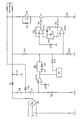
- the drawing shows a possible circuit variant for one Undervoltage release.
- the line voltage U N or a line-proportional voltage is rectified with a bridge rectifier.
- the DC voltage feeds a magnet M of a circuit breaker.
- a charging capacitor C1 is simultaneously charged with the direct voltage via a diode D1.
- an electronic switch V1 In series with the magnet M are an electronic switch V1 and a current measuring resistor R1 switched.
- the electronic Switch V1 is controlled by a constant current controller, which in a known manner from the operational amplifiers OPV1 and OPV2 is formed.
- the OPV1 operational amplifier receives a signal via resistor R2 at its plus input for the actual value of the current and at its minus input a signal for the setpoint of the current.
- the regulation takes place by cyclical activation of the operational amplifier OPV2, caused by an out of a resistor R3 and a capacitor C2 existing timer to which the Output of the operational amplifier OPV1 via a diode D2 is switched.
- the DC voltage is applied to the input of the circuit via a Voltage divider, consisting of resistors R6, R7, R8, divided and fed to a comparator OPV3.
- the exit of the Comparator OPV3 is through a parallel connection of a resistor R9 with a capacitor C3 and a diode D3 with the setpoint input of the constant voltage controller OPV1 / OPV2 connected.
- the output of the comparator is on one Time module N1 led, its output via a resistor R10 also to the setpoint input of the constant current controller is led.
- the comparator OPV3 provides an undervoltage at its input fixed, it reaches its switching point. His exit receives a negative pulse that triggers the time module N1, during a set delay time, usually approx. 3 s, the current setpoint continues via resistor R10 lowers. Compared to the starting current, the current can be in the delay phase be reduced to about 1/20.
- the current through the magnet M may be maintained by charging the charging capacitor C1.
- the switch trips. If the mains voltage rises again above the switching point of the comparator OPV3, an increased current setpoint for specified the pull-in current so that the magnet tighten again can.
- the magnet M can also be operated by opening the emergency stop contacts become. In this case, a restart at Another option was to enable closing of the emergency stop contacts Current path created via resistor R6 and a diode D4, which is the flow of a low monitoring current allowed by the solenoid.
- the electronic switch V1 remains open in this operating state, for which the constant current controller a setpoint via a voltage divider R11 / R12 is specified. It becomes a monitoring current in the Maintain milliampere range.
- the monitoring current forms a shunt to the resistors R7, R8, so that the input voltage at the comparator OPV3 below the switching voltage decreases and thus undervoltage is simulated.
- the Closing the emergency stop contacts is a renewed tightening pulse triggered and the circuit breaker switched on again.
- the monitoring current also flows in the event of undervoltage tripping further by the magnet M, if one - reduced - DC voltage is present. Because the monitoring current is very small, it has for the operation of the circuit breaker except for an emergency stop.
Landscapes
- Emergency Protection Circuit Devices (AREA)
Abstract
Description
Claims (6)
- Verfahren zur Unterspannungs-Überwachung einer Netzspannung mit einem Magneten zur Betätigung eines Leistungsschalters, einer die Netzspannung überwachenden Schwellwertschaltung, mit der der Haltestrom des Magneten bei Unterspannung des Netzes auf einen geringeren Haltestrom gesteuert wird, wobei letzterer durch einen Ladekondensator gestützt wird, und durch die ein Zeitglied angesteuert wird, nach dessen Zeitablauf bei bleibender Unterspannung ein Aus-Signal für den Magneten des Leistungsschalters erfolgt, dadurch gekennzeichnet, daß der Haltestrom auf einen Bruchteil des Anzugsstromes und der Strom während der Verzögerungszeit bei Unterspannung auf einen Bruchteil des Haltestromes reduziert wird.
- Verfahren nach Anspruch 1,
dadurch gekennzeichnet,
daß die Stromreduzierung durch Takten eines mit dem Magneten in Reihe geschalteten elektronischen Schalters bewirkt wird. - Verfahren nach Anspruch 2,
dadurch gekennzeichnet,
daß der elektronische Schalter konstantstromgeregelt wird. - Verfahren nach einem der Ansprüche 1 bis 3,
dadurch gekennzeichnet,
daß nach einer Notausschaltung des Magneten der Stromfluß durch den Magneten mit einem nicht für das Halten des Magnetankers ausreichenden Überwachungsstrom aufrechterhalten und an der Schwellwertschaltung Unterspannung simuliert wird. - Unterspannungsauslöser zur Überwachung einer Netzspannung (UN) mit einem von einer netzproportionalen Gleichspannung versorgten Magneten (M) zur Betätigung eines Leistungsschalters,zur Durchführung des Verfahren nach einem der Ansprüche 1 bis 4, dadurch gekennzeichnet,einer die Netzspannung (UN) anhand der netzproportionalen Gleichspannung überwachenden Schwellwertschaltung (OPV3) , einer mit dem Ausgang der Schwellwertschaltung (OPV3) verbundenen Zeitglied (N1),einem mit der netzproportionalen Gleichspannung beaufschlagten Ladekondensator (C1) und einem über einen Konstantstromregler (OPV1, OPV2) geregelten elektronischen Schalter (V1) in Reihe mit dem Magneten (M), wobei die an einem in Reihe mit dem Magneten (M) und dem elektronischen Schalter (V1) geschalteten Widerstand (R1) abgenommene Spannung an einen ersten Eingang des Konstantstromreglers (OPV1, OPV2) und der Ausgang des Zeitgliedes (N1) an den zweiten Eingang des Konstantstromreglers (OPV1,OPV2) geführt ist,
daß der Ausgang der Schwellwertschaltung (OPV3) über einen Widerstand (R9) mit parallel geschaltetem Kondensator(C3) und ein einen Stromsollwert während der Verzögerungszeit vorgebender Ausgang des Zeitgliedes (N1) an den zweiten Eingang des Konstantstromreglers (OPV1, OPV2) geführt sind. - Unterspannungsauslöser nach Anspruch 5,
dadurch gekennzeichnet,
daß eine über eine Diode (D4) von einem an der netzproportionalen Gleichspannung liegenden Spannungsteiler (R6, R7, R8) , von dem auch die Eingangsspannung des Schwellwertschalters (OPV3) abgenommen ist, abgegriffene Spannung über einen Notaus-Unterbrechungsschalter an den Magneten (M) geführt ist und der zweite Eingang des Konstantstromreglers (OPV1, OPV2) mit der an einem an der netzproportionalen Gleichspannung liegenden Spannungsteiler (R11, R12) abgenommenen Spannung beaufschlagt ist.
Applications Claiming Priority (2)
| Application Number | Priority Date | Filing Date | Title |
|---|---|---|---|
| DE19959775A DE19959775A1 (de) | 1999-12-07 | 1999-12-07 | Verfahren zur Unterspannungs-Überwachung einer Netzspannung und Unterspannungsauslöser |
| DE19959775 | 1999-12-07 |
Publications (3)
| Publication Number | Publication Date |
|---|---|
| EP1107414A2 true EP1107414A2 (de) | 2001-06-13 |
| EP1107414A3 EP1107414A3 (de) | 2004-05-12 |
| EP1107414B1 EP1107414B1 (de) | 2005-07-27 |
Family
ID=7932274
Family Applications (1)
| Application Number | Title | Priority Date | Filing Date |
|---|---|---|---|
| EP00250409A Expired - Lifetime EP1107414B1 (de) | 1999-12-07 | 2000-11-29 | Verfahren zur Unterspannungs-Ueberwachung einer Netzspannung und Unterspannungsausloeser |
Country Status (2)
| Country | Link |
|---|---|
| EP (1) | EP1107414B1 (de) |
| DE (2) | DE19959775A1 (de) |
Cited By (2)
| Publication number | Priority date | Publication date | Assignee | Title |
|---|---|---|---|---|
| CN105023815A (zh) * | 2015-06-29 | 2015-11-04 | 天津市百利电气有限公司 | 塑料外壳式断路器电子欠电压脱扣器 |
| CN108258971A (zh) * | 2018-01-11 | 2018-07-06 | 北京新能源汽车股份有限公司 | 一种电机控制方法、装置、控制器及汽车 |
Family Cites Families (3)
| Publication number | Priority date | Publication date | Assignee | Title |
|---|---|---|---|---|
| US4025823A (en) * | 1975-07-11 | 1977-05-24 | Westinghouse Electric Corporation | Circuit breaker including undervoltage release mechanism and control circuit |
| JPH0746651B2 (ja) * | 1984-12-18 | 1995-05-17 | 株式会社ゼクセル | ソレノイド駆動装置 |
| DE19507936A1 (de) * | 1995-02-24 | 1996-09-05 | Siemens Ag | Unterspannungsauslöser mit einem Elektromagnet |
-
1999
- 1999-12-07 DE DE19959775A patent/DE19959775A1/de not_active Withdrawn
-
2000
- 2000-11-29 DE DE50010825T patent/DE50010825D1/de not_active Expired - Lifetime
- 2000-11-29 EP EP00250409A patent/EP1107414B1/de not_active Expired - Lifetime
Cited By (2)
| Publication number | Priority date | Publication date | Assignee | Title |
|---|---|---|---|---|
| CN105023815A (zh) * | 2015-06-29 | 2015-11-04 | 天津市百利电气有限公司 | 塑料外壳式断路器电子欠电压脱扣器 |
| CN108258971A (zh) * | 2018-01-11 | 2018-07-06 | 北京新能源汽车股份有限公司 | 一种电机控制方法、装置、控制器及汽车 |
Also Published As
| Publication number | Publication date |
|---|---|
| DE19959775A1 (de) | 2001-06-13 |
| EP1107414A3 (de) | 2004-05-12 |
| EP1107414B1 (de) | 2005-07-27 |
| DE50010825D1 (de) | 2005-09-01 |
Similar Documents
| Publication | Publication Date | Title |
|---|---|---|
| DE102008064659B4 (de) | Schaltungsanordnung und Ansteuerschaltung für ein Netzteil, Computernetzteil und Verfahren zum Schalten eines Netzteils | |
| DE2516951C3 (de) | Steuereinrichtung zum Abschalten des Antriebsmotors eines elektrisch betriebenen Schraubers | |
| DE2538705A1 (de) | Stromempfindliches schutzschaltsystem | |
| US4183071A (en) | Control circuit for resetting circuit breaker UVR solenoid | |
| EP3414778A1 (de) | Schutzschaltung für ein photovoltaik (pv)-modul, verfahren zum betrieb der schutzschaltung und photovoltaik (pv)-anlage mit einer derartigen schutzschaltung | |
| DE19742038A1 (de) | Verfahren zur Zustandserkennung bei einem Magnetventil | |
| DE3842883A1 (de) | Elektrische beleuchtungseinrichtung und insbesondere fuer diese geeignete schutzschaltung | |
| DE2624316A1 (de) | Automatisches ein- und ausschaltgeraet fuer elektrische wechselstromnetze | |
| DE102019212661A1 (de) | Elektronisches Schutzschaltgerät und Verfahren | |
| EP1636808B1 (de) | Verfahren und schaltungsanordnung zum betreiben eines magnetantriebes | |
| DE2748354A1 (de) | Einrichtung zum erfassen eines vakuumverlustes in schaltungsunterbrechern vom vakuum-typ fuer einen mehrphasigen vakuum-wechselstromleistungsschalter | |
| EP0183108A1 (de) | Elektrische Kurzschluss-Überwachungsanordnung für drehzahlgeregelte Drehstrommotoren einschliesslich deren Zuleitungen | |
| EP1107414B1 (de) | Verfahren zur Unterspannungs-Ueberwachung einer Netzspannung und Unterspannungsausloeser | |
| EP0893870B9 (de) | Netzspannungsversorgungseinrichtung | |
| EP0811266A1 (de) | Unterspannungsauslöser mit einem elektromagnet | |
| EP0140093B1 (de) | Schütz mit Steuerstufe und Überstromauslöser | |
| EP0915547A2 (de) | Elektronisches Überlastrelais | |
| EP1388191A1 (de) | Umgehungsschaltung für den überstromauslöser eines niederspannungs-leistungsschalters | |
| EP1218997B1 (de) | Unterspannungauslöser mit elektromagnet und getaktetem haltestromkreis | |
| DE4033801C1 (de) | ||
| EP1005710B1 (de) | Fehlerstromschutzschalter | |
| DE102004046810A1 (de) | Elektronischer Schutzschalter mit einstellbarer Auslösecharakteristik | |
| DE767215C (de) | Schaltungsanordnung zur selbsttaetigen UEberwachung von mit Gleichstrom betriebenen Blinklichtanlagen | |
| DE4336033C2 (de) | Schaltungsanordnung zur Ladung von Batterien | |
| DE2851648C2 (de) |
Legal Events
| Date | Code | Title | Description |
|---|---|---|---|
| PUAI | Public reference made under article 153(3) epc to a published international application that has entered the european phase |
Free format text: ORIGINAL CODE: 0009012 |
|
| AK | Designated contracting states |
Kind code of ref document: A2 Designated state(s): AT BE CH CY DE DK ES FI FR GB GR IE IT LI LU MC NL PT SE TR |
|
| AX | Request for extension of the european patent |
Free format text: AL;LT;LV;MK;RO;SI |
|
| PUAL | Search report despatched |
Free format text: ORIGINAL CODE: 0009013 |
|
| AK | Designated contracting states |
Kind code of ref document: A3 Designated state(s): AT BE CH CY DE DK ES FI FR GB GR IE IT LI LU MC NL PT SE TR |
|
| AX | Request for extension of the european patent |
Extension state: AL LT LV MK RO SI |
|
| 17P | Request for examination filed |
Effective date: 20040601 |
|
| 17Q | First examination report despatched |
Effective date: 20040723 |
|
| GRAP | Despatch of communication of intention to grant a patent |
Free format text: ORIGINAL CODE: EPIDOSNIGR1 |
|
| AKX | Designation fees paid |
Designated state(s): DE FR GB IT |
|
| GRAS | Grant fee paid |
Free format text: ORIGINAL CODE: EPIDOSNIGR3 |
|
| GRAA | (expected) grant |
Free format text: ORIGINAL CODE: 0009210 |
|
| AK | Designated contracting states |
Kind code of ref document: B1 Designated state(s): DE FR GB IT |
|
| REG | Reference to a national code |
Ref country code: GB Ref legal event code: FG4D Free format text: NOT ENGLISH |
|
| GBT | Gb: translation of ep patent filed (gb section 77(6)(a)/1977) |
Effective date: 20050727 |
|
| REF | Corresponds to: |
Ref document number: 50010825 Country of ref document: DE Date of ref document: 20050901 Kind code of ref document: P |
|
| ET | Fr: translation filed | ||
| PLBE | No opposition filed within time limit |
Free format text: ORIGINAL CODE: 0009261 |
|
| STAA | Information on the status of an ep patent application or granted ep patent |
Free format text: STATUS: NO OPPOSITION FILED WITHIN TIME LIMIT |
|
| 26N | No opposition filed |
Effective date: 20060428 |
|
| PGFP | Annual fee paid to national office [announced via postgrant information from national office to epo] |
Ref country code: GB Payment date: 20091112 Year of fee payment: 10 |
|
| GBPC | Gb: european patent ceased through non-payment of renewal fee |
Effective date: 20101129 |
|
| PG25 | Lapsed in a contracting state [announced via postgrant information from national office to epo] |
Ref country code: GB Free format text: LAPSE BECAUSE OF NON-PAYMENT OF DUE FEES Effective date: 20101129 |
|
| PGFP | Annual fee paid to national office [announced via postgrant information from national office to epo] |
Ref country code: IT Payment date: 20121129 Year of fee payment: 13 |
|
| PGFP | Annual fee paid to national office [announced via postgrant information from national office to epo] |
Ref country code: FR Payment date: 20121214 Year of fee payment: 13 |
|
| REG | Reference to a national code |
Ref country code: FR Ref legal event code: ST Effective date: 20140731 |
|
| PG25 | Lapsed in a contracting state [announced via postgrant information from national office to epo] |
Ref country code: IT Free format text: LAPSE BECAUSE OF NON-PAYMENT OF DUE FEES Effective date: 20131129 |
|
| PG25 | Lapsed in a contracting state [announced via postgrant information from national office to epo] |
Ref country code: FR Free format text: LAPSE BECAUSE OF NON-PAYMENT OF DUE FEES Effective date: 20131202 |
|
| PGFP | Annual fee paid to national office [announced via postgrant information from national office to epo] |
Ref country code: DE Payment date: 20150119 Year of fee payment: 15 |
|
| REG | Reference to a national code |
Ref country code: DE Ref legal event code: R119 Ref document number: 50010825 Country of ref document: DE |
|
| PG25 | Lapsed in a contracting state [announced via postgrant information from national office to epo] |
Ref country code: DE Free format text: LAPSE BECAUSE OF NON-PAYMENT OF DUE FEES Effective date: 20160601 |