EP1107423A1 - Stator à employer dans un moteur électrique ou dynamo - Google Patents
Stator à employer dans un moteur électrique ou dynamo Download PDFInfo
- Publication number
- EP1107423A1 EP1107423A1 EP99309616A EP99309616A EP1107423A1 EP 1107423 A1 EP1107423 A1 EP 1107423A1 EP 99309616 A EP99309616 A EP 99309616A EP 99309616 A EP99309616 A EP 99309616A EP 1107423 A1 EP1107423 A1 EP 1107423A1
- Authority
- EP
- European Patent Office
- Prior art keywords
- stator
- units
- end section
- central axis
- column
- Prior art date
- Legal status (The legal status is an assumption and is not a legal conclusion. Google has not performed a legal analysis and makes no representation as to the accuracy of the status listed.)
- Withdrawn
Links
- 238000004804 winding Methods 0.000 claims abstract description 22
- 239000000696 magnetic material Substances 0.000 claims 1
- 229910052751 metal Inorganic materials 0.000 description 5
- 239000002184 metal Substances 0.000 description 5
- 238000009434 installation Methods 0.000 description 2
- 239000000463 material Substances 0.000 description 2
- 229910000831 Steel Inorganic materials 0.000 description 1
- 239000000853 adhesive Substances 0.000 description 1
- 230000001070 adhesive effect Effects 0.000 description 1
- 229910052782 aluminium Inorganic materials 0.000 description 1
- XAGFODPZIPBFFR-UHFFFAOYSA-N aluminium Chemical compound [Al] XAGFODPZIPBFFR-UHFFFAOYSA-N 0.000 description 1
- 239000004020 conductor Substances 0.000 description 1
- -1 for example Substances 0.000 description 1
- 238000004519 manufacturing process Methods 0.000 description 1
- 239000007769 metal material Substances 0.000 description 1
- 238000000034 method Methods 0.000 description 1
- 239000000843 powder Substances 0.000 description 1
- 229920006395 saturated elastomer Polymers 0.000 description 1
- 238000007493 shaping process Methods 0.000 description 1
- 239000010959 steel Substances 0.000 description 1
- 238000003466 welding Methods 0.000 description 1
Images





Classifications
-
- H—ELECTRICITY
- H02—GENERATION; CONVERSION OR DISTRIBUTION OF ELECTRIC POWER
- H02K—DYNAMO-ELECTRIC MACHINES
- H02K1/00—Details of the magnetic circuit
- H02K1/06—Details of the magnetic circuit characterised by the shape, form or construction
- H02K1/12—Stationary parts of the magnetic circuit
- H02K1/14—Stator cores with salient poles
- H02K1/141—Stator cores with salient poles consisting of C-shaped cores
-
- H—ELECTRICITY
- H02—GENERATION; CONVERSION OR DISTRIBUTION OF ELECTRIC POWER
- H02K—DYNAMO-ELECTRIC MACHINES
- H02K2201/00—Specific aspects not provided for in the other groups of this subclass relating to the magnetic circuits
- H02K2201/06—Magnetic cores, or permanent magnets characterised by their skew
Definitions
- the present invention relates to a stator, and more particularly to an improved structure of stator for use in a electro-motor or dynamo.
- FIG 23 shows a stator for use in a electro-motor or dynamo.
- This structure of stator 80 is comprised of a metal core consisting of a stack of metal plates 81 of thickness about within 0.35mm ⁇ 0.5mm.
- Each metal plate 81 comprises a plurality of teeth 82 and a plurality of inside notches 83 alternatively arranged on the inside around the circular center opening thereof.
- This structure of stator 80 wastes lots of metal plate material (the portions at the inside notches 83 and center portion 84 ), and requires special machines, such as winding machine, shaping machine, and binding machine, etc. for winding the windings on the metal plates 81 .
- special machines such as winding machine, shaping machine, and binding machine, etc.
- stator which can be alternatively arranged to fit different design requirements. It is another object of the present invention to provide a stator, which is easy and costless to manufacture. It is still another object of the present invention to provide a stator, which has independent stator units for easy installation of the windings separately, enabling the windings to be wound round each stator unit in a saturated manner, so as to improve the strength of magnetic field.
- the stator is comprised of a plurality of stator units.
- Each stator unit is comprised of a column and winding means wound round the column.
- the column comprises a first end section, a second end section, and a middle section.
- the first end section and the second end section are formed integral with two distal ends of the middle section, and turned toward an inner side of the column.
- the stator units are arranged around a central axis on which the rotor is rotated.
- the stator units are independent members.
- the windings are respectively wound round the column of each stator unit.
- the longitudinal axis of each stator can be arranged in parallel or perpendicular to the central axis, or at an angle relative to the central axis.
- the stator units can be arranged on a plane around the central axis.
- the stator units can be arranged at different layers and spaced along the central axis, such that a difference of elevation exists between the stators at each two adjacent layers.
- Figure 1 shows a column for a stator according to the present invention.
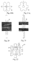
- Figure 1A - 1D show the side views for different shapes of column.
- Figure 2 shows an alternate form of the column for stator according to the present invention.
- Figure 3 shows another alternate form of the column for stator according to the present invention.
- Figure 4 is a sectional view of a stator according to a first embodiment of the present invention.
- Figure 5 is a sectional view of a stator according to a second embodiment of the present invention.
- Figure 6 is a sectional view of a stator according to a third embodiment of the present invention.
- Figure 7 is a sectional view of a stator according to a fourth embodiment of the present invention.
- Figure 8 is a perspective view of the stator according to the fourth embodiment of the present invention.
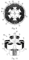
- Figure 9 is a sectional view of a stator according to a fifth embodiment of the present invention.
- Figure 10 is a perspective view of the stator according to the fifth embodiment of the present invention.
- Figure 11 is a perspective view of a stator according to a sixth embodiment of the present invention.
- Figure 12 is a sectional view of the stator according to the sixth embodiment of the present invention.
- Figure 13 is a sectional view of a stator according to a seventh embodiment of the present invention.
- Figure 14 is a sectional view of a stator according to an eighth embodiment of the present invention.
- FIG. 15 is a perspective view of the stator according to the eighth embodiment of the present invention.
- Figures 16 through 18 show three different forms of rotors according to the present invention.
- Figure 19 illustrates a stator according to a ninth embodiment of the present invention.
- Figure 20 and 21 show two other different forms of rotors according to the present invention, and Figure 20A and 21A are the top view hereof.
- Figure 23 is a perspective view of a stator according to the prior art.
- a stator 90 is shown comprised of three stator units 10 .
- Each stator unit 10 is comprised of a column 19 , and a winding 30 .
- the column 19 as shown in Figure 1, extends longitudinally along a longitudinal axis 41 from a topside 16 toward a bottom side 17 , comprising a first end section 11 , a second end section 12 , and a middle section 13 .
- the first end section 11 and the second end section 12 are respectively formed integral with two distal ends of the middle section 13 , and turned toward the inner side 14 of the column 19 (after installation of the winding and connection of electric current to the winding, the first end section 11 and the second end section 12 form the N pole and the S pole respectively).
- the side opposite to the inner side 14 is the outer side 15 .
- the column 19 is made of magnetically conductive material, for example, powder metal material, or a plurality of magnetically conductive plates 20 arranged in a stack in the direction of the longitudinal axis 41 or from the inner side 14 toward the outer side 15.
- the magnetically conductive plates 20 can be obtained from steel plates.
- the winding 30 is made of enameled wire wound round the column 19 through multiple turns over the top side 16 , the inner side 14 , the bottom side 17 , and the outer side 15 .
- Winding holder means 31 is preferably provided at the column 19 to hold the winding 30 .
- each stator unit 10 is provided at the first end section 11 and the second end section 12 , and the stator units 10 are equiangularly spaced around the rotor 91 with the inner side 14 of each stator unit 10 facing the central axis 93 on which the rotor 91 is rotated.
- This arrangement forms a 6-pole (three N poles and three S poles) stator 90 .
- FIG. 5 shows an alternate form of the present invention.
- the winding 30 of each stator unit 10 is provided at the middle section 13 , and the first end section 11 and second end section 12 of each stator unit 10 each have an end edge 18 smoothed curved inwards for close contact with the rotor 91 .
- FIG. 6 shows another alternate form of the present invention.
- the stator 90 is comprised of six stator units 10 , and the windings 30 are respectively fastened to the first end section 11 at the column 19 of one stator unit 10 and the second end section 12 of the column 19 of another stator unit 10 .
- FIGS 7 and 8 show still another alternate form of the present invention.
- the stator 90 is a 6-pole stator having three stator units 10 arranged into three layers spaced in the direction of the central axis 93 , and there is a difference of elevation in the direction of the longitudinal axis 41 between each two adjacent stator units 10 (the stator unit 10 at each layer is provided at a different location relative to the longitudinal axis 41 ).
- Figures 9 and 10 show still another alternate form of the present invention.
- the stator 90 is a 12-pole stator comprised of six stator units 10 arranged in two sets. The two sets of stator units 10 are spaced in the direction of the central axis 93 , and staggered.
- the longitudinal axis 41 is parallel to the central axis 93 .
- Figures from 11 through 13 show still other alternate forms of the present invention, in which the longitudinal axis 41 of each stator unit 10 respectively extends perpendicular to the central axis 93 .
- the efficiency of stator unit 10 shown in Figures from 11 through 13 is better than the efficiency of stator unit 10 shown in Figures from 4 through 10.
- the stator 90 is a 12-pole stator comprised of six stator units 10 spaced from one another at 60° around the central axis 93 .
- the rotor 91 can be used like Figure 16, 17, 18, 20, and 21.
- the S poles and N poles of the rotor 91 are respectively extended in an oblique direction, and alternatively arranged in parallel.
- the rotor 91 is comprised of two vertically spaced aluminum cast stator elements (non-permanent magnets).
- the rotor 91 is comprised of two magnets vertically spaced in reversed directions.
- Figure 20 and 21 also show a different shape of rotors 91, especially with different shape of top view shown in Figure 20A and 21A.
- the embodiment shown in Figure 13 is a two-layer design based on the embodiment shown in Figures 11 and 12, in which the stator elements 10 at the bottom layer and the stator elements 10 at the top layer are staggered (in Figure 13, only the bottom layer stator elements 10 are shown).
- each stator unit 10 defines with the central axis 93 a contained angle ⁇ . This arrangement enables a relatively thicker winding 30 to be respectively wound round the column 19 of each stator unit 10 .
- FIG 19 shows still another alternate form of the present invention, in which the stator 90 is a 6-pole stator comprised of three stator units 10 arranged in such a direction that the inner side 14 of each stator unit 10 is disposed in parallel to the longitudinal axis 41 of the respective stator unit 10 , and the longitudinal axis 41 of each of the three stator units 10 respectively extends perpendicular to the central axis 93 .
- the rotor 91 is shaped like a disk, and supported on a shaft 914 in locating means 50 by bearings 911 .
- the rotor 91 comprises a plurality of magnets 913 (6 poles) arranged around the border. This arrangement enables the rotor 91 to be rotated on the shaft 914 .
- the aforesaid locating means 50 can be a shell, and the stator units 10 of the stator 90 are respectively fastened to the shell 50 on the inside by an adhesive, screw means, or a welding apparatus.
- the stator units 10 can be arranged on a rack, and then a plastic shell is molded on the stator units 10 and the rack.
- Figure 22 show a rotor 60 which comprises several rotor units 69 mounted on a rotor base 65, wherein the material of rotor units 69 are magnetic.
- Each rotor unit 69 is similar to the column 19 of stator illustrated as above, which comprises a first end section 61 , a second end section 62 , and a middle section 63 , wherein the inner side of each rotor unit 69 being arranged toward outside.
- rotor unit 69 such as top side, inner side and etc, please refer to the description of column 19 .
- the rotor 60 can be used with the stator units 10 such as shown in Figures from 11 through 13
- Figure 1A - 1D show the side views for different shapes of column.
Landscapes
- Engineering & Computer Science (AREA)
- Power Engineering (AREA)
- Iron Core Of Rotating Electric Machines (AREA)
Priority Applications (1)
| Application Number | Priority Date | Filing Date | Title |
|---|---|---|---|
| EP99309616A EP1107423A1 (fr) | 1999-11-30 | 1999-11-30 | Stator à employer dans un moteur électrique ou dynamo |
Applications Claiming Priority (1)
| Application Number | Priority Date | Filing Date | Title |
|---|---|---|---|
| EP99309616A EP1107423A1 (fr) | 1999-11-30 | 1999-11-30 | Stator à employer dans un moteur électrique ou dynamo |
Publications (1)
| Publication Number | Publication Date |
|---|---|
| EP1107423A1 true EP1107423A1 (fr) | 2001-06-13 |
Family
ID=8241773
Family Applications (1)
| Application Number | Title | Priority Date | Filing Date |
|---|---|---|---|
| EP99309616A Withdrawn EP1107423A1 (fr) | 1999-11-30 | 1999-11-30 | Stator à employer dans un moteur électrique ou dynamo |
Country Status (1)
| Country | Link |
|---|---|
| EP (1) | EP1107423A1 (fr) |
Cited By (1)
| Publication number | Priority date | Publication date | Assignee | Title |
|---|---|---|---|---|
| CN108494118A (zh) * | 2018-04-19 | 2018-09-04 | 李亚兵 | 节能发电机和动力系统 |
Citations (5)
| Publication number | Priority date | Publication date | Assignee | Title |
|---|---|---|---|---|
| US1501372A (en) * | 1921-08-17 | 1924-07-15 | Robinson Henry | Magnetic circuit of electrical motors and dynamos |
| GB629684A (en) * | 1947-03-03 | 1949-09-26 | Frederick Arthur Summerlin | Improvements in or relating to alternating-current machines |
| FR1453957A (fr) * | 1965-07-30 | 1966-08-22 | Dispositif à induction électromagnétique à noyaux feuilletés | |
| US3921017A (en) * | 1973-03-13 | 1975-11-18 | Skf Ind Trading & Dev | Electric motor |
| GB2312332A (en) * | 1996-04-16 | 1997-10-22 | Tai Her Yang | Magnetic circuit structure for an electric machine |
-
1999
- 1999-11-30 EP EP99309616A patent/EP1107423A1/fr not_active Withdrawn
Patent Citations (5)
| Publication number | Priority date | Publication date | Assignee | Title |
|---|---|---|---|---|
| US1501372A (en) * | 1921-08-17 | 1924-07-15 | Robinson Henry | Magnetic circuit of electrical motors and dynamos |
| GB629684A (en) * | 1947-03-03 | 1949-09-26 | Frederick Arthur Summerlin | Improvements in or relating to alternating-current machines |
| FR1453957A (fr) * | 1965-07-30 | 1966-08-22 | Dispositif à induction électromagnétique à noyaux feuilletés | |
| US3921017A (en) * | 1973-03-13 | 1975-11-18 | Skf Ind Trading & Dev | Electric motor |
| GB2312332A (en) * | 1996-04-16 | 1997-10-22 | Tai Her Yang | Magnetic circuit structure for an electric machine |
Cited By (1)
| Publication number | Priority date | Publication date | Assignee | Title |
|---|---|---|---|---|
| CN108494118A (zh) * | 2018-04-19 | 2018-09-04 | 李亚兵 | 节能发电机和动力系统 |
Similar Documents
| Publication | Publication Date | Title |
|---|---|---|
| US6188159B1 (en) | Stator used for dynamo or electromotor | |
| EP0872943B1 (fr) | Machine tornante électrodynamique à aimants permanents ayant un stator a bobinage concentré | |
| US8890387B2 (en) | Stator and motor | |
| EP1073179B1 (fr) | Enroulement pour stator sans encoche et méthode pour fabriquer un tel enroulement | |
| JP5484688B2 (ja) | 電機子ラミネーション | |
| JP6640910B2 (ja) | 回転電機 | |
| US8400040B2 (en) | Permanent magnet type rotary electric machine | |
| US11569717B2 (en) | Axial flux rotary electric machine | |
| JPH114555A (ja) | 永久磁石回転電機 | |
| US12046972B2 (en) | Motor and stator bus bar | |
| KR20180006306A (ko) | 축방향 플럭스 다이나모일렉트릭 머신용 스테이터 및 코일 | |
| US12021424B2 (en) | Coil, and stator, rotor, and motor equipped with same, and manufacturing method for coil | |
| US20210273537A1 (en) | Method of manufacturing stator | |
| CN110612655B (zh) | 马达 | |
| US10644547B2 (en) | Armature | |
| US20040074079A1 (en) | Stator for an electrical machine | |
| CN110462986B (zh) | 马达 | |
| US7329973B2 (en) | Rotary electric machine | |
| EP2019476A2 (fr) | Moteurs électriques | |
| JP2021101608A (ja) | ノイズを最小にする寸法比率を有する回転電気機械 | |
| US20150061433A1 (en) | Electricity collection and distribution ring | |
| CN110521090B (zh) | 马达 | |
| EP1107423A1 (fr) | Stator à employer dans un moteur électrique ou dynamo | |
| JP7280070B2 (ja) | ステータ及びブラシレスモータ | |
| CN118157422B (zh) | 直流有刷电机 |
Legal Events
| Date | Code | Title | Description |
|---|---|---|---|
| PUAI | Public reference made under article 153(3) epc to a published international application that has entered the european phase |
Free format text: ORIGINAL CODE: 0009012 |
|
| AK | Designated contracting states |
Kind code of ref document: A1 Designated state(s): AT BE CH CY DE DK ES FI FR GB GR IE IT LI LU MC NL PT SE |
|
| AX | Request for extension of the european patent |
Free format text: AL;LT;LV;MK;RO;SI |
|
| AKX | Designation fees paid | ||
| REG | Reference to a national code |
Ref country code: DE Ref legal event code: 8566 |
|
| STAA | Information on the status of an ep patent application or granted ep patent |
Free format text: STATUS: THE APPLICATION IS DEEMED TO BE WITHDRAWN |
|
| 18D | Application deemed to be withdrawn |
Effective date: 20011214 |