EP1107429A2 - Verbindungen für die Statorwicklung einer rotierenden elektrischen Maschine - Google Patents
Verbindungen für die Statorwicklung einer rotierenden elektrischen Maschine Download PDFInfo
- Publication number
- EP1107429A2 EP1107429A2 EP00126180A EP00126180A EP1107429A2 EP 1107429 A2 EP1107429 A2 EP 1107429A2 EP 00126180 A EP00126180 A EP 00126180A EP 00126180 A EP00126180 A EP 00126180A EP 1107429 A2 EP1107429 A2 EP 1107429A2
- Authority
- EP
- European Patent Office
- Prior art keywords
- component
- rotating machine
- set forth
- bobbin
- conductors
- Prior art date
- Legal status (The legal status is an assumption and is not a legal conclusion. Google has not performed a legal analysis and makes no representation as to the accuracy of the status listed.)
- Withdrawn
Links
Images


Classifications
-
- H—ELECTRICITY
- H02—GENERATION; CONVERSION OR DISTRIBUTION OF ELECTRIC POWER
- H02K—DYNAMO-ELECTRIC MACHINES
- H02K3/00—Details of windings
- H02K3/46—Fastening of windings on the stator or rotor structure
- H02K3/52—Fastening salient pole windings or connections thereto
- H02K3/521—Fastening salient pole windings or connections thereto applicable to stators only
- H02K3/522—Fastening salient pole windings or connections thereto applicable to stators only for generally annular cores with salient poles
-
- H—ELECTRICITY
- H02—GENERATION; CONVERSION OR DISTRIBUTION OF ELECTRIC POWER
- H02K—DYNAMO-ELECTRIC MACHINES
- H02K2203/00—Specific aspects not provided for in the other groups of this subclass relating to the windings
- H02K2203/03—Machines characterised by the wiring boards, i.e. printed circuit boards or similar structures for connecting the winding terminations
-
- H—ELECTRICITY
- H02—GENERATION; CONVERSION OR DISTRIBUTION OF ELECTRIC POWER
- H02K—DYNAMO-ELECTRIC MACHINES
- H02K2203/00—Specific aspects not provided for in the other groups of this subclass relating to the windings
- H02K2203/09—Machines characterised by wiring elements other than wires, e.g. bus rings, for connecting the winding terminations
-
- H—ELECTRICITY
- H02—GENERATION; CONVERSION OR DISTRIBUTION OF ELECTRIC POWER
- H02K—DYNAMO-ELECTRIC MACHINES
- H02K2203/00—Specific aspects not provided for in the other groups of this subclass relating to the windings
- H02K2203/12—Machines characterised by the bobbins for supporting the windings
Definitions
- This invention relates to a component for a rotating electrical machine and more particularly to an improved arrangement for forming the windings and electrical connections for a component that cooperates with relatively rotatable permanent magnets for machine operation.
- a rotating or fixed element that comprises a core having a plurality of teeth around which individual windings are wound. Frequently, these windings are positioned on bobbins that surround the core teeth and which are electrically non-conductive.
- This invention is adapted to be embodied in a component of a rotating electrical machine that is comprised of a plurality of coil windings each wound on the pole teeth of a core through a bobbin.
- the bobbin has portions that surround the pole teeth of the core and around which the conductors of the coils are wound.
- the bobbin carries a plurality of wiring conductors and each has one end connected to at least one of the coil ends and the other end connected to one external connection terminal.
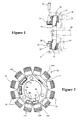
- Figure 1 is a cross sectional view taken through a rotating electrical machine constructed in accordance with an embodiment of the invention and showing, in this embodiment, the stator in cross-section and solid lines with the remaining components of the machine being shown in phantom. This view is taken generally along the line 1-0-5 of Fig. 4.
- Fig. 2 is a front view of the stator.
- Fig. 3 is a perspective view of the stator core.
- Fig. 4 is a front view of the stator coils showing the winding direction thereof.
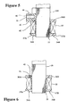
- Fig. 5 is an enlarged cross sectional view taken along the line O-5 of Fig. 4.
- Fig. 6 is an enlarged cross section along line O-6 of Fig. 4.
- Fig. 7 is a front view of one of the bobbin halves.
- Fig. 8 is a view looking in the same direction as Fig. 7 showing the arrangement of the inserted wiring conductors in solid lines with the body of the bobbin half shown in phantom.
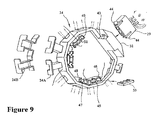
- Fig. 9 is an exploded perspective view of the bobbin half shown in Figs. 7 and 8 and showing the relation to the associated electrical connectors or terminals and the other bobbin half that is shown broken away.
- Fig. 10 is an exploded front view of one of the external conncctions and associated electrical connector shown in Fig. 9.
- Fig. I 1 is a perspective view of the components shown in Fig. 10 in the coupled state.
- Fig. 12. is a cross sectional view showing the first step coupling movement of the external connection terminal and its associated electrical connector shown in Figs. 10 and 11.
- Fig. 13. is a cross sectional view, in part similar to Figure 12, showing the completion of the electrical connection
- a rotating electrical machine constructed in accordance with an embodiment of the invention is identified generally by the reference numeral 21.
- This invention deals primarily with the coil windings and terminal connections of this machine 21, which, in this embodiment, is embodied in a stator 22 having a plurality, namely 12, of pole pieces or cores 23 and associated bobbins of a bobbin assembly 24 on which coil windings 25 are wound, in a manner to be described.
- the stator 22 is fixed against rotation in any suitable manner.
- the stator 22 cooperates with a rotating cup-shape member 26 that carries a plurality of circumferentially spaced permanent magnets 27.
- This cup-shape member 26 is affixed for rotation with a shaft 28.
- the rotating machine 21 may comprise an electrical generator wherein a voltage is induced in the coil windings 25 upon rotation of the magnets 27 to provide electrical current output.
- the mechanism may comprise an electric motor as will become apparent to those skilled in the art.
- the invention is described in conjunction with a stator, certain facets of the invention may also be employed where the rotor carries the coil windings.
- FIG. 1 One of the male electrical connectors for the external electrical connection appears in Fig. 1 and is identified generally by the reference numeral 29.
- This male electrical connector 29 cooperates with a female external terminal or connector 31 formed on the stator 22 around an annular opening 32 formed therein, which a portion of the shaft 28 passes.
- the core 23 is formed of a laminated construction consisting of silicon or carbon steel plates laminated with insulating layers. This forms the plurality of cores or pole pieces 23, certain of which are numbered alphabetically, that extend outwardly from a hub portion 34. Each of the pole pieces 23 has an enlarged headed portion.
- the bobbin assembly indicated generally by the reference numeral 24 is associated with the cores 23 and is formed from a pair of mating pieces or halves 24A and 24B.
- the bobbin halves 24A and 24B are snugly received around the pole pieces 23 and each has a pair of flanges 36 and 37 around which the individual coil windings 25 are wound in a manner which will be described.
- the bobbin halves 24A and 24B are made from a suitable insulating resin by injection molding.
- a number of conductors which may be formed from stamped metallic pieces, are embedded in one or both of the bobbin halves 24A and 24B. In the illustrated embodiment, all of these conductors are mounted in a side enlargement of the bobbin half 24A and these conductors appear best in Fig. 8.
- the conductors indicated generally by the reference numerals 39, 41 and 42, have common output terminals that lie in side by side relationship as best seen in Figure 3 and which form terminal ends Y, B and W, designated as color coding of the individual conductors 39, 41 and 42, respectively.
- the conductors 39, 41 and 42 are formed preferably as stamped blanks of a highly conductive material such as copper. Opposite ends of these conductors 39, 41 and 42 are associated with certain of the coil windings 25 in a manner to be described so as to simplify the connections thereto and the entire electrical structure and to avoid the necessity of having soldered connections.
- the external female communication terminal 31 encircles the terminal ends Y, B and W of the individual conductors 39, 41 and 42 so as to receive the connector 29 when pressed together in a radial direction and form the desired electrical connections. This construction appears best in Figs. 1, 2 and 9 through 13.
- the bobbin half 24A is formed with a pair of openings 43 that receive tabs 44 formed on the external female connector 29. This provides a snap together connection being made as seen in these three figures. Wires Y, B and W are carried by the connector 29 and cooperate with the terminal ends of the corresponding designation. Thus, electrically power can be extracted through these conductors.
- This external female terminal 31 is formed adjacent a pole piece indicated at 23A.
- the conductor 41 extends from its terminal end B in a clockwise direction around the bobbin half 24A and terminates adjacent the fifth pole (23B) counting in a clockwise direction from the pole 23A at a terminal 45.
- This terminal 45 extends up to the base of the magnetic pole 23B and terminates in a further female electrical connector 46 formed in the bobbin half 24A and integrally with it.
- the conductor 42 extends circumferentially around from the first pole 23A past the fifth pole 23B to the sixth pole 23C where it forms a terminal end 47.
- This terminal end 47 terminates in a further female electrical connector 48 formed integrally with the bobbin half 24A.
- the conductor 39 extends in a counter clockwise direction from the terminal end Y to a terminal end formed adjacent the tenth pole 23D at a terminal end 49.
- This terminal end 49 extends to the base of the core 23D and terminates in a female external electrical connector 51.
- this housing portion 52 serves no purpose. However, it can be utilized in other embodiments as an electrical connector where other winding arrangements in addition to those, which will be described shortly, are employed.
- the twelve poles 23 and their associated windings 25 are formed in two groups, the first consisting of a winding N1 which begins at the terminal end 47 where it is connected by means of inserting it into an opening formed in a tip of the terminal end 47 thus avoiding the necessity for soldering.
- This winding is then wound around the sixth pole 23C and specifically the portion of the bobbin 24 that is associated with it and then without interruption wound around the next three poles 23 and terminates at a conductor terminal found at the base of the eleventh pole 23D in the electrical connector 49.
- a second winding N2 begins at a terminal formed in the electrical connector 51 and is wound around the eleventh pole 23D and more specifically its bobbin and the succeeding eight poles traveling in the clockwise direction to terminate at the pole 23B where it terminates in the electrical connector 46.
- the housing pieces 46 and 48 have two conductor receiving openings while the housing portion 51 has three openings. These openings bridge the respective conductors to which the coil ends are affixed and receive coupling devices 53, in the case of the two-terminal openings 46 and 48, and 54, in the case of the three-opening housing 51.
- These connectors 53 and 54 have internal wiring that form the completion of the circuits between the coil ends so as to further simplify the overall wiring and again avoid soldered terminals.
- the described construction provides a very compact coil winding arrangement for a rotating machine and one in which no soldered connections are required. Also, because of the good electrical connections the power loses are minimized and the efficiency of the device significantly improves. In addition, because there are no soldered connections, the likelihood of failure of the connections is substantially reduced and hence, the life of the associated machine can be prolonged while continuing to maintain a good power output or efficiency depending upon whether the device operates as a generator or a motor.
- An electrical machine having a plurality of pole pieces surrounded by bobbins and upon which individual coil windings are formed.
- the bobbins are formed by a insulating material in which are embedded electrical connectors that have terminal ends that afford connection to the coil windings and to an external connection for either deriving electrical power in the case the machine operates as a generator or receiving power in the event the device operates as a motor.
- cost is reduced and at the same time the device is more compact and more efficiency.
Landscapes
- Engineering & Computer Science (AREA)
- Power Engineering (AREA)
- Insulation, Fastening Of Motor, Generator Windings (AREA)
Applications Claiming Priority (5)
| Application Number | Priority Date | Filing Date | Title |
|---|---|---|---|
| US723016 | 1985-04-15 | ||
| JP34221699 | 1999-12-01 | ||
| JP34221699A JP2001169495A (ja) | 1999-12-01 | 1999-12-01 | 回転機のステータ |
| US09/723,016 US7187099B1 (en) | 1999-12-01 | 2000-11-27 | Component of a rotating electrical machine |
| 2001-02-02 |
Publications (2)
| Publication Number | Publication Date |
|---|---|
| EP1107429A2 true EP1107429A2 (de) | 2001-06-13 |
| EP1107429A3 EP1107429A3 (de) | 2005-06-15 |
Family
ID=26577189
Family Applications (1)
| Application Number | Title | Priority Date | Filing Date |
|---|---|---|---|
| EP00126180A Withdrawn EP1107429A3 (de) | 1999-12-01 | 2000-11-30 | Verbindungen für die Statorwicklung einer rotierenden elektrischen Maschine |
Country Status (2)
| Country | Link |
|---|---|
| EP (1) | EP1107429A3 (de) |
| CN (1) | CN1340897A (de) |
Cited By (3)
| Publication number | Priority date | Publication date | Assignee | Title |
|---|---|---|---|---|
| WO2005020408A3 (de) * | 2003-08-18 | 2005-06-23 | Vorwerk Co Interholding | Reluktanzmotor und verfahren zum wickeln eines reluktanzmotors |
| EP1542339A4 (de) * | 2002-07-22 | 2008-07-02 | Nsk Ltd | Motor, verfahren zur herstellung eines motors und ansteuersteuereinrichtung für den motor |
| WO2013076442A3 (en) * | 2011-11-22 | 2015-02-26 | Cummins Generator Technologies Limited | Connection unit for connecting the windings of a rotating electric machine |
Families Citing this family (1)
| Publication number | Priority date | Publication date | Assignee | Title |
|---|---|---|---|---|
| CN101478187B (zh) * | 2008-01-04 | 2011-04-06 | 建准电机工业股份有限公司 | 马达线圈 |
Family Cites Families (6)
| Publication number | Priority date | Publication date | Assignee | Title |
|---|---|---|---|---|
| US4287446A (en) * | 1979-06-27 | 1981-09-01 | Amp Incorporated | Stator for stepper motor |
| JPS5947954A (ja) * | 1982-09-10 | 1984-03-17 | Honda Motor Co Ltd | フライホイール式磁石発電機の製造方法 |
| FR2651935B1 (fr) * | 1989-09-08 | 1994-10-07 | Mitsuba Electric Mfg Co | Enroulements d'un stator de magneto-generateur. |
| JPH09261905A (ja) * | 1996-03-25 | 1997-10-03 | Kokusan Denki Co Ltd | 電機子 |
| JPH10309067A (ja) * | 1997-05-01 | 1998-11-17 | Tamagawa Seiki Co Ltd | レゾルバのステータ構造 |
| JPH11103551A (ja) * | 1997-09-29 | 1999-04-13 | Sawafuji Electric Co Ltd | アウタロータ型多極発電機におけるコイル接続構造 |
-
2000
- 2000-11-30 EP EP00126180A patent/EP1107429A3/de not_active Withdrawn
- 2000-12-01 CN CN 00134499 patent/CN1340897A/zh active Pending
Cited By (3)
| Publication number | Priority date | Publication date | Assignee | Title |
|---|---|---|---|---|
| EP1542339A4 (de) * | 2002-07-22 | 2008-07-02 | Nsk Ltd | Motor, verfahren zur herstellung eines motors und ansteuersteuereinrichtung für den motor |
| WO2005020408A3 (de) * | 2003-08-18 | 2005-06-23 | Vorwerk Co Interholding | Reluktanzmotor und verfahren zum wickeln eines reluktanzmotors |
| WO2013076442A3 (en) * | 2011-11-22 | 2015-02-26 | Cummins Generator Technologies Limited | Connection unit for connecting the windings of a rotating electric machine |
Also Published As
| Publication number | Publication date |
|---|---|
| EP1107429A3 (de) | 2005-06-15 |
| CN1340897A (zh) | 2002-03-20 |
Similar Documents
| Publication | Publication Date | Title |
|---|---|---|
| US6583529B2 (en) | Wiring arrangement for a rotating electrical machine | |
| EP0905860B1 (de) | Spulenverbindungsvorrichtung für einen Ausseläufermultipolegenerator | |
| KR100438993B1 (ko) | 회전전기 | |
| US6333579B1 (en) | Stator for outer rotor-type multi-pole generator | |
| US6285109B1 (en) | Small motor with improved connecting structure between coil, riser and varistor | |
| US5057732A (en) | Electric motor having a molded housing and connector plates projected thereon | |
| US4074159A (en) | Dynamo-electric machine | |
| US6703751B2 (en) | Dynamo-electric machine | |
| CA2458833A1 (en) | Stator for rotating electrical machine | |
| US20110001373A1 (en) | Rotating Electric Machine and Manufacturing Method Thereof | |
| US5243246A (en) | Connector assembly for a rotary electric machine | |
| US7187099B1 (en) | Component of a rotating electrical machine | |
| US6617742B2 (en) | Star connected rotor | |
| JP2000060073A (ja) | 回転電機及びその製造方法 | |
| EP1107429A2 (de) | Verbindungen für die Statorwicklung einer rotierenden elektrischen Maschine | |
| US20220224209A1 (en) | Electric motor with injection moulded stator | |
| US6774525B2 (en) | Dynamo-electric machine | |
| US6362555B1 (en) | Small motor with improved connecting structure between coil, riser and varistor | |
| US6836048B2 (en) | Coil winding arrangement for electrical machine | |
| JPS58172949A (ja) | 内燃機関の点火装置用のマグネツト発電機 | |
| US6617741B2 (en) | Commutator for electric rotary machine and manufacturing method thereof | |
| JPH04183257A (ja) | 永久磁石型パルスモータ | |
| EP1389822A2 (de) | Wicklungsanordnung für eine elektrische Maschine | |
| JPH0538119A (ja) | ブラシレスモータ | |
| JP2002165397A (ja) | アウタロータ型多極発電機用ステータの巻線構造 |
Legal Events
| Date | Code | Title | Description |
|---|---|---|---|
| PUAI | Public reference made under article 153(3) epc to a published international application that has entered the european phase |
Free format text: ORIGINAL CODE: 0009012 |
|
| AK | Designated contracting states |
Kind code of ref document: A2 Designated state(s): AT BE CH CY DE DK ES FI FR GB GR IE IT LI LU MC NL PT SE TR |
|
| AX | Request for extension of the european patent |
Free format text: AL;LT;LV;MK;RO;SI |
|
| RAP1 | Party data changed (applicant data changed or rights of an application transferred) |
Owner name: KABUSHIKI KAISHA MORIC |
|
| PUAL | Search report despatched |
Free format text: ORIGINAL CODE: 0009013 |
|
| AK | Designated contracting states |
Kind code of ref document: A3 Designated state(s): AT BE CH CY DE DK ES FI FR GB GR IE IT LI LU MC NL PT SE TR |
|
| AX | Request for extension of the european patent |
Extension state: AL LT LV MK RO SI |
|
| AKX | Designation fees paid |
Designated state(s): DE FR IT |
|
| STAA | Information on the status of an ep patent application or granted ep patent |
Free format text: STATUS: THE APPLICATION IS DEEMED TO BE WITHDRAWN |
|
| 18D | Application deemed to be withdrawn |
Effective date: 20051216 |