EP1107575A2 - Procédé d'impression d'images numériques avec plusieurs colorants avec substantiellement la même couleur - Google Patents
Procédé d'impression d'images numériques avec plusieurs colorants avec substantiellement la même couleur Download PDFInfo
- Publication number
- EP1107575A2 EP1107575A2 EP00204192A EP00204192A EP1107575A2 EP 1107575 A2 EP1107575 A2 EP 1107575A2 EP 00204192 A EP00204192 A EP 00204192A EP 00204192 A EP00204192 A EP 00204192A EP 1107575 A2 EP1107575 A2 EP 1107575A2
- Authority
- EP
- European Patent Office
- Prior art keywords
- colorants
- colorant
- look
- control signal
- tables
- Prior art date
- Legal status (The legal status is an assumption and is not a legal conclusion. Google has not performed a legal analysis and makes no representation as to the accuracy of the status listed.)
- Withdrawn
Links
- 239000003086 colorant Substances 0.000 title claims abstract description 120
- 238000000034 method Methods 0.000 title claims abstract description 57
- 238000007639 printing Methods 0.000 title description 14
- 238000004590 computer program Methods 0.000 claims description 3
- 230000009466 transformation Effects 0.000 claims 3
- 239000000976 ink Substances 0.000 description 88
- 230000006870 function Effects 0.000 description 37
- 230000004044 response Effects 0.000 description 8
- 238000010586 diagram Methods 0.000 description 6
- 238000003860 storage Methods 0.000 description 5
- 238000007641 inkjet printing Methods 0.000 description 4
- 238000012545 processing Methods 0.000 description 4
- 230000008901 benefit Effects 0.000 description 3
- 230000003287 optical effect Effects 0.000 description 3
- 238000005457 optimization Methods 0.000 description 3
- 238000012546 transfer Methods 0.000 description 3
- 238000012952 Resampling Methods 0.000 description 2
- 230000000740 bleeding effect Effects 0.000 description 2
- 238000005516 engineering process Methods 0.000 description 2
- 238000005259 measurement Methods 0.000 description 2
- 238000012360 testing method Methods 0.000 description 2
- 238000001514 detection method Methods 0.000 description 1
- 238000009792 diffusion process Methods 0.000 description 1
- 230000000694 effects Effects 0.000 description 1
- 238000004519 manufacturing process Methods 0.000 description 1
- 230000007935 neutral effect Effects 0.000 description 1
- 229910052709 silver Inorganic materials 0.000 description 1
- 239000004332 silver Substances 0.000 description 1
- -1 silver halide Chemical class 0.000 description 1
- 239000007787 solid Substances 0.000 description 1
- 238000001228 spectrum Methods 0.000 description 1
- 230000000007 visual effect Effects 0.000 description 1
Images




Classifications
-
- H—ELECTRICITY
- H04—ELECTRIC COMMUNICATION TECHNIQUE
- H04N—PICTORIAL COMMUNICATION, e.g. TELEVISION
- H04N1/00—Scanning, transmission or reproduction of documents or the like, e.g. facsimile transmission; Details thereof
- H04N1/40—Picture signal circuits
- H04N1/40087—Multi-toning, i.e. converting a continuous-tone signal for reproduction with more than two discrete brightnesses or optical densities, e.g. dots of grey and black inks on white paper
Definitions
- the present invention relates to printing digital images using a digital printer having two or more colorants that have substantially the same color, but different densities.
- a digital printer receives digital data from a computer and places colorant on a receiver to reproduce the image.
- a digital printer may use a variety of different technologies to transfer colorant to the page. Some common types of digital printers include inkjet, thermal dye transfer, thermal wax, electrophotographic, and silver halide printers.
- An inkjet printer reproduces an image by ejecting small drops of ink from a printhead containing nozzles, where the ink drops land on a receiver medium (typically paper) to form ink dots.
- a typical inkjet printer reproduces a color image by using a set of color inks, usually cyan, magenta, yellow, and black. Often, the dots produced by the inkjet printer are visible to the human eye, and result in an undesirable noise or "grainy" appearance to the reproduced image.
- Modern inkjet printers typically reproduce images using smaller ink drops than their predecessors, thus reducing the visibility of the ink dots and therefore improving the image quality.
- Another technique employed by some modem inkjet printers to reduce the grainy appearance of reproduced images is to use multiple inks of the same color, but different densities, such as a light cyan and a dark cyan ink.
- the light ink dots are less visible to the human eye than the dark ink dots, and regions of the image reproduced with the light ink will appear less grainy than if a dark ink had been used to reproduce the same region.
- US-A-4,604,654 describes a printer in which a light ink is used primarily in highlight regions of the image, and a dark ink is used primarily in the shadows, with the midtones being generally reproduced with a combination of the two inks. While this arrangement does provide for reduced image noise, it completely neglects the issue of the total ink amount that gets placed on the page, and could result in the undesired image artifacts described above in US-A-5,142,374 describes an inkjet printer in which the light and dark inks are used with different dot sizes or resolutions. This art also provides for reduced graininess of the printed image, but does not consider the amount of ink that is being placed on the page, or the negative image quality artifacts that may occur. Related art describing similar printers are described in US-A-4,635,078, US-A-4,672,432, and US-A-4,727,436, but the total amount of ink that is used is ignored in all of these references.
- a method for reproducing digital images having at least one color channel containing pixels using a digital printer having a set of colorants, wherein two or more of the colorants of the set have substantially the same color but different densities, and input code values for a particular color channel are used to control colorant amounts for said two or more colorants comprising the steps of:
- the present invention has an advantage in that it provides for printing high quality images on a digital printer such as an inkjet printer.
- a digital printer such as an inkjet printer.
- the total amount of ink is minimized as well as reducing the perceived graininess of the image.
- Minimizing the total amount of ink used to print an image is advantageous because of the absence of image quality artifacts such as bleeding and cockling, and the reduced operating cost associated with reduced ink usage.
- the present invention achieves these benefits while maintaining excellent image quality by ensuring that the perceived graininess of the image is simultaneously minimized along with the ink usage.
- This invention describes a method of printing high quality digital images on a digital printer having a set of colorants wherein at least two of the colorants have substantially the same color but different densities.
- An example of such a printer is an inkjet printer in which a light cyan and light magenta ink are used in addition to a standard set of cyan, magenta, yellow, and black inks.
- a digital image may be represented by an array of individual picture elements, or pixels, that describe the density or color of the image at a single point.
- Each pixel contains a digital code value, typically represented as an integer number on the range ⁇ 0,255 ⁇ for each color channel of the image.
- FIG. 1 which shows an image processing block diagram for a digital printer matching the above description
- an input image having pixels typically consisting of red (R), green (G), and blue (B) code values is input to a color transform processor 10 which converts the image code values into a set of printer code values, typically cyan (C), magenta (M), yellow (Y) and black (K) corresponding to the colors of the inks used in a typical inkjet printer.
- This color transform may be implemented in a variety of ways, including profiles in the format defined by the International Color Consortium (ICC), a.k.a ICC profiles.
- a look-up table processor 20 then converts the cyan printer code value C into a light cyan colorant control signal C L using a light cyan look-up table 30.
- Another look-up table processor 22 converts the cyan printer code value C into a dark cyan colorant control signal C D using a dark cyan look-up table 32.
- C L ( C ) LUT C,L ( C )
- C D ( C ) LUT C,D ( C )
- the light and dark magenta colorant control signals are created in a similar fashion from the magenta printer code value using look-up table processors 24, 26 and the light and dark magenta look-up tables 34, 36.
- only a single yellow and black ink are used, so that the yellow and black colorant control signals are set equal to the yellow and black printer code values, respectively, as shown in FIG. 1.
- multiple yellow and black inks may be used also, as well as multiple inks of different colors, such as orange or green.
- a multitone processor 40 converts the colorant control signals ⁇ C L , C D , M L , M D , Y, K ⁇ into multitoned colorant control signals ⁇ C' L , C' D , M' L , M' D , Y', K' ⁇ .
- the multitoned colorant control signals will generally have fewer discrete levels than the colorant control signals. For example, a simple inkjet printer can produce two levels represented by one or zero dots. For such a printer, the multitone processor would produce multitoned colorant control signals for each channel that have only two discrete levels corresponding to the two levels that the printer can produce.
- Modern inkjet printers may produce many more than two levels per color channel, but typically the number of levels is less than 256, and a multitone processor is necessary.
- Many types of multitone processors are applicable to a system incorporating the present invention, including error diffusion, blue noise dither, clustered dot dither, and others. Those skilled in the art will recognize that the type of multitone processor used is not paramount to the present invention.
- the multitoned colorant control signals are then sent to a digital printer 50, which deposits ink on the page in response to the multitoned colorant control signals to reproduce the image.
- the contents of the look-up tables 30, 32 control how the light and dark cyan inks will be printed in response to the cyan printer code value.
- the contents of the look-up tables 30, 32 fundamentally control the total amount and proportions of the light and dark cyan inks that are placed on the page for a given cyan printer code value.
- the look-up tables 30, 32 are optimally constructed according to the present invention by following the procedure described herein below.
- Look-up tables 34, 36 corresponding to the magenta channel are optimally constructed by following the same procedure.
- the look-up tables 30, 32 will dictate a light cyan colorant control signal C L and a dark cyan colorant control signal C D that ultimately specify the amount of light cyan and dark cyan ink to be used.
- the multitone processor 40 converts the colorant control signals into spatial patterns of dots that are printed on the page by the digital printer 50. Depending on the amounts of light and dark cyan ink that are used, the printed patterns will be more or less visible to the human eye. Highly visible patterns give the image a "grainy" or “noisy” appearance, and are therefore undesirable.
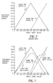
- FIG. 2 shows a plot of the perceived graininess as a function of the light and dark ink amounts for a typical inkjet printer.
- a larger value for the graininess indicates that the printed pattern of dots is more visible, and therefore more objectionable to the observer. As seen in FIG. 2, the graininess is larger when small combinations of light and dark ink are placed on the page.
- the perceived graininess of a pattern can be determined by many methods. One such method is to simply print a test image containing a variety of patterns and ask a panel of human observers to rate the graininess of each pattern. Another method is to compute the graininess from instrumented measurements of the patterns according to an equation.
- G ( C L , C D ) ⁇
- P is the frequency spectrum measured from a printed test patch containing light and dark ink amounts specified by C L and C D
- V(C L ,C D ) V L (C L )+V D (C D )
- V L (C L ) is the volume of light ink per unit area deposited on the page by the printer in response to the light ink control signal C L
- V D (C D ) is the volume of dark ink per unit area deposited on the page by the printer in response to the dark ink control signal C D
- FIG. 3 shows a plot of the total ink volume V as a function of the light and dark ink amounts for a typical printer. As seen from FIG.
- the volume increases as the printer places a higher fraction of each ink on the page.
- the less volume of ink that is used to reproduce an image the more generally desirable it is, due to the minimization of the aforementioned image artifacts associated with printing high volumes of ink.
- M ( C L , C D ) ⁇ G ( C L , C D ) + ⁇ V ( C L , C D ) where ⁇ and ⁇ are constants.
- This equation results in a metric function value for each combination of C L , C D . Larger values of the metric function indicate less desirable C L , C D combinations, and smaller values for the metric function indicate more desirable C L , C D combinations.
- the constants a and ⁇ are adjusted to indicate the relative importance of graininess and total ink volume to the particular inkjet printing application.
- the total ink volume may be more important than the graininess, and the constants might be chosen such that ⁇ > ⁇ .
- the constants might be chosen such that ⁇ > ⁇ . While the values of the constants ⁇ and ⁇ are important in determining the behavior of the printing system, it should be noted that the present invention will apply to any values chosen for ⁇ and ⁇ .
- FIG. 5 the contents of the look-up tables 30, 32 as disclosed by the method of Tajika and others are plotted.
- These look-up tables describe the cyan density tonescale of a system in which the light cyan ink is increased until it fully covers the page, and then the dark cyan ink is added until it fully covers the page while the light ink is simultaneously removed.
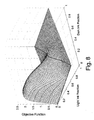
- these look-up tables define a path through the two dimensional C L , C D ink fraction space, and the value of the metric function M evaluated along this path is shown in FIG. 6. Note that the path cuts across a corner of the "hump" defined by the metric function, indicating the use of less desirable C L , C D ink combinations in the middle portion of the tonescale.
- the path defined by the prior art look-up tables of FIG. 5 clearly is not optimal, as poor image quality will result in the center portion of the tonescale, and too much ink will unnecessarily be used in other portions.
- the present invention describes a method of optimally deriving the look-up tables 30, 32, 34, 36 of FIG. 1 to overcome the non-optimal shortcomings of the prior art look-up tables.
- an objective function is created that accounts for the value of the metric function M along the entire tonescale path defined by the look-up tables.
- An example of such an objective function, M path is given by the following equation:
- This objective function is essentially the integral of the metric function along the path defined by the look-up tables LUT C,L and LUT C,D .
- One skilled in the art will recognize that other objective functions certainly exist that are suitable for use in the present invention.
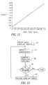
- the objective function is then used in a constrained minimization process as illustrated in the process flow diagram of FIG. 13, in which an initial set of look-up tables 60 are created, and a set of constraints 70 are applied to the look-up tables to produce candidate look-up tables.
- the objective function 80 is then computed for the candidate look-up tables, and compared to previous values of the objective function corresponding to previous candidate look-up tables. If the minimization process meets some termination criteria 90 (such as number of iterations, detection of the global minimum solution, and so forth), then the process terminates and the optimal look-up tables are created.
- the candidate look-up tables are perturbed 100 according to a set of rules governed by the particular minimization algorithm, and these look-up tables are fed back to the next iteration of the process.
- constrained minimization algorithms can be applied to the present invention, and that the optimal look-up tables derived will differ slightly depending on the particular algorithm chosen.
- FIG. 7 shows the optimized look-up tables with paths defined by the optimized look-up tables of FIG. 7 (shown as a dotted line) and the prior art look-up tables of FIG. 5, shown as a solid line.
- the optimized path avoids crossing the "hump" of the metric function in the central portion of the tonescale, indicating that better image quality will be obtained.
- the optimized path does not go all the way to full coverage of the light ink before it starts to use the dark ink.
- the optimized path bends around the contour of the metric function to minimize the total amount of ink used while maximizing the image quality. It should also be noted that since both paths start and end at the same point, then the dynamic range of the printer (D min , D max ) will be the same. For these reasons, the optimized look-up tables are advantaged relative to the prior art.
- a set of constraints 70 were applied.
- the types of constraints that can be applied and their effects on the optimal look-up tables will be discussed.
- One important constraint that controls the selection of the optimal solution is a density monotonicity constraint. This means that each point along the path specified by the optimal look-up tables must produce a density greater than the previous point. It is well known in the art that this is a desirable attribute of a printing system.
- FIG. 9 the density as a function of the light and dark ink amounts is shown, along with the prior art path (solid line) and the optimal path (dotted line). It can be seen from the curved nature of the density surface that it is possible to specify a path that violates the density monotonicity constraint, but both the prior art and optimal paths satisfy the constraint.
- a slightly stronger version of the density monotonicity constraint is the density derivative threshold constraint. This constraint simply means that the density must not only be monotonic, but that the density difference between any two adjacent points along the path must be greater than a non-zero threshold. This may be advantageous in certain printing systems where low slopes of the density tonescale can sometimes cause difficulties in calibrating the printer tonescale.
- Another constraint on the optimal path solution that may be advantageous when performing tonescale calibration is a density smoothness constraint.
- This constraint simply means that abrupt changes in the density derivative should be avoided. This corresponds to having look-up tables that define smooth, rounded paths, such as the optimal path shown in FIG. 9, and avoid sharp corners, such as are present in the prior art path of FIG. 9.
- An additional constraint that may be applied on the colorant amount is to constrain the relative amounts of the light and dark inks that are used.
- a printer system implementing optimal look-up tables may not use equal amounts of the light and dark ink. This may be disadvantageous if the ink supply cartridges for the light and dark inks are the same size. The user may end up replacing one cartridge much more often than the other, or even worse, if the two cartridges are bound together, the user may be forced to discard a cartridge that is partially full of one of the inks. Thus, it may be advantageous to constrain the look-up table optimization procedure so that a desired ratio of light and dark inks are used. The relative amount of light and dark inks may alternatively be considered as part of the objective function rather than a constraint.
- the objective function might become: where h(C) is the expected histogram of cyan printer code values, "abs" is the absolute value function, ⁇ and ⁇ are constants, and R is a desired light to dark ink usage ratio.
- the second term of the above equation represents the difference between the ratio of light ink usage to dark ink usage for the candidate look-up tables and the desired ratio. This is just one example of how the objective function may be modified to include a particular attribute. Other attributes may be desirable depending on the characteristics of the printer system, and could be added to the objective function as additional terms.
- the density tonescale In addition to density and/or colorant amounts as described above, it may also be desirable to specify the density tonescale to match some aim response.
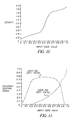
- the density tonescale that results from using the optimal look-up tables of FIG. 7 is shown in FIG. 10.
- the density tonescale satisfies the above mentioned constraints in that it is monotonic and smooth, but it is quite non-linear in nature, and is therefore an undesirable tonescale response for a printer.
- This is easily corrected for by simply resampling the optimal look-up tables of FIG. 7 to produce the resampled optimal look-up tables of FIG. 11.
- the resampling process was performed such that the density tonescale response of the printer would be linear, as shown in FIG. 12.
- the same procedure can be used to produce any desired tonescale aim, and this process will be easily performed by one skilled in the art.
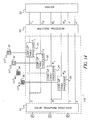
- FIG. 14 an advantageous use of the present invention within a modified color transform processor 110 is shown.
- This figure shows the same image processing block diagram of FIG. 1, with an additional dashed box showing a modified color transform processor 110.
- Many color transform file formats such as ICC profiles, allow for the specification of look-up tables to be appended to the color transform. This feature could be used to apply the look-up tables 30, 32, 34, 36 to the data.
- an ICC profile that encapsulates the look-up table processors 20, 22, 24, 26 could be built and combined with the ICC profile used by the color transform processor 10.
- the modified color transform processor 110 encapsulates the functionality of the color transform processor 10 with the look-up table processors 20, 22, 24, 26 to specify a single process that transforms the input RGB image code values to the colorant control signals ⁇ C L , C D , M L , M D , Y, K ⁇ . This arrangement has possible advantages in terms of computational speed, efficiency, and accuracy.
- a computer program can be used for performing steps of this invention. It can be provided on a computer readable storage medium.
- the computer readable storage medium may comprise, for example, magnetic storage media such as magnetic disk (for example, a floppy disk), or magnetic tape, optical storage medium such as optical disk, optical tape or machine readable barcode, solid state electronic storage devices such as random access memory (RAM), or read-only memory (ROM), or any other physical device or medium employed to store the program.
- the method wherin the look-up tables are formed subject to the constraint that the derivative of the total colorant amount of the reproduced image with respect to the input code value is larger than a threshold colorant amount derivative.
- look-up tables are formed subject to the constraint that the colorant amount varies smoothly with input code value.
- look-up tables are formed subject to the constraint that the density of the reproduced image varies smoothly with input code value.
- the method further including at least one color channel which does not correspond to multiple colorants having substantially the same color.
- the digital printer is an inkjet printer.
- the method wherein the colorant control signal controls the colorant amount by controlling the number of drops of colorant printed at each pixel.
- the method wherein the colorant control signal controls the local average colorant amount using a halftoning method to determine whether or not colorant should be printed at each pixel.
- the method wherein the colorant control signal controls the local average colorant amount using a multi-level halftoning method to determine which of a set of possible colorant amounts should be printed at each pixel.
Landscapes
- Physics & Mathematics (AREA)
- Discrete Mathematics (AREA)
- General Physics & Mathematics (AREA)
- Engineering & Computer Science (AREA)
- Multimedia (AREA)
- Signal Processing (AREA)
- Ink Jet (AREA)
- Color, Gradation (AREA)
- Color Image Communication Systems (AREA)
- Fax Reproducing Arrangements (AREA)
- Particle Formation And Scattering Control In Inkjet Printers (AREA)
Applications Claiming Priority (2)
| Application Number | Priority Date | Filing Date | Title |
|---|---|---|---|
| US455981 | 1999-12-06 | ||
| US09/455,981 US6312101B1 (en) | 1999-12-06 | 1999-12-06 | Method of printing digital images using multiple colorants having substantially the same color |
Publications (2)
| Publication Number | Publication Date |
|---|---|
| EP1107575A2 true EP1107575A2 (fr) | 2001-06-13 |
| EP1107575A3 EP1107575A3 (fr) | 2004-03-24 |
Family
ID=23810976
Family Applications (1)
| Application Number | Title | Priority Date | Filing Date |
|---|---|---|---|
| EP00204192A Withdrawn EP1107575A3 (fr) | 1999-12-06 | 2000-11-24 | Procédé d'impression d'images numériques avec plusieurs colorants avec substantiellement la même couleur |
Country Status (3)
| Country | Link |
|---|---|
| US (1) | US6312101B1 (fr) |
| EP (1) | EP1107575A3 (fr) |
| JP (1) | JP2001213009A (fr) |
Cited By (4)
| Publication number | Priority date | Publication date | Assignee | Title |
|---|---|---|---|---|
| EP1289262A1 (fr) | 2001-08-20 | 2003-03-05 | Eastman Kodak Company | Procédé pour l'impression en couleurs multiples d'images numériques utilisant une quantité réduite d'encre |
| EP1478170A1 (fr) * | 2003-05-14 | 2004-11-17 | Agfa-Gevaert | Système et procédé pour calibrer un dispositif d'impression ayant des encres légères et lourdes |
| EP1447972A3 (fr) * | 2002-12-04 | 2008-03-19 | Eastman Kodak Company | Calibrage d'une imprimante digitale utilisant une fonction de coût |
| WO2015078827A1 (fr) * | 2013-11-29 | 2015-06-04 | Agfa Graphics Nv | Procédé de séparation de colorants |
Families Citing this family (14)
| Publication number | Priority date | Publication date | Assignee | Title |
|---|---|---|---|---|
| US7057756B2 (en) * | 2000-07-17 | 2006-06-06 | Canon Kabushiki Kaisha | Image processor, method for processing image, printing apparatus, printing method, program, and storage medium that stores computer-readable program code |
| US7190485B2 (en) * | 2001-06-14 | 2007-03-13 | Eastman Kodak Company | Method for multilevel printing of digital images using reduced colorant amounts |
| US6588879B2 (en) * | 2001-12-03 | 2003-07-08 | Supersample Corporation | Method for ink jet printing a digital image on a textile, the system and apparatus for practicing the method, and products produced by the system and apparatus using the method |
| JP2003170617A (ja) * | 2001-12-07 | 2003-06-17 | Brother Ind Ltd | 分配カーブ生成装置及び分配カーブ生成プログラム |
| JP3991677B2 (ja) * | 2001-12-26 | 2007-10-17 | コニカミノルタビジネステクノロジーズ株式会社 | プロファイルを作成するプログラム、および、プロファイル作成システム |
| US20040085553A1 (en) * | 2002-10-30 | 2004-05-06 | Eastman Kodak Company | Multitoning a digital image having at least one group of similar colors channels |
| US7239422B2 (en) * | 2002-12-04 | 2007-07-03 | Eastman Kodak Company | Color gamut mapping using a cost function |
| US7283282B2 (en) * | 2003-01-31 | 2007-10-16 | Eastman Kodak Company | Method of adjusting color in a color proof |
| US7365879B2 (en) * | 2004-05-13 | 2008-04-29 | Eastman Kodak Company | Determining sets of n-dimensional colorant control signals |
| US8085436B2 (en) * | 2008-12-09 | 2011-12-27 | Eastman Kodak Company | Digital printing using similar colorants |
| JP5712684B2 (ja) * | 2011-03-07 | 2015-05-07 | 富士ゼロックス株式会社 | 色処理装置及びプログラム |
| JP6149614B2 (ja) * | 2013-08-30 | 2017-06-21 | セイコーエプソン株式会社 | 記録データ生成装置、プログラム、記録データ生成方法及び記録装置 |
| US10118436B2 (en) | 2015-01-26 | 2018-11-06 | Crayola, Llc | Pixel art crayon and marker photo array assembly and kit |
| US10471617B2 (en) | 2015-01-26 | 2019-11-12 | Crayola Llc | Pixel art crayon and marker photo array assembly and kit |
Citations (1)
| Publication number | Priority date | Publication date | Assignee | Title |
|---|---|---|---|---|
| US5878195A (en) * | 1995-09-15 | 1999-03-02 | Agfa-Gevaert N.V. | Color separation method and apparatus for same |
Family Cites Families (11)
| Publication number | Priority date | Publication date | Assignee | Title |
|---|---|---|---|---|
| DE3326557A1 (de) | 1982-07-23 | 1984-01-26 | Canon K.K., Tokyo | Verfahren und einrichtung zur bilderzeugung |
| JPS5941970A (ja) | 1982-09-01 | 1984-03-08 | Canon Inc | 画像形成方法及び装置 |
| US4635078A (en) * | 1983-04-28 | 1987-01-06 | Canon Kabushiki Kaisha | Intermediate gradient image producing method |
| US4672432A (en) | 1983-04-28 | 1987-06-09 | Canon Kabushiki Kaisha | Method for recording a color image using dots of colorants of different densities |
| JP2859296B2 (ja) | 1989-06-01 | 1999-02-17 | キヤノン株式会社 | 画像再生方法及びその装置 |
| JP2991572B2 (ja) * | 1991-09-11 | 1999-12-20 | キヤノン株式会社 | 画像記録装置 |
| JPH06340094A (ja) * | 1993-05-31 | 1994-12-13 | Canon Inc | インクジェット記録装置およびインクジェット記録方法 |
| US6142599A (en) * | 1995-06-29 | 2000-11-07 | Canon Kabushiki Kaisha | Method for ink-jet recording and an ink-jet recording apparatus |
| US5795082A (en) * | 1996-06-27 | 1998-08-18 | Seiko Epson Corporation | Printing system utilizing inks of different densities, cartridge used therefor, and method of recording images |
| JP3209402B2 (ja) * | 1996-11-01 | 2001-09-17 | 富士ゼロックス株式会社 | 画像処理装置 |
| JPH10211693A (ja) * | 1997-01-31 | 1998-08-11 | Canon Inc | プリント装置およびプリント方法 |
-
1999
- 1999-12-06 US US09/455,981 patent/US6312101B1/en not_active Expired - Lifetime
-
2000
- 2000-11-24 EP EP00204192A patent/EP1107575A3/fr not_active Withdrawn
- 2000-12-04 JP JP2000368118A patent/JP2001213009A/ja not_active Withdrawn
Patent Citations (1)
| Publication number | Priority date | Publication date | Assignee | Title |
|---|---|---|---|---|
| US5878195A (en) * | 1995-09-15 | 1999-03-02 | Agfa-Gevaert N.V. | Color separation method and apparatus for same |
Cited By (5)
| Publication number | Priority date | Publication date | Assignee | Title |
|---|---|---|---|---|
| EP1289262A1 (fr) | 2001-08-20 | 2003-03-05 | Eastman Kodak Company | Procédé pour l'impression en couleurs multiples d'images numériques utilisant une quantité réduite d'encre |
| EP1447972A3 (fr) * | 2002-12-04 | 2008-03-19 | Eastman Kodak Company | Calibrage d'une imprimante digitale utilisant une fonction de coût |
| EP1478170A1 (fr) * | 2003-05-14 | 2004-11-17 | Agfa-Gevaert | Système et procédé pour calibrer un dispositif d'impression ayant des encres légères et lourdes |
| WO2015078827A1 (fr) * | 2013-11-29 | 2015-06-04 | Agfa Graphics Nv | Procédé de séparation de colorants |
| US10097727B2 (en) | 2013-11-29 | 2018-10-09 | Agfa Nv | Colorant splitting method |
Also Published As
| Publication number | Publication date |
|---|---|
| EP1107575A3 (fr) | 2004-03-24 |
| JP2001213009A (ja) | 2001-08-07 |
| US6312101B1 (en) | 2001-11-06 |
Similar Documents
| Publication | Publication Date | Title |
|---|---|---|
| US6312101B1 (en) | Method of printing digital images using multiple colorants having substantially the same color | |
| JP4143359B2 (ja) | 顔料量を計算する方法および入力画像を修正するための方法 | |
| EP1427184A2 (fr) | Conversion de gamme de couleurs utilsant une fonction de coût | |
| EP1267565B1 (fr) | Méthode pour l'impression à niveaux multiples d'images numériques utilisant des quantités réduites de colorants | |
| US7245395B2 (en) | Calibrating a digital printer using a cost function | |
| US8373898B2 (en) | Method, apparatus and computer program for transforming digital color images | |
| EP1437678B1 (fr) | Traitement de réduction d'encre colorimétrique pour imprimantes | |
| JP6193594B2 (ja) | 画像処理装置、画像処理方法、画像処理システムおよびプログラム | |
| JP3689458B2 (ja) | 画像処理装置及び方法 | |
| US9162450B2 (en) | Image processing apparatus and image processing method | |
| US8149464B2 (en) | Clustered dot-screen design method, a device to perform the clustered dot-screen design method based on human vision and printer model characteristics, and an image-forming apparatus to output binary images on a designed screen | |
| US8098403B2 (en) | Color error diffusion with error signal offset | |
| US7652795B2 (en) | Reducing ink bleed artifacts | |
| EP1398162B1 (fr) | Calibration d'un procédé d'impression à jet d'encre à teintes multiples | |
| US8422082B2 (en) | Reducing ink bleed artifacts for RGB images | |
| US8085436B2 (en) | Digital printing using similar colorants | |
| US6554385B2 (en) | Color image generation apparatus and color image generation method | |
| US11936835B2 (en) | Image processing apparatus, image processing method, and storage medium which reduce a color difference and a frequency difference between two images | |
| US8854690B2 (en) | Creation method of total color material amount restriction table, and recording medium | |
| US7564589B2 (en) | Color error diffusion with error signal offsets | |
| US20030081230A1 (en) | Delayed decision dot placement for plane-dependent CMYK error diffusion | |
| US20050122546A1 (en) | Image processing mechanism for image enhancement and halftone processing | |
| JP4408773B2 (ja) | 色処理装置および色処理方法 |
Legal Events
| Date | Code | Title | Description |
|---|---|---|---|
| PUAI | Public reference made under article 153(3) epc to a published international application that has entered the european phase |
Free format text: ORIGINAL CODE: 0009012 |
|
| AK | Designated contracting states |
Kind code of ref document: A2 Designated state(s): AT BE CH CY DE DK ES FI FR GB GR IE IT LI LU MC NL PT SE TR |
|
| AX | Request for extension of the european patent |
Free format text: AL;LT;LV;MK;RO;SI |
|
| PUAL | Search report despatched |
Free format text: ORIGINAL CODE: 0009013 |
|
| AK | Designated contracting states |
Kind code of ref document: A3 Designated state(s): AT BE CH CY DE DK ES FI FR GB GR IE IT LI LU MC NL PT SE TR |
|
| AX | Request for extension of the european patent |
Extension state: AL LT LV MK RO SI |
|
| 17P | Request for examination filed |
Effective date: 20040901 |
|
| AKX | Designation fees paid |
Designated state(s): DE FR GB |
|
| 17Q | First examination report despatched |
Effective date: 20041118 |
|
| STAA | Information on the status of an ep patent application or granted ep patent |
Free format text: STATUS: THE APPLICATION IS DEEMED TO BE WITHDRAWN |
|
| 18D | Application deemed to be withdrawn |
Effective date: 20080131 |