EP1107607A2 - JPEG Kompressionsverfahren - Google Patents
JPEG Kompressionsverfahren Download PDFInfo
- Publication number
- EP1107607A2 EP1107607A2 EP00126725A EP00126725A EP1107607A2 EP 1107607 A2 EP1107607 A2 EP 1107607A2 EP 00126725 A EP00126725 A EP 00126725A EP 00126725 A EP00126725 A EP 00126725A EP 1107607 A2 EP1107607 A2 EP 1107607A2
- Authority
- EP
- European Patent Office
- Prior art keywords
- transform
- data
- image data
- block
- image
- Prior art date
- Legal status (The legal status is an assumption and is not a legal conclusion. Google has not performed a legal analysis and makes no representation as to the accuracy of the status listed.)
- Withdrawn
Links
Images



Classifications
-
- H—ELECTRICITY
- H04—ELECTRIC COMMUNICATION TECHNIQUE
- H04N—PICTORIAL COMMUNICATION, e.g. TELEVISION
- H04N19/00—Methods or arrangements for coding, decoding, compressing or decompressing digital video signals
- H04N19/10—Methods or arrangements for coding, decoding, compressing or decompressing digital video signals using adaptive coding
- H04N19/102—Methods or arrangements for coding, decoding, compressing or decompressing digital video signals using adaptive coding characterised by the element, parameter or selection affected or controlled by the adaptive coding
- H04N19/124—Quantisation
- H04N19/126—Details of normalisation or weighting functions, e.g. normalisation matrices or variable uniform quantisers
-
- H—ELECTRICITY
- H04—ELECTRIC COMMUNICATION TECHNIQUE
- H04N—PICTORIAL COMMUNICATION, e.g. TELEVISION
- H04N19/00—Methods or arrangements for coding, decoding, compressing or decompressing digital video signals
- H04N19/60—Methods or arrangements for coding, decoding, compressing or decompressing digital video signals using transform coding
Definitions
- JPEG Joint Photographic Experts Group
- JPEG uses the discrete cosine transform (DCT) to map space data into spatial frequency domain data.
- DCT discrete cosine transform
- the first step in JPEG compression is to transform an 8 x 8 block of pixels into a set of 8 x 8 coefficients using the DCT.
- the DCT with the lowest frequency is referred to as the DC coefficient (DCC), and the remaining coefficients are AC coefficients (ACCs).
- DCC and ACCs are quantized -- divided by an integer referred to as the "step size" and rounded to the nearest whole number.
- step size an integer referred to as the "step size” and rounded to the nearest whole number.
- the losses that occur during JPEG compression typically occur during the quantization step. The magnitude of this loss is obviously dependent upon the step size selected and the resulting amount of round-off required to perform quantization.
- the quantized coefficients are arranged in a one dimensional vector by following a selected path (i.e. zigzag) through the 8 x 8 block of quantized coefficients.
- the DCC is typically the first value in the vector.
- Ordinary JPEG compression typically includes replacing the quantized DCC with the difference of its actual value minus the DCC of the previous block, to provide a differential DCC.
- the vector is encoded into a bit stream through a sequence of Run Length Counting (RLC) operations, combined with Variable Length Codes (VLC) to produce a compressed data stream.
- RLC Run Length Counting
- VLC Variable Length Codes
- Fax transmission of color image data is often accomplished by scanning the image at the sending fax to generate digital color image data, subjecting this digital color image data to JPEG compression and then transmitting the compressed digital color image data over telephone lines to the receiving fax. Since color image data is so complex, high compression ratios must usually be applied in order to complete the transmission within an acceptable time frame. High compression ratios lead to more data loss, which typically occurs at the higher end of the frequency range. Further, the imaging devices typically included with fax machines in the lower end of the market usually include thermal ink-jet printers and would likely use error diffusion halftoning techniques. The halftoning that occurs when using a thermal ink jet printer results in an additional loss of high frequency data. Thus, much of the detail in the original image that is preserved and transmitted will never actually be viewed by the ultimate user.
- the "sending" portion of fax transmission includes scanning the original image, generation of a corresponding digital image, and any one of a number of data reduction techniques, most notably some form of data compression. Once these steps are completed, the compressed data is transmitted serially to the receiving fax in a bit stream.
- the length of the bit stream used to describe the image is inversely proportional to the amount of compression that has been applied. Thus, if the compression ratio is large the length of the bit stream used to describe the image will be very short, resulting in a substantial reduction in the transmission time for the data stream.
- US-A 5,737,450 to Hajjahmad et al. issued April 7, 1998 discloses a method and apparatus for applying an image filter to an image signal where image data terms, corresponding to the image signal, are converted by means of an overlapping operation and a scaled forward orthogonal transformation to form frequency coefficient matrices, the image filter is converted by means of a descaled orthogonal transformation to form a descaled frequency filter matrix, and the frequency coefficient matrices are multiplied by the descaled frequency filter matrix to form filtered coefficient matrices for conversion into a filtered image signal by means of an inverse orthogonal transformation process.
- US-A 5,699,170 to Yokose et al. issued December 16, 1997 discloses an image communication system wherein transmission of an image between an image transmission apparatus and an image reception apparatus which include image output sections having different performances can be performed without making an inquiry for the performance prior to transmission is disclosed.
- An image is inputted by an image input section and sent to a hierarchization section in the image transmission apparatus.
- the hierarchization section converts the inputted image into hierarchic communication data and transmits hierarchized data to a selection section of the image reception apparatus.
- the selection section extracts only necessary data from the hierarchic communication data transmitted thereto in accordance with the performance of an image output section of the image reception section and then sends the necessary data to the image output section after, if necessary, they are converted into image data.
- the image output section visualize the image data transmitted thereto from the selection section.
- the present invention relates to a method of improving the speed and efficiency of electronic data compression.
- the method comprises obtaining input image data which includes discrete values that represent light intensity in an image. Then applying a first transform to the input image data to produce a first transform result. This is followed by comparing the first transform result to a threshold. Finally, a either second transform is applied to the first transform result, or the substitution of a zero value for the first transform result is used to generate approximation data.
- a method of transmitting a facsimile of an original image from a sending location to a receiving location comprises acquiring the original image and generating digital image data therefrom, wherein the digital image data includes pixel values which represent the light intensity cf the original image. Then applying a first transform to the input image data to produce a first transform result. This is followed by comparing the first transform result to a threshold. Then in generating approximation data which provides an estimated value of image light intensity, either a second transform is applied to the first transform result, or a zero value is substituted for the first transform result. Finally the output image data is derived from the approximation data.
- FIGURE 1 is a generalized block diagram illustrating general aspects of a facsimile machine that may be used to practice the present invention.
- FIGURE 2 contains a schematic illustration of the steps used to carry out a JPEG compression scheme.
- FIGURE 3 is a detailed illustration of an example of a labeling configuration of an 8 x 8 block of pixels.
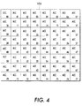
- FIGURE 4 contains a detailed illustration of the labeling configuration of DCT coefficients obtained by application of a discrete cosine transformation to the 8 x 8 block of pixels illustrated in FIG. 3.
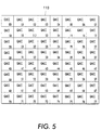
- FIGURE 5 illustrates one example of the manner in which the DCT coefficients of FIG. 4 may be labeled after quantization.
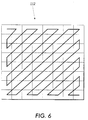
- FIGURE 6 depicts a "zig zag" pattern, one embodiment of the manner in which quantized pixels may be selected for placement into a one dimensional vector.
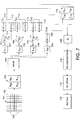
- FIGURE 7 contains a schematic illustration of one way the present invention may be implemented in a JPEG compression technique.
- FIGURE 8 shows a quantization table and derived threshold table.
- the present invention is directed to a method and apparatus for compressing complex digital image data to enhance the efficiency of data transmission.
- FIG. 1 is a block diagram showing structure of an embodiment of a facsimile (fax) apparatus 10 according to the present invention.
- Fax 10 includes a CPU 12 for executing controlling processes and facsimile transmission control procedures, a RAM 14 for controlling programs and a display console 16 with various buttons and/or switches for controlling the facsimile apparatus and LCDs or LED's for reviewing the status of system operation.
- a scanner 20 is also included for acquiring an original image and generating image data therefrom.
- Image processing unit 22 is included to perform encoding and decoding (compression and decompression) processes between an image signal and transmitted codes.
- fax 10 includes or interfaces with a modem 24, which is a modulating and demodulating device that transmits and receives picture information over telephone lines to a compatible receiving device 26, such as another facsimile machine, a printer, computer terminal or similar apparatus.
- modem 24 is a modulating and demodulating device that transmits and receives picture information over telephone lines to a compatible receiving device 26, such as another facsimile machine, a printer, computer terminal or similar apparatus.
- image processing unit 22 is used to compress and decompress image signals and transmitted codes.
- One common method of compressing and decompressing image signals is through use of the JPEG (Joint Photographic Experts Group) standard described in detail with reference to FIG. 2.
- JPEG Joint Photographic Experts Group
- An original image is scanned by fax 10 to generate a corresponding digital image.
- the digital image is separated into 8 x 8 blocks 102 of picture elements 120 or "pixels" which indicate the intensity of the light that is measured at discrete intervals throughout the surface of the page. For example, a spot that is covered with black ink will not reflect any light. The value of the pixel 120 will typically be 0 at that location. On the other hand, a spot that is completely uncovered by ink will reflect the color of the page on which the image resides.
- the measured light intensity of the pixel 120 would be 1 at that spot.
- Gray areas such as those which represent color or black and white halftoned areas of the image would register a light intensity somewhere between 0 and 1.
- the values of the pixels 120 in block 102 are transformed through DCT into a set 106 of 8 x 8 coefficients as indicated in step 104.
- the DCT coefficient with the lowest frequency is referred to as the DC coefficient (DCC), and the remaining coefficients are AC coefficients (ACCs).
- the DCC and ACCs are quantized -- each coefficient is divided by a predetermined whole number referred to as the "step size" at step 108 and then a selected pattern (usually a "zigzag") is followed through the 8 x 8 block of quantized coefficients 110 as indicated in step 112 to place the coefficients in a desired order in a one dimensional vector 114.
- the quantized DCC is typically the first value of the vector 114, and is represented differentially as the actual DCC value minus the DCC of the previous block as shown in block 116.
- Vector 114 is encoded into a bit stream through a sequence of Run Length Counting (RLC) operations which count the number of zero ACCs that reside in the path before a non-zero ACC.
- RLC Run Length Counting
- VLC Variable Length Codes
- FIG. 3 contains a detailed illustration of an 8 x 8 block of pixels 120 and the labeling configuration that will be used throughout the description of the present invention. It should be noted here that pixels 120 and pixel blocks 102 can be labeled in numerous other ways and it is not intended to imply that either JPEG compression or the present invention are limited to the ordering scheme shown here. Similarly, FIGS. 4 and 5 contain detailed illustrations of the unquantized and quantized DCT coefficients respectively that correspond to the 8 x 8 block 102 of pixels 120 illustrated in FIG. 3. Again, neither standard JPEG compression or the present invention are limited to these embodiments.
- FIG. 6 contains a detailed illustration of one pattern 112 in which the quantized DCT coefficients may be selected for placement into one dimensional vector 114.
- the illustration shown in FIG. 6 merely shows one of many possible zigzag coefficient selection patterns 112 that may be followed in order to practice the present invention.
- the present invention includes performing a portion of the JPEG compression method on a reduced set of data, without producing a substantial loss in the quality of the output image.
- the invention takes advantage of the fact that a 4-point DCT can be performed more quickly than an 8-point DCT can.
- JPEG achieves compression because most DCT coefficients in a block after quantization are zero.
- the present invention saves time by not computing zero coefficients. It is also known that a certain amount of high frequency loss can be tolerated particularly with color separation data or in a fax environment.
- the invention identifies and examines high band pass information for activity. Low activity blocks below a threshold as identified by the invention need not have a DCT coefficient calculated. Instead a zero value is substituted. This also allows the invention to save computation time.
- the scanned image is separated into blocks 701 of pixels 120 which indicate the intensity of the light at the various locations of the image.
- an 8 x 8 block of pixels has shown to be very successful when used with the present invention.
- other pixel block dimensions are possible and the invention is not limited to this embodiment.
- a smaller or larger block size might be chosen when it is desired to preserve more or less image detail.
- horizontal and vertical dimensions are identical in the embodiment of pixel block 701 described here, this is not a requirement for practicing the present invention.
- a non-square block might be chosen if the image was generated for a device possessing asymmetric resolutions in the vertical and horizontal directions.
- block 701 must be segmented into sub-blocks 700 as indicated in Figure 7.
- an 8 x 8 block of pixels is used to practice the invention, segmenting pixel block 701 into 4 sub-blocks 700, where each sub-block 700 is an array having four pixels 120 in the horizontal direction and four pixels 120 in the vertical direction.
- each sub-block 700 is an array having four pixels 120 in the horizontal direction and four pixels 120 in the vertical direction.
- each of the above described sub-blocks 700 shown in block 701 are labeled in block 702.
- Each illustrated sub-block 700 is now represented as B 00 , B 01 , B 10 , and B 11 in block 702.
- a Haar transform 703 is performed upon the data in block 702.
- a Haar transform is a technique well understood in the art as performing a matrix sum and difference operation.
- the Haar transform provides quadrant results A 00 , A 01 , A 10 , A 11 in the 8 x 8 quadrant blocks 704, 705, 706, and 707, respectively.
- Using the 4 x 4 Haar transform operation here separates out low pass band and high pass band components for subsequent operation.
- the A 00 result provides the low pass band information. Because low pass band information is essential for successful reconstruction of an image, the A 00 result is subsequently transformed by a 4-point DCT operation 708.
- the A 01 , A 10 , A 11 quadrant results constitute higher frequency or high pass band information. Therefore, for quadrant results A 01 , A 10 , A 11 as found in quadrant blocks 709, 710, and 711 respectively, a comparison is made to a threshold value T 01 , T 10 , T 11 respectively. The comparison of the quadrant results to a threshold is provided for in decision blocks 709, 710, and 711.
- Threshold table 802 as found in Figure 8 and described below, is utilized for supplying the threshold values used in the decision blocks 709, 710, and 711. If a given high pass band quadrant result is found to be above a particular threshold value, it is deemed as having enough information to warrant 4-point DCT transformation at DCT-4 block 712, 713 and 714 respectively. However, as will often happen in a preferred embodiment, when a high pass quadrant result is found to be below the threshold value, that result is small enough to discard. In that event a zero is substituted as shown in Figure 7 by the "Set to zero" blocks 715, 716 and 717. This provides the advantage of saving the 4-point DCT computational time which in a preferred embodiment constitutes picture detail information which is of little or even no consequence for a given targeted receiving device 26.
- the 4-point DCT must be scaled so that when C 00 , C 01 , C 10 , and C 11 are combined in approximation block 718, the coefficients are compatible with the coefficients which would be obtained from an 8-point DCT. Therefore, the 4-point DCT is defined as: DCT4( U ) ⁇ 1 2 D 4 UD T 4 .
- FIG. 8 Provided in Figure 8 is a preferred embodiment quantization table 800.
- this table 800 is but one of many possibilities. It is provided as an example, and as an aid for the explanation of the origin of a preferred embodiment threshold table 802.
- the values found in threshold table 802 may be developed in many ways. However, for a preferred embodiment threshold table 802 is derived from quantization table 800. To do this an average of the values by quadrant in the quantization table 800 is made to arrive at the values found in the threshold table 802. Because there is no comparison made for A00, an "X" is shown as the value for that quadrant.
- the values shown "44", "44", and “108” are the thresholds for comparison to A 01 , A 10 and A 11 respectively, and as stated above are averages from quantization table 800.
- step 112 a "zigzag" is followed through the 8 x 8 block of quantized coefficients resulting from step 108 to place the coefficients in a desired order in a one dimensional vector 114.
- the quantized DCC is typically the first value of the vector 114, and is represented differentially as the actual DCC value minus the DCC of the previous block as performed in block 116.
- Vector 114 is encoded into a bit stream through a sequence of Run Length Counting (RLC) operations which count the number of zero ACCs that reside in the path before a non-zero ACC.
- RLC Run Length Counting
- VLC Variable Length Codes
- a preferred embodiment as described above utilizing Haar transformation and 4-point DCT is exemplary for the greater processing speed it realizes by reducing the total processing complexity.
- Counting addition's, multiplication's, compares (to zero), shifts, etc. as one operation (op) the total complexity for the 8x8 2D DCT is 768 ops assuming separable fast algorithms.
- the complexity is 112 ops.
- the total complexity for the proposed transform is 336+112n ops, where n is the number of active high-frequency bands (0,1,2,3), i.e. bands above the threshold.
- the average complexity per block is 336+112 n , where n is the average value of n.
- the complexity is less than half of that of the DCT and in the worst case it is at least 12.5% less that the DCT.
- the transmitted data may convey the kind of transform which has been used.
- the digital image data may be output standard JPEG decoder.
- the receiving device may include a computer
- the receiving device can be used to convey to the output device that a transform has been used, and the output device is provided with a smart de-compressor with a inverse transform which is uses for outputting the digital image data.
Landscapes
- Engineering & Computer Science (AREA)
- Multimedia (AREA)
- Signal Processing (AREA)
- Compression Or Coding Systems Of Tv Signals (AREA)
- Compression Of Band Width Or Redundancy In Fax (AREA)
- Compression, Expansion, Code Conversion, And Decoders (AREA)
Applications Claiming Priority (2)
| Application Number | Priority Date | Filing Date | Title |
|---|---|---|---|
| US458855 | 1989-12-29 | ||
| US09/458,855 US6611626B1 (en) | 1999-12-10 | 1999-12-10 | Method of compressing JPEG files using a conditional transform |
Publications (2)
| Publication Number | Publication Date |
|---|---|
| EP1107607A2 true EP1107607A2 (de) | 2001-06-13 |
| EP1107607A3 EP1107607A3 (de) | 2004-04-21 |
Family
ID=23822365
Family Applications (1)
| Application Number | Title | Priority Date | Filing Date |
|---|---|---|---|
| EP00126725A Withdrawn EP1107607A3 (de) | 1999-12-10 | 2000-12-05 | JPEG Kompressionsverfahren |
Country Status (5)
| Country | Link |
|---|---|
| US (1) | US6611626B1 (de) |
| EP (1) | EP1107607A3 (de) |
| JP (1) | JP4809525B2 (de) |
| BR (1) | BR0006378A (de) |
| CA (1) | CA2325266C (de) |
Families Citing this family (4)
| Publication number | Priority date | Publication date | Assignee | Title |
|---|---|---|---|---|
| JP2002271613A (ja) * | 2001-03-09 | 2002-09-20 | Sharp Corp | 情報端末装置 |
| US7369706B2 (en) * | 2003-01-06 | 2008-05-06 | Matsushita Electric Industrial Co., Ltd. | Image-data processing device, image-data processing method, image-data distributing device and image-data transmitting system |
| US8170101B2 (en) * | 2006-10-27 | 2012-05-01 | Sharp Laboratories Of America, Inc. | Methods and systems for low-complexity data compression |
| WO2011016247A1 (ja) * | 2009-08-06 | 2011-02-10 | パナソニック株式会社 | 符号化方法、復号方法、符号化装置及び復号装置 |
Family Cites Families (12)
| Publication number | Priority date | Publication date | Assignee | Title |
|---|---|---|---|---|
| US4943855A (en) * | 1988-07-22 | 1990-07-24 | At&T Bell Laboratories | Progressive sub-band image coding system |
| JPH02198274A (ja) * | 1988-10-14 | 1990-08-06 | Fuji Photo Film Co Ltd | 画像データ圧縮記録装置 |
| DE69133412T2 (de) | 1990-09-04 | 2005-09-22 | Canon K.K. | Verfahren und Vorrichtung zur Bildverarbeitung |
| US5539836A (en) | 1991-12-20 | 1996-07-23 | Alaris Inc. | Method and apparatus for the realization of two-dimensional discrete cosine transform for an 8*8 image fragment |
| JPH0766913A (ja) | 1993-08-24 | 1995-03-10 | Fuji Xerox Co Ltd | 画像通信装置 |
| US5495292A (en) * | 1993-09-03 | 1996-02-27 | Gte Laboratories Incorporated | Inter-frame wavelet transform coder for color video compression |
| US5610657A (en) * | 1993-09-14 | 1997-03-11 | Envistech Inc. | Video compression using an iterative error data coding method |
| IL107658A0 (en) * | 1993-11-18 | 1994-07-31 | State Of Israel Ministy Of Def | A system for compaction and reconstruction of wavelet data |
| US6356663B1 (en) * | 1994-09-09 | 2002-03-12 | Intel Corporation | Processing image signals using spatial decomposition |
| US5737450A (en) | 1995-05-15 | 1998-04-07 | Polaroid Corporation | Method and apparatus for fast two-dimensional cosine transform filtering |
| US5867598A (en) | 1996-09-26 | 1999-02-02 | Xerox Corporation | Method and apparatus for processing of a JPEG compressed image |
| CN1369175A (zh) * | 1998-05-07 | 2002-09-11 | 萨尔诺夫公司 | 增加信息流解码器中存储器资源利用的方法及设备 |
-
1999
- 1999-12-10 US US09/458,855 patent/US6611626B1/en not_active Expired - Lifetime
-
2000
- 2000-11-08 CA CA002325266A patent/CA2325266C/en not_active Expired - Fee Related
- 2000-12-01 JP JP2000367120A patent/JP4809525B2/ja not_active Expired - Fee Related
- 2000-12-05 EP EP00126725A patent/EP1107607A3/de not_active Withdrawn
- 2000-12-11 BR BR0006378-9A patent/BR0006378A/pt not_active IP Right Cessation
Non-Patent Citations (1)
| Title |
|---|
| None * |
Also Published As
| Publication number | Publication date |
|---|---|
| US6611626B1 (en) | 2003-08-26 |
| BR0006378A (pt) | 2001-07-24 |
| JP2001218063A (ja) | 2001-08-10 |
| EP1107607A3 (de) | 2004-04-21 |
| JP4809525B2 (ja) | 2011-11-09 |
| CA2325266A1 (en) | 2001-06-10 |
| CA2325266C (en) | 2004-05-04 |
Similar Documents
| Publication | Publication Date | Title |
|---|---|---|
| JP3703195B2 (ja) | カラー画像伝送装置 | |
| US5883979A (en) | Method for selecting JPEG quantization tables for low bandwidth applications | |
| JP3005007B2 (ja) | 画像符号化装置 | |
| US6665444B1 (en) | Image processing apparatus and method, and storage medium | |
| EP0833519B1 (de) | Segmentierung und Hintergrundunterdrückung in JPEG-komprimierten Bildern mit Anwendung von Kodierungskostendaten | |
| EP1139290A2 (de) | Bildverarbeitungsvorrichtung und -verfahren | |
| EP1001607B1 (de) | Verfahren und Vorrichtung zur Analyse von Bilddaten um mehrere Umwandlungen für verbesserte Bilddatenübertragung durchzuführen | |
| US5911007A (en) | Image processing method and apparatus | |
| JP4083934B2 (ja) | 画像処理装置および画像処理方法 | |
| US20050030569A1 (en) | Image processing apparatus | |
| US6577772B1 (en) | Pipelined discrete cosine transform apparatus | |
| US6611626B1 (en) | Method of compressing JPEG files using a conditional transform | |
| JPH11187401A (ja) | 映像信号符号化装置 | |
| US6778707B1 (en) | Method for decompressing JPEG files using a variable block size inverse discrete cosine transform | |
| JP4486847B2 (ja) | 圧縮画像から中間調画像を作成する方法と装置 | |
| US6167153A (en) | Method of compressing JPEG files | |
| JP3718583B2 (ja) | 画像処理装置および画像処理方法 | |
| US6798543B1 (en) | Method and apparatus for compression and decompression of halftoned images | |
| US6771393B1 (en) | Transmission rate control for continuous-tone facsimile | |
| JP3733225B2 (ja) | 画像処理装置及び方法 | |
| EP0997847A2 (de) | Bilddatenkompressionsvorrichtung und -verfahren | |
| JPH06253121A (ja) | 画像伝送システムの画像処理方法 | |
| EP1489830B1 (de) | Verfahren und Vorrichtung für das Erzeugen eines halbtongerasterten Bildes von einem komprimierten Bild | |
| EP0997848A2 (de) | Bilddatenkompressionsvorrichtung | |
| JP2001197498A (ja) | 画像処理装置及び方法及び記憶媒体 |
Legal Events
| Date | Code | Title | Description |
|---|---|---|---|
| PUAI | Public reference made under article 153(3) epc to a published international application that has entered the european phase |
Free format text: ORIGINAL CODE: 0009012 |
|
| AK | Designated contracting states |
Kind code of ref document: A2 Designated state(s): AT BE CH CY DE DK ES FI FR GB GR IE IT LI LU MC NL PT SE TR |
|
| AX | Request for extension of the european patent |
Free format text: AL;LT;LV;MK;RO;SI |
|
| PUAL | Search report despatched |
Free format text: ORIGINAL CODE: 0009013 |
|
| AK | Designated contracting states |
Kind code of ref document: A3 Designated state(s): AT BE CH CY DE DK ES FI FR GB GR IE IT LI LU MC NL PT SE TR |
|
| AX | Request for extension of the european patent |
Extension state: AL LT LV MK RO SI |
|
| RIC1 | Information provided on ipc code assigned before grant |
Ipc: 7H 04N 7/26 B Ipc: 7G 06F 17/14 B Ipc: 7H 04N 7/30 A |
|
| 17P | Request for examination filed |
Effective date: 20041021 |
|
| AKX | Designation fees paid |
Designated state(s): DE FR GB |
|
| 17Q | First examination report despatched |
Effective date: 20070201 |
|
| STAA | Information on the status of an ep patent application or granted ep patent |
Free format text: STATUS: THE APPLICATION IS DEEMED TO BE WITHDRAWN |
|
| 18D | Application deemed to be withdrawn |
Effective date: 20150701 |