EP1107619A2 - Multi-polling system for GPRS - Google Patents
Multi-polling system for GPRS Download PDFInfo
- Publication number
- EP1107619A2 EP1107619A2 EP00307835A EP00307835A EP1107619A2 EP 1107619 A2 EP1107619 A2 EP 1107619A2 EP 00307835 A EP00307835 A EP 00307835A EP 00307835 A EP00307835 A EP 00307835A EP 1107619 A2 EP1107619 A2 EP 1107619A2
- Authority
- EP
- European Patent Office
- Prior art keywords
- code
- polling
- data
- header
- base station
- Prior art date
- Legal status (The legal status is an assumption and is not a legal conclusion. Google has not performed a legal analysis and makes no representation as to the accuracy of the status listed.)
- Withdrawn
Links
- 230000005540 biological transmission Effects 0.000 claims description 9
- 230000000694 effects Effects 0.000 claims description 5
- 238000004891 communication Methods 0.000 claims description 2
- 238000000034 method Methods 0.000 description 3
- 102100037936 Basic helix-loop-helix domain-containing protein USF3 Human genes 0.000 description 2
- 101000805924 Homo sapiens Basic helix-loop-helix domain-containing protein USF3 Proteins 0.000 description 2
- 101000671649 Homo sapiens Upstream stimulatory factor 2 Proteins 0.000 description 2
- 102100040103 Upstream stimulatory factor 2 Human genes 0.000 description 2
- 238000010586 diagram Methods 0.000 description 2
- 230000003467 diminishing effect Effects 0.000 description 2
- 238000010276 construction Methods 0.000 description 1
- 230000000717 retained effect Effects 0.000 description 1
- 238000007619 statistical method Methods 0.000 description 1
Images

Classifications
-
- H—ELECTRICITY
- H04—ELECTRIC COMMUNICATION TECHNIQUE
- H04W—WIRELESS COMMUNICATION NETWORKS
- H04W74/00—Wireless channel access
- H04W74/04—Scheduled access
- H04W74/06—Scheduled access using polling
-
- H—ELECTRICITY
- H04—ELECTRIC COMMUNICATION TECHNIQUE
- H04W—WIRELESS COMMUNICATION NETWORKS
- H04W40/00—Communication routing or communication path finding
-
- H—ELECTRICITY
- H04—ELECTRIC COMMUNICATION TECHNIQUE
- H04W—WIRELESS COMMUNICATION NETWORKS
- H04W84/00—Network topologies
- H04W84/02—Hierarchically pre-organised networks, e.g. paging networks, cellular networks, WLAN [Wireless Local Area Network] or WLL [Wireless Local Loop]
- H04W84/04—Large scale networks; Deep hierarchical networks
- H04W84/042—Public Land Mobile systems, e.g. cellular systems
Definitions
- the present invention relates to data transmission systems, and in particular to mobile telephone networks employing such systems, and to base stations and satellite stations for use in such systems.
- Each base station is arranged to communicate with a plurality of mobile telephones in an associated area.
- the base station communicates with the mobile telephones using a discrete number of channel frequencies.
- the mobile telephones are typically arranged in groups of eight with the base station sending signals to all the members of the group along a common downlink channel having one unique frequency allocated to that group.
- the base station receives signals from each of the mobile telephones in the group along an uplink channel having a different unique frequency allocated to that group.
- the base station sends data to all the mobile telephones of each group in a succession of data packets along the common downlink channel.
- Each packet of data consists of two parts.
- a first part called a header which contains a code ID identifying a selected mobile of the group and an uplink state flag (USF) for that mobile to trigger that mobile to return a packet of data to the base station and a second part containing a payload of data that the mobile telephone will download and use as required.
- the header is "transparent", that is it can be read by all the telephones in the group.
- the payload is cyphered and can only be read and downloaded by the telephone whose ID is contained in the header.
- the packets are typically of 20ms in duration and, when a particular telephone downloads a packet containing its uplink state flag, that telephone will reply very shortly after receiving the packet by sending a packet of data back to the base station along the common uplink channel.
- each mobile telephone only receives one uplink state flag (ie is polled) during each cycle of eight successive packets of data transmitted by the base station, it can only send data to the base station during one 20ms period in every eight.
- a data transmission system comprising a base station having a radio transmitter and a receiver and a plurality of satellite stations each having a radio transmitter and a receiver, the transmitter of the base station and the receivers of the satellite stations all being tuned to the same downlink channel, and the transmitters of the satellites and the receiver of the base station all being tuned to a common uplink channel and at least one auxiliary uplink channel, the base station including control means for generating a succession of data packets and transmitting them to the satellites, each data packet comprising a header section and a payload section, the header section basis of variable configuration and length and containing a first uplink state flag identifying with a first selected satellite which when received by the first selected satellite causes that satellite alone to send a data packet back to the base station along the uplink channel, and at least one second uplink state flag identifying a second selected satellite coupled with the identity of and time slot for, a said auxiliary uplink channel to cause the said second selected satellite alone to send a data packet back to
- a base station having a radio transmitter and a receiver for communication with a plurality of satellite stations, the transmitter being tuned to a predetermined downlink channel, and the receiver being tuned to a predetermined uplink channel and at least one auxiliary uplink channel, the base station including control means for generating a succession of data packets and transmitting them to the satellite stations each data packet comprising a header section and a payload section, the header section being of variable configuration and length and containing a first uplink state flag identifying with a first selected satellite station and at least one second uplink state flag identifying a second selected satellite station coupled with the identity of and time slot for, a said auxiliary uplink channel whereby to effect multi-polling of said satellite station using a single packet of data.
- a satellite station with a unique identity having a radio transmitter and a receiver, the receiver being tuned to a predetermined downlink channel, and the transmitter being tuned to a predetermined uplink channel and at least one auxiliary uplink channel
- the satellite station including control means for receiving from a base station a succession of data packets, each data packet comprising a header section and a payload section, the header section being of variable configuration and length and containing a first uplink state flag carrying the identity of a first selected satellite station which if that identity corresponds with the said unique identity causes the control means to send a data packet back to the base station along the predetermined uplink channel, and at least one second uplink state flag carrying the identity of a second selected satellite station coupled with the identity of and time slot for, a said auxiliary uplink channel which if that identity corresponds with said unique identity causes the control means to send a data packet back to the base station along said auxiliary uplink channel in said time slot, whereby said satellite station is multi-polled using
- a base station 2 includes a radio transmitter 4 and receiver 6 for transmitting data simultaneously to a group of eight satellites or mobile telephones M1 to M8 along a downlink channel of frequency f 2 and for receiving data principally along an uplink channel of frequency f 1 .
- the signals generated by a control unit 8 and transmitted by the base station 2 consist of a series of packets of a data each of 20ms duration.
- each data packet includes a header H and a payload P.
- the header includes a mode slot 10 to be described in more detail hereinafter, a primary uplink state flag slot 12 containing, for example, the uplink state flag USF2 for mobile M2 and a secondary uplink state flag slot 14 containing, for example, the uplink state flag USF3 for the mobile M3.
- the secondary uplink state flag slot is followed by a time slot 16 and a frequency slot 18 defining, for example, a time slot T3 in an auxiliary uplink channel of frequency f 3 .
- the payload P then follows.
- the mobile telephone M2 when the mobile telephone M2 receives the packet, it responds to the uplink state flag USF2 to transmit a packet of data along the default uplink channel of frequency f 1 .
- the mobile telephone M3 When the mobile telephone M3 receives the same packet of data, it responds to the uplink state flag USF3 to transmit a packet of data in a specific time slot TS 3 along the auxiliary uplink channel of frequency f 3 .
- the base station can receive two data packets from two mobile telephones in response to the same packet of data sent along the downlink channel.
- the duration of the header H will have been increased at the expense of the duration of the payload P since, for a given system, standards dictate that the packets should all be of the same duration.
- auxiliary uplink channel has been defined as having a frequency of f 3 , it will be appreciated, that the base station may have a number of other channels of different frequency available for use as an auxiliary uplink channel. The base station may therefore select different auxiliary uplink channels on different occasions according to availability.
- each packet is shown as containing a secondary uplink state flag, it may include a tertiary uplink state flag or more each accompanied by its own time and frequency slots. However, such additional uplink state flags will reduce the duration of the payload and produce progressively diminishing returns.
- the problem is not one of contending for spare time slots but finding them rapidly enough in order to give the mobile a channel.
- the effect of not finding a channel would be the same as that encountered in the contention based case.
- the onus on obtaining the channel is down to the base station controller (BSC) ie the BSC being successful.
- the mode slot 10 in the header is used to identify to the mobiles being polled which, of the option is being employed by the base station.
- GPRS General Packet Radio Service
- GPRS MAC General Packet Radio Service Medium Access Control
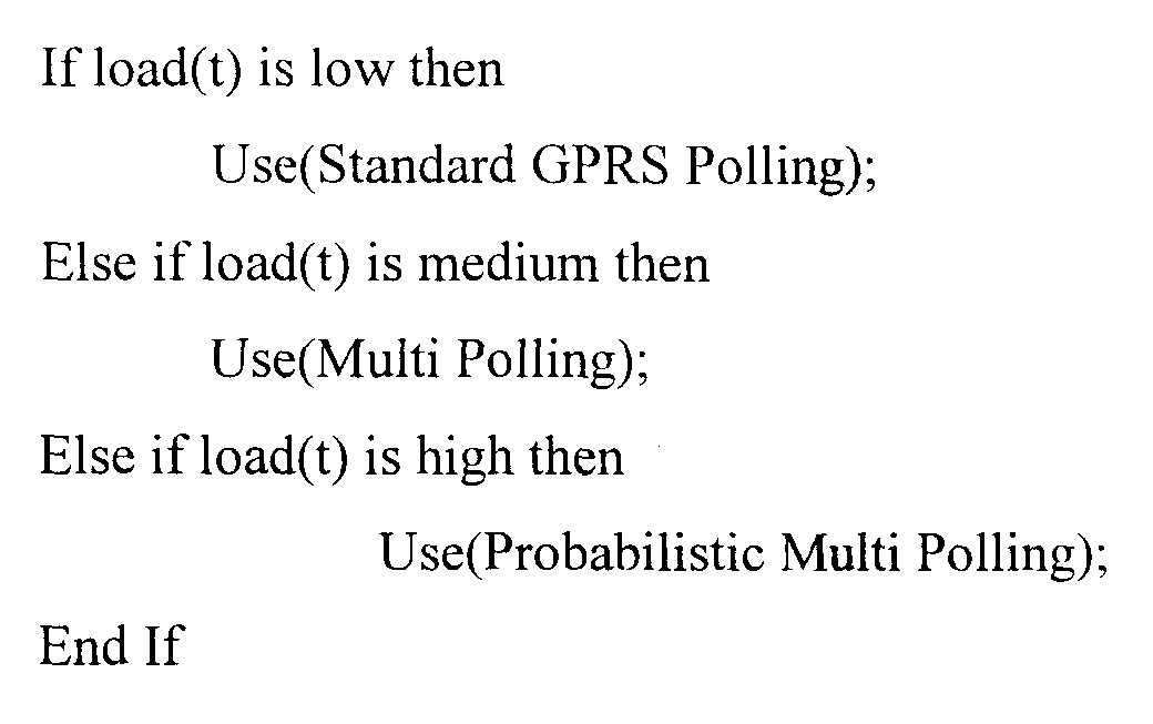
- multi polling permits more than one mobile to be polled in each time slot with a dedicated reply channels being signalled in the MAC header.
- Probabilistic multi polling is adopted when approaching the load limit of the cell.
- the elapsed time that a call has been in an active phase in order to select a channel for reply is taken from those channels that have been in their active phase the longest and therefore the most likely to become inactive the soonest.
- the mobiles reply time slots are grouped to allow the mobiles to contend for a reply channel selected in the same manner described above. In this manner it is thought that the polling will degrade fairly as load increases and spare channel become scarce.
- GPRS/EDGE General Packet Radio Service/Enhanced Data Rates for GPRS
- RR messages are signalled to the mobile by setting the payload Type field in the MAC header to control.
- RRBP Relative Reserve Block Period
- SP Supplementary Polling
- GPRS/EDGE mobiles When GPRS/EDGE mobiles request a voice service they are placed into a polling group, if in their silence phase, or given a channel, if in their active phase.
- the RR messages that such mobiles would be interested in under these circumstances are reassignments of their channels when active.
- the design of the Multi-polling header allows for this in the reply fields (see Reply Encoding section above). For this reason the RRBP and SP fields can be removed from the Multi-polling header when more than one mobile is polled in a given time slot.
- the CSN1 (Concrete Syntax Notation 1) coding for the multi-polling header is given below.
- the header length depends on the value of the first two bits in the header since their value selects the subsequent MAC structure.
- the definitions of the structures are also given below.
- the MAC header is the same as it would be for a standard GPRS MAC header in so far as it includes the SP, RRBP and Payload Type fields.
- the length of the polling code depends on the number of mobiles being polled. The explanation for this has been given in the Polling Code section above.
- the length of the reply field again depends on the number of mobile being polled. The explanation of the construction of the reply field is given in the Reply Encoding section.
Landscapes
- Engineering & Computer Science (AREA)
- Computer Networks & Wireless Communication (AREA)
- Signal Processing (AREA)
- Mobile Radio Communication Systems (AREA)
Abstract
Description
- <Single mobile structure>
- <POLLING CODE: bit(3)>
- <S/P : bit(1)>
- <RRPB : bit(2)>
- <PAYLOAD TYPE : bit(2)>
- <Spare Bits>;
- <Two Mobile struct>::=
- <POLLING CODE: bit(5)>
- <PAYLOAD TYPE : bit(2)>
- {<Reply Field: Reply Field struct>*2}
- <Spare Bits>;
<Reply Field struct>::=
- <USF_NEW: bit(3)>
- <REPLY_TS:bit(3)>
- <REPLY_FN: :bit(2)>;
Claims (18)
- A data transmission system comprising a base station having a radio transmitter and a receiver and a plurality of satellite stations each having a radio transmitter and a receiver, the transmitter of the base station and the receivers of the satellite stations all being tuned to the same downlink channel, and the transmitters of the satellite stations and the receiver of the base station all being tuned to a common uplink channel and at least one auxiliary uplink channel, the base station including control means for generating a succession of data packets and transmitting them to the satellite station, each data packet comprising a header section and a payload section, the header section being of variable configuration and length and containing a first uplink state flag identifying with a first selected satellite stations which when received by the first selected satellite station causes that satellite station alone to send a data packet back to the base station along the uplink channel, and at least one second uplink state flag identifying a second selected satellite station coupled with the identity of and time slot for, a said auxiliary uplink channel to cause the said second selected satellite station alone to send a data packet back to the base station along said auxiliary uplink channel in said time slot, whereby to effect multi-polling of said satellite station using a single packet of data.
- A data transmission system according to Claim 1, wherein control means is arranged to incorporate into the header of each said packet of data a code indicative of whether single polling, multi-polling or probabilistic multi-polling is required and wherein each said satellite station adapts itself to the requirement upon receipt of the code.
- A data transmission system according to Claim 2, wherein when the header includes a code indicative of single polling, the control means is arranged to incorporate into the header of each said packet of data, a polling code of three bits, and S/P code of one bit and RRPB code of two bits and a payload type code of two bits.
- A data transmission system according to Claim 2, wherein when the header of each packet of data includes a code indicative of multi-polling, the control means is arranged to incorporate into the header a polling code, a payload type code of two bits and a reply field : reply field structure code.
- A data transmission system according to Claim 4, wherein when a number x satellites are being polled the length of the polling code is ( x + 3) bits and the length of the reply field : reply structure code is x bits.
- A data transmission system according to Claim 5, wherein the control means is arranged to configure the header so that the reply field structure includes an USF of three bits, a reply time slot of two bits and a reply frequency of two bits.
- A data transmission system according to any preceding claim, wherein each said satellite comprises a mobile telephone and said uplink and downlink channels form part of a radio telephone network.
- A base station having a radio transmitter and a receiver for communication with a plurality of satellite stations, the transmitter being tuned to a predetermined downlink channel, and the receiver being tuned to a predetermined uplink channel and at least one auxiliary uplink channel, the base station including control means for generating a succession of data packets and transmitting them to the satellite stations, each data packet comprising a header section and a payload section, the header section being of variable configuration and length and containing a first uplink state flag identifying with a first selected satellite station and at least one second uplink state flag identifying a second selected satellite station coupled with the identity of and time slot for, a said auxiliary-uplink channel whereby to effect multi-polling of said satellite station using a single packet of data.
- A base station according to Claim 8, wherein control means is arranged to incorporate into the header of each said packet of data, a code indicative of whether single polling, multi-polling or probabilistic multi-polling is required.
- A base station according to Claim 9, wherein when the header includes a code indicative of single polling, the control means is arranged to incorporate into the header of each said packet of data, a polling code of three bits, and S/P code of one bit and RRPB code of two bits and a payload type code of two bits.
- A base station according to Claim 9, wherein when the header of each packet of data includes a code indicative of multi-polling, the control means is arranged to incorporate into the header a polling code, a payload type code of two bits and a reply field : reply field structure code.
- A base station according to Claim 11, wherein when a number x satellites are being polled the length of the polling code is ( x + 3) bits and the length of the reply field : reply structure code is x bits.
- A base station according to Claim 12, wherein the control means is arranged to configure the header so that the reply field structure includes an USF of three bits, a reply time slot of two bits and a reply frequency of two bits.
- A telephone network including a base station according to any one of Claims 8 to 13.
- A satellite station with a unique identity having a radio transmitter and a receiver, the receiver being tuned to a predetermined downlink channel, and the transmitter being tuned to a predetermined uplink channel and at least one auxiliary uplink channel, the satellite station including control means for receiving from a base station a succession of data packets, each data packet comprising a header section and a payload section, the header section being of variable configuration and length and containing a first uplink state flag carrying the identity of a first selected satellite station which if that identity corresponds with the said unique identity causes the control means to send a data packet back to the base station along the predetermined uplink channel, and at least one second uplink state flag carrying the identity of a second selected satellite station coupled with the identity of and time slot for, a said auxiliary uplink channel which if that identity corresponds with said unique identity causes the control means to send a data packet back to the base station along said auxiliary uplink channel in said time slot, whereby said satellite station is multi-polled using a single packet of data.
- A satellite station according to Claim 15, wherein the header of each said packet of data includes a code indicative of whether single polling, multi-polling or probabilistic multi-polling is required and wherein control means adapts itself to the requirement upon receipt of the code.
- A satellite station according to Claim 16, wherein when the header includes a code indicative of single polling, the control means is arranged to incorporate into the header of each said packet of data, a polling code of three bits, and S/P code of one bit and RRPB code of two bits and a payload type code of two bits.
- A mobile phone comprising a satellite station according to any one of Claims 14 to 16.
Priority Applications (1)
| Application Number | Priority Date | Filing Date | Title |
|---|---|---|---|
| EP00307835A EP1107619A3 (en) | 1999-12-10 | 2000-09-11 | Multi-polling system for GPRS |
Applications Claiming Priority (3)
| Application Number | Priority Date | Filing Date | Title |
|---|---|---|---|
| EP99309993 | 1999-12-10 | ||
| EP99309993 | 1999-12-10 | ||
| EP00307835A EP1107619A3 (en) | 1999-12-10 | 2000-09-11 | Multi-polling system for GPRS |
Publications (2)
| Publication Number | Publication Date |
|---|---|
| EP1107619A2 true EP1107619A2 (en) | 2001-06-13 |
| EP1107619A3 EP1107619A3 (en) | 2002-03-06 |
Family
ID=26073301
Family Applications (1)
| Application Number | Title | Priority Date | Filing Date |
|---|---|---|---|
| EP00307835A Withdrawn EP1107619A3 (en) | 1999-12-10 | 2000-09-11 | Multi-polling system for GPRS |
Country Status (1)
| Country | Link |
|---|---|
| EP (1) | EP1107619A3 (en) |
Family Cites Families (2)
| Publication number | Priority date | Publication date | Assignee | Title |
|---|---|---|---|---|
| FI104610B (en) * | 1997-03-27 | 2000-02-29 | Nokia Networks Oy | Allocation of a control channel in a packet radio network |
| FR2771885B1 (en) * | 1997-11-28 | 2000-03-24 | Alsthom Cge Alcatel | METHOD FOR ALLOCATING TRANSMISSION CHANNELS TO A MOBILE STATION, IN PACKET MODE |
-
2000
- 2000-09-11 EP EP00307835A patent/EP1107619A3/en not_active Withdrawn
Also Published As
| Publication number | Publication date |
|---|---|
| EP1107619A3 (en) | 2002-03-06 |
Similar Documents
| Publication | Publication Date | Title |
|---|---|---|
| US6075779A (en) | Random access channel congestion control for broadcast teleservice acknowledgment messages | |
| US6226279B1 (en) | Allowing several multiple access schemes for packet data in a digital cellular communication system | |
| RU2216100C2 (en) | Method for planning readings of variable blocks with aid of status flag of ascending communication line in burst data transmission system | |
| US6611536B1 (en) | System and method for integrating voice and data on a single RF channel | |
| AU748660B2 (en) | Improvements in and relating to data transmission | |
| JP2001504658A (en) | Time division transmission system for short message acknowledgment and method thereof | |
| KR101391486B1 (en) | Allocating traffic channels in a communications system | |
| EP1107620B1 (en) | Multi-polling system for GPRS | |
| US20040042508A1 (en) | Method for rapidly allocating radio resources to logical channels in a down-link direction | |
| EP1107619A2 (en) | Multi-polling system for GPRS | |
| US7088686B1 (en) | Radio method and device having a frame structure | |
| WO1999011084A1 (en) | Apparatus and method for transmitting data | |
| KR100393722B1 (en) | Improvements in and relating to data transmission systems | |
| EP0629094A2 (en) | Improvements in or relating to cellular mobile radio systems | |
| EP0860061B1 (en) | Digital telephony using control messages transmitted in time slots for rf frequency allocation | |
| US7301932B1 (en) | Method and system for multiple access in a radiocommunication system | |
| GB2313019A (en) | Direct mode communications repeater |
Legal Events
| Date | Code | Title | Description |
|---|---|---|---|
| PUAI | Public reference made under article 153(3) epc to a published international application that has entered the european phase |
Free format text: ORIGINAL CODE: 0009012 |
|
| AK | Designated contracting states |
Kind code of ref document: A2 Designated state(s): AT BE CH CY DE DK ES FI FR GB GR IE IT LI LU MC NL PT SE |
|
| AX | Request for extension of the european patent |
Free format text: AL;LT;LV;MK;RO;SI |
|
| PUAL | Search report despatched |
Free format text: ORIGINAL CODE: 0009013 |
|
| AK | Designated contracting states |
Kind code of ref document: A3 Designated state(s): AT BE CH CY DE DK ES FI FR GB GR IE IT LI LU MC NL PT SE |
|
| AX | Request for extension of the european patent |
Free format text: AL;LT;LV;MK;RO;SI |
|
| AKX | Designation fees paid | ||
| REG | Reference to a national code |
Ref country code: DE Ref legal event code: 8566 |
|
| STAA | Information on the status of an ep patent application or granted ep patent |
Free format text: STATUS: THE APPLICATION IS DEEMED TO BE WITHDRAWN |
|
| 18D | Application deemed to be withdrawn |
Effective date: 20020907 |