EP1107656A2 - Elektrische Einrichtung - Google Patents
Elektrische Einrichtung Download PDFInfo
- Publication number
- EP1107656A2 EP1107656A2 EP00126268A EP00126268A EP1107656A2 EP 1107656 A2 EP1107656 A2 EP 1107656A2 EP 00126268 A EP00126268 A EP 00126268A EP 00126268 A EP00126268 A EP 00126268A EP 1107656 A2 EP1107656 A2 EP 1107656A2
- Authority
- EP
- European Patent Office
- Prior art keywords
- profile
- housing
- proof
- gap
- profile bracket
- Prior art date
- Legal status (The legal status is an assumption and is not a legal conclusion. Google has not performed a legal analysis and makes no representation as to the accuracy of the status listed.)
- Granted
Links
- 239000000463 material Substances 0.000 claims description 3
- 239000002360 explosive Substances 0.000 claims 1
- 230000015556 catabolic process Effects 0.000 description 2
- 239000002131 composite material Substances 0.000 description 2
- 238000004880 explosion Methods 0.000 description 2
- 238000011161 development Methods 0.000 description 1
- 230000018109 developmental process Effects 0.000 description 1
- 210000001061 forehead Anatomy 0.000 description 1
- 239000000203 mixture Substances 0.000 description 1
- 239000007787 solid Substances 0.000 description 1
Images


Classifications
-
- H—ELECTRICITY
- H05—ELECTRIC TECHNIQUES NOT OTHERWISE PROVIDED FOR
- H05K—PRINTED CIRCUITS; CASINGS OR CONSTRUCTIONAL DETAILS OF ELECTRIC APPARATUS; MANUFACTURE OF ASSEMBLAGES OF ELECTRICAL COMPONENTS
- H05K5/00—Casings, cabinets or drawers for electric apparatus
- H05K5/06—Hermetically-sealed casings
- H05K5/063—Hermetically-sealed casings sealed by a labyrinth structure provided at the joining parts
-
- H—ELECTRICITY
- H02—GENERATION; CONVERSION OR DISTRIBUTION OF ELECTRIC POWER
- H02B—BOARDS, SUBSTATIONS OR SWITCHING ARRANGEMENTS FOR THE SUPPLY OR DISTRIBUTION OF ELECTRIC POWER
- H02B1/00—Frameworks, boards, panels, desks, casings; Details of substations or switching arrangements
- H02B1/26—Casings; Parts thereof or accessories therefor
- H02B1/28—Casings; Parts thereof or accessories therefor dustproof, splashproof, drip-proof, waterproof or flameproof
Definitions
- the invention relates to an electrical device a housing of type of protection flameproof enclosure "d".
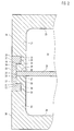
- housing 1 corresponds to the type of protection flameproof enclosure "d" and has a trough-shaped housing part 2, a flat cover Housing part 3 and a profile bracket 4th on. That forming the edge area of the housing part 3 Wall part 5 is located on the end face of a wall part 6 of the Housing part 2.
- the profile bracket 4 connects the two housing parts 2, 3 with each other, in such a way that the housing parts 2, 3 even in the case of an ignitable Mixture inside explosion occurring be held together firmly and between the wall parts 5, 6 an ignition-proof gap 7 is formed.
- the cross section of the profile bracket 4 is essentially roughly C-shaped.
- the profile clip 4 a base web 8 and two side webs 9, 10 on the spaced apart and on one and the same side of the base web 8 are arranged at right angles to this.
- the base web 8 and the side webs 9, 10 themselves can expediently have a rectangular cross section.
- the wall part 6 of the Housing part 2 have a recess into which a Part of the base web 8 and the side web 9 form-fitting intervention.
- This intervention can advantageously be designed in this way be that an inner surface 11 of the base web 8 parallel to a contact surface 12 of the housing part 2 and one End face 18 of the housing part 3 lies, with a distance between the inner surface 11 and the contact surface 12 or the end face 18 can occur, which is preferably is less than 1 mm.
- the base bridge 8 is located the profile bracket 4 so deep in the recess that an outer surface 13 of the base web 8 with an outer side 14 of the wall part 6 forms a common plane.
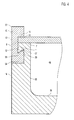
- pressure-resistant housing 20th is located between the wall parts 21, 22 of the tub or.
- hood-shaped housing parts 23, 24 an additional wall 25, which divides the housing 20.
- the distance between the mutually facing end faces of the wall parts 21, 22 is only slightly larger than the thickness of the additional wall 25, so that the additional wall 25 largely free of play in the clearance area is held.
- the housing parts 23, 24 are positively connected by the profile bracket 29, that even in the case of a occurring inside the housing Explosion solid cohesion is guaranteed.
- the Profile bracket 29 is like the profile clip 4 of the previous described embodiment essentially C-shaped and has one in cross section rectangular base 30 and two also rectangular Side webs 31, 32 on one and same side of the base web 30 at a distance from each other are arranged.
- Both the wall part 21 and the wall part 22 have each have a recess in which the profile bracket 29 is stored.
- the inner surface 33 of the base web can 30 without or with a distance that is preferred is less than 1 mm, parallel to the contact surfaces 34 of the housing parts 23, 24 and an end face 35 of the Additional wall 25 lie.
- the profile bracket 29 is in the Recesses in the wall parts 21, 22 mounted such that the outer sides 36 of the wall parts 21, 22 and the outer surface 37 of the base bridge 30 form a common level.
- the Side webs 31, 32 and the support surfaces 39 of the housing parts 23, 24 each have an ignition-proof additional gap 40 be formed. These additional breakdown-proof gaps 40 extend parallel to the ignition-proof Columns 28 and are shorter than the latter trained, but can also be longer.
- FIG. 3 housing 44 is similar to that in FIG. 1 illustrated embodiment. Indeed is the edge area of the upper housing part 45 stepped and the profile bracket 46 has on the base bar 8 the short side bar 9 and one long side bridge 47.
- This side web 47 engages the wall part 48 of the housing part 45, which on the wall part 6 of the lower housing part 2 rests.
- the housing 52 of FIG. 4 is also similar to that in the FIG. 1 illustrated embodiment. Indeed the profile bracket 53 has a dovetail shape Side web 54 on, in a correspondingly dovetail shape designed recess of the wall part 55 of the lower housing part 56 is mounted. So get lost the stop surface 57 of the side web 54 and the support surface 58 of the wall part 55 and also the flame-proof Additional gap 59 obliquely or inclined to the ignition-proof Gap 7 between the upper housing part 3 and the lower housing part 56.
- the profile bracket 4, 29, 46, 53 can be holistic consist of the same material, that is, both the base web 8, 30 and the respective associated Side bars 9, 10, 31, 32, 47, 54 made of the same material are made in one piece.
- the profile bracket 4, 29, 46, 53 against unintentional loosening secure it can be useful at least one of the Housing parts 2, 3, 23, 24, 45.56 e.g. not here illustrated threaded screws can be set.
- the investment level is plan, so that a flat anti-ignition device Profile gap 60 is formed.
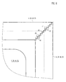
- the in the FIG. 6 housing corner area shown also run at right angles and bump it too here two ends of the profile clips 4, 29, 46, 53 vertically on each other, but with their respective Longitudinal profile bracket sloping ends.
- the colliding ends each have a profile consisting of protrusions 41 and recesses 42 is formed, which preferably as triangular teeth with triangular tooth gaps in between are trained.
- the projections 41 and recesses 42 also differently design and for example as a rectangular, trapezoidal or sawtooth-like teeth and tooth gaps to execute.
- the projections 41 of a profile bracket 4, 29, 46, 53 engage in the recesses 42 of the others Profile bracket 4, 29, 46, 53 so that in one 45 ° miter a tooth composite with a flame-proof Profile gap 43 is formed.
- the in the FIG. 7 corner area shown is polygonal designed and owns two tooth composites interlocking protrusions 41 and recesses 42 as well as two flame-proof profile gaps 43.
- the Projections 41 and recesses 42 also here as triangular Teeth with triangular in between Tooth gaps formed.
Landscapes
- Engineering & Computer Science (AREA)
- Power Engineering (AREA)
- Microelectronics & Electronic Packaging (AREA)
- Ignition Installations For Internal Combustion Engines (AREA)
- Connection Of Plates (AREA)
- Surgical Instruments (AREA)
- Beans For Foods Or Fodder (AREA)
- Control And Other Processes For Unpacking Of Materials (AREA)
- Cookers (AREA)
- Battery Mounting, Suspending (AREA)
Abstract
Description
- FIG. 1
- einen Teil eines erfindungsgemäßen Gehäuses mit einem planen oberen Gehäuseteil und einer Profilklammer mit gleichen Seitenstegen in einer geschnittenen Darstellung,
- FIG. 2
- einen Teil eines erfindungsgemäßen Gehäuses mit einem haubenförmigen oberen Gehäuseteil und einer Profilklammer gemäß FIG. 1 in einer geschnittenen Darstellung,
- FIG. 3
- einen Teil eines erfindungsgemäßen Gehäuses ähnlich der FIG. 1, jedoch mit einem stufenförmigen oberen Gehäuseteil und einer Profilklammer mit ungleich langen Seitenstegen in einer geschnittenen Darstellung,
- FIG. 4
- einen Teil eines erfindungsgemäßen Gehäuses ähnlich der FIG. 1, jedoch mit einer zum Teil schwalbenschwanzförmig gestalteten Profilklammer in einer geschnittenen Darstellung,
- FIG. 5
- einen rechtwinklig ausgeführten Eckbereich eines erfindungsgemäßen Gehäuses mit stumpf aufeinanderstoßenden Profilklammerenden,
- FIG. 6
- einen rechtwinklig ausgeführten Eckbereich eines erfindungsgemäßen Gehäuses mit in einem 45° Winkel aneinanderstoßenden Profilklammerenden und
- FIG. 7
- einen polygonartig ausgeführten Eckbereich eines erfindungsgemäßen Gehäuses mit schräg aneinanderstoßenden Profilklammerenden.
Claims (23)
- Elektrische Einrichtung mit einem Gehäuse (1, 20, 44, 52) der Zündschutzart druckfeste Kapselung "d", mindestens zwei Gehäuseteilen (2, 3, 23, 24, 45, 56) mit einander zugewandten Wandteilen (5, 6, 21, 22, 48, 55), einem zwischen den Wandteilen (5, 6, 21, 22, 48, 55) vorgesehenen zünddurchschlagsicheren Spalt (7, 28) und einer die Gehäuseteile (2, 3, 23, 24, 45, 56) gegen die Kraft eines explosionsartigen Gehäuseinnendrucks formschlüssig verbindenden Profilklammer (4, 29, 46, 53).
- Einrichtung nach vorstehendem Anspruch, dadurch gekennzeichnet, dass die Profilklammer (4, 29, 46, 53) im Querschnitt etwa C-förmig ist.
- Einrichtung nach einem der vorstehenden Ansprüche, dadurch gekennzeichnet, dass die Profilklammer (4, 29, 46, 53) einen Grundsteg (8, 30) und zwei Seitenstege (9, 10, 31, 32, 47, 54) aufweist, wobei der eine Seitensteg (9, 32, 54) mit dem einen Gehäuseteil (2, 24, 56) und der andere Seitensteg (10, 31, 47) mit dem anderen Gehäuseteil (3, 23, 45) korrespondiert.
- Einrichtung nach einem der vorstehenden Ansprüche, dadurch gekennzeichnet, dass die zueinander beabstandeten Seitenstege (9, 10, 31, 32, 47, 54) der Profilklammer (4, 29, 46, 53) an ein und derselben Seite des im Querschnitt bevorzugt rechteckförmigen Grundstegs (8, 30) winkelbildend, vorzugsweise im wesentlichen rechtwinklig zu letzterem angeordnet sind.
- Einrichtung nach einem der vorstehenden Ansprüche, dadurch gekennzeichnet, dass zwischen einer Anschlagfläche (15, 38, 49, 57) des Seitenstegs (9, 10, 31, 32, 47, 54) der Profilklammer (4, 29, 46, 53) und einer Stützfläche (16, 39, 50, 58) des Gehäuseteils (2, 3, 23, 24, 45, 56) ein zünddurchschlagsicherer Zusatzspalt (17, 40, 51, 59) gebildet ist.
- Einrichtung nach einem der vorstehenden Ansprüche, dadurch gekennzeichnet, dass die Anschlagfläche (15, 38) des Seitenstegs (9, 10, 31, 32) der Profilklammer (4, 29) und die Stützfläche (16, 39) des Gehäuseteils (2, 3, 23, 24) sowie der zünddurchschlagsichere Zusatzspalt (17, 40) parallel zu dem zünddurchschlagsicheren Spalt (7, 28) angeordnet sind.
- Einrichtung nach einem der vorstehenden Ansprüche, dadurch gekennzeichnet, dass die Anschlagfläche (57) des Seitenstegs (54) der Profilklammer (53) und die Stützfläche (58) des Gehäuseteils (56) sowie der zünddurchschlagsichere Zusatzspalt (59) schräg zu dem zünddurchschlagsicheren Spalt (7, 28) angeordnet sind.
- Einrichtung nach einem der vorstehenden Ansprüche, dadurch gekennzeichnet, dass der zünddurchschlagsichere Zusatzspalt (17, 40, 59) zwischen der Anschlagfläche (15, 38, 57) des Seitenstegs (9, 10, 31, 32, 54) und der Stützfläche (16, 39, 58) des Gehäuseteils (2, 3, 23, 24, 56) kürzer ist als der zünddurchschlagsichere Spalt (7, 28) zwischen den beiden Gehäuseteilen (2, 3, 23, 24, 45).
- Einrichtung nach einem der vorstehenden Ansprüche, dadurch gekennzeichnet, dass die Länge des zünddurchschlagsicheren Zusatzspaltes (51) zwischen der Anschlagfläche (49) des Seitenstegs (47) und der Stützfläche (50) des Gehäuseteils (45) gleich oder größer ist als der zünddurchschlagsichere Spalt (7) zwischen den beiden Gehäuseteilen (2, 45).
- Einrichtung nach einem der vorstehenden Ansprüche, dadurch gekennzeichnet, dass mindestens ein Teil der Profilklammer (4, 29, 46, 53) in einer Ausnehmung des Gehäuseteils (2, 23, 24) gelagert ist.
- Einrichtung nach einem der vorstehenden Ansprüche, dadurch gekennzeichnet, dass eine Außenfläche (13, 37) des Grundstegs (8, 30) der Profilklammer (4, 29, 46, 53) mit einer Außenseite (14, 36) mindestens eines der Gehäuseteile (2, 23, 24, 56) im wesentlichen eine gemeinsame Ebene bildet.
- Einrichtung nach einem der vorstehenden Ansprüche, dadurch gekennzeichnet, dass eine dem Gehäuse (1, 20, 44, 52) zugewandte Innenfläche (11, 33) des Grundstegs (8, 30) der Profilklammer (4, 29, 46, 53) parallel zu einer Anlagefläche (12, 34) des Gehäuseteils (2, 3, 23, 24, 56) angeordnet ist.
- Einrichtung nach einem der vorstehenden Ansprüche, dadurch gekennzeichnet, dass zwischen der Innenfläche (11, 33,) des Grundstegs (8, 30) der Profilklammer (4, 29, 46, 53) und der Anlagefläche (12, 34) des Gehäuseteils (2, 23, 24, 56) ein Abstand gebildet ist, der bevorzugt kleiner als 1 mm ist.
- Einrichtung nach einem der vorstehenden Ansprüche, dadurch gekennzeichnet, dass zwischen den beiden Wandteilen (23, 24) des Gehäuses (20) eine Zusatzwand (25) angeordnet ist.
- Einrichtung nach einem der vorstehenden Ansprüche, dadurch gekennzeichnet, dass der zünddurchshlagsichere Spalt (28) zwischen dem Wandteil (21, 22) des Gehäuses (20) und einer Seitenfläche (26, 27) der Zusatzwand (25) gebildet ist.
- Einrichtung nach einem der vorstehenden Ansprüche, dadurch gekennzeichnet, dass eine Stirnfläche (35) der Zusatzwand (25) an die Innenfläche (33) der Profilklammer (29) angrenzt.
- Einrichtung nach einem der vorstehenden Ansprüche, dadurch gekennzeichnet, dass an einem Gehäuseeckbereich die Enden zweier Profilklammern (4, 29, 46, 53) aneinanderstoßen, derart, dass ein ebener oder unebener zünddurchschlagsicherer Profilspalt (43, 60) gebildet ist.
- Einrichtung nach einem der vorstehenden Ansprüche, dadurch gekennzeichnet, dass an mindestens einem Ende der einen Profilklammer (4, 29, 46, 53) und an mindestens einem Ende der anderen Profilklammer (4, 29, 46, 53) je ein aus Vorsprüngen (41) und Rücksprüngen (42) gebildetes Profil gebildet ist, wobei die Vorsprünge (41) der einen Profilklammer (4, 29, 46, 53) in die Rücksprünge (42) der anderen Profilklammer (4, 29, 46, 53) eingreifen und dazwischen der zünddurchschlagsichere Profilspalt (43) besteht.
- Einrichtung nach einem der vorstehenden Ansprüche, dadurch gekennzeichnet, dass die Vorsprünge (41) und Rücksprünge (42) der Profilklammer (4, 29, 46, 53) als Zähne bzw. Zahnlücken ausgebildet und vorzugsweise dreieckförmig sind.
- Einrichtung nach einem der vorstehenden Ansprüche, dadurch gekennzeichnet, dass der zünddurchschlagsichere Profilspalt (43) in einem Profilklammer-Eckbereich als 45°-Gehrung ausgebildet ist.
- Einrichtung nach einem der vorstehenden Ansprüche, dadurch gekennzeichnet, dass der Profilklammer-Eckbereich polygonförmig ist und mindestens zwei zünddurchschlagsichere Profilspalte (43) aufweist.
- Einrichtung nach einem der vorstehenden Ansprüche, dadurch gekennzeichnet, dass die Profilklammer (4, 29, 46, 53) mit dem Grundsteg (8, 30) und den Seitenstegen (9, 10, 31, 32, 47, 54) materialeinheitlich einstückig ausgeführt ist.
- Einrichtung nach einem der vorstehenden Ansprüche, dadurch gekennzeichnet, dass die Profilklammer (4, 29, 46, 53) an mindestens einem der Gehäuseteile (2, 3, 23, 24, 45, 56) unverlierbar festgelegt ist.
Applications Claiming Priority (2)
| Application Number | Priority Date | Filing Date | Title |
|---|---|---|---|
| DE19959384A DE19959384B4 (de) | 1999-12-09 | 1999-12-09 | Elektrische Einrichtung |
| DE19959384 | 1999-12-09 |
Publications (3)
| Publication Number | Publication Date |
|---|---|
| EP1107656A2 true EP1107656A2 (de) | 2001-06-13 |
| EP1107656A3 EP1107656A3 (de) | 2002-05-15 |
| EP1107656B1 EP1107656B1 (de) | 2007-10-03 |
Family
ID=7932007
Family Applications (1)
| Application Number | Title | Priority Date | Filing Date |
|---|---|---|---|
| EP00126268A Expired - Lifetime EP1107656B1 (de) | 1999-12-09 | 2000-12-01 | Elektrische Einrichtung |
Country Status (5)
| Country | Link |
|---|---|
| US (1) | US6753473B2 (de) |
| EP (1) | EP1107656B1 (de) |
| AT (1) | ATE375076T1 (de) |
| CA (1) | CA2328281A1 (de) |
| DE (2) | DE19959384B4 (de) |
Cited By (4)
| Publication number | Priority date | Publication date | Assignee | Title |
|---|---|---|---|---|
| EP3579671A1 (de) * | 2018-06-05 | 2019-12-11 | R. STAHL Schaltgeräte GmbH | Gehäuse der schutzart druckfeste kapselung |
| DE102019102832A1 (de) | 2019-02-05 | 2020-08-06 | R. Stahl Schaltgeräte GmbH | Explosionsgeschütztes Gehäuse und Verfahren zu dessen Montage |
| DE102020133606B3 (de) | 2020-12-15 | 2021-12-30 | R. Stahl Schaltgeräte GmbH | Explosionsgeschütztes Gehäuse mit herausnehmbarer Mittelstrebe |
| RU2803939C2 (ru) * | 2019-02-05 | 2023-09-22 | Р. Шталь Шальтгерете Гмбх | Взрывозащищенный корпус и способ его монтажа |
Families Citing this family (10)
| Publication number | Priority date | Publication date | Assignee | Title |
|---|---|---|---|---|
| DE112010006129B4 (de) | 2010-01-05 | 2024-06-13 | Eaton Intelligent Power Limited | Gehäuseklemme und Klemmensysteme |
| US8602245B2 (en) * | 2010-01-05 | 2013-12-10 | Cooper Technologies Company | Enclosure clamps and clamp systems |
| MX2012007820A (es) | 2010-01-05 | 2012-07-25 | Cooper Technologies Co | Abrazadera y sistemas de abrazaderas para contenedor. |
| DE202012100272U1 (de) * | 2012-01-26 | 2012-02-24 | Keba Ag | Gehäuse zur Aufnahme elektrotechnischer Komponenten |
| CN105071103A (zh) * | 2015-08-05 | 2015-11-18 | 徐州科亚机电有限公司 | 一种电动车控制器及其组装工艺 |
| TWI650057B (zh) * | 2016-12-09 | 2019-02-01 | 群暉科技股份有限公司 | 電子裝置 |
| DE102018118195B4 (de) | 2018-07-27 | 2020-06-04 | R. Stahl Schaltgeräte GmbH | Explosionssicheres Gehäuse mit geteiltem Deckel |
| US11096301B2 (en) * | 2019-01-03 | 2021-08-17 | Magna Electronics Inc. | Vehicular radar sensor with mechanical coupling of sensor housing |
| DE102019131195A1 (de) | 2019-11-19 | 2021-05-20 | R. Stahl Schaltgeräte GmbH | Gehäuse |
| US12258793B2 (en) * | 2022-09-13 | 2025-03-25 | Brose Schließsysteme GmbH & Co. Kommanditgesellschaft | Motor vehicle latch seal |
Family Cites Families (8)
| Publication number | Priority date | Publication date | Assignee | Title |
|---|---|---|---|---|
| FR1174709A (fr) * | 1957-01-15 | 1959-03-16 | Fermeture rapide pour coffret anti-déflagrant | |
| FR1344898A (fr) * | 1961-11-28 | 1963-12-06 | Zaklady Wytworcze Aparatury Ro | Installation de coupure à haute tension protégée contre les coups de grisou et les explosions |
| US3974933A (en) * | 1975-11-14 | 1976-08-17 | General Signal Corporation | Explosion proof and watertight enclosure with inspectable means for verifying validity of reclosure |
| DE2849490C2 (de) * | 1978-11-15 | 1984-04-26 | O & K Orenstein & Koppel Ag, 1000 Berlin | Mittels Laufringen gelagerte Drehtrommel |
| ES239718Y (es) * | 1978-11-27 | 1979-05-16 | Recipiente estanco para aparatos electricos | |
| JPH05185777A (ja) * | 1992-01-08 | 1993-07-27 | Ryoden Kasei Co Ltd | Icカード |
| US5959839A (en) * | 1997-01-02 | 1999-09-28 | At&T Corp | Apparatus for heat removal using a flexible backplane |
| JP3597368B2 (ja) * | 1998-02-16 | 2004-12-08 | アルプス電気株式会社 | 電子機器 |
-
1999
- 1999-12-09 DE DE19959384A patent/DE19959384B4/de not_active Expired - Fee Related
-
2000
- 2000-12-01 EP EP00126268A patent/EP1107656B1/de not_active Expired - Lifetime
- 2000-12-01 DE DE50014692T patent/DE50014692D1/de not_active Expired - Lifetime
- 2000-12-01 AT AT00126268T patent/ATE375076T1/de not_active IP Right Cessation
- 2000-12-11 US US09/733,347 patent/US6753473B2/en not_active Expired - Fee Related
- 2000-12-11 CA CA002328281A patent/CA2328281A1/en not_active Abandoned
Cited By (12)
| Publication number | Priority date | Publication date | Assignee | Title |
|---|---|---|---|---|
| EP3579671A1 (de) * | 2018-06-05 | 2019-12-11 | R. STAHL Schaltgeräte GmbH | Gehäuse der schutzart druckfeste kapselung |
| WO2019233986A1 (de) * | 2018-06-05 | 2019-12-12 | R. Stahl Schaltgeräte GmbH | Gehäuse der schutzart druckfeste kapselung |
| CN112438076A (zh) * | 2018-06-05 | 2021-03-02 | R.施塔尔开关设备有限责任公司 | 防护类型为耐压封装的壳体 |
| US11690181B2 (en) | 2018-06-05 | 2023-06-27 | R. Stahl Schaltgeräte GmbH | Flameproof housing |
| DE102019102832A1 (de) | 2019-02-05 | 2020-08-06 | R. Stahl Schaltgeräte GmbH | Explosionsgeschütztes Gehäuse und Verfahren zu dessen Montage |
| WO2020160937A1 (de) | 2019-02-05 | 2020-08-13 | R. Stahl Schaltgeräte GmbH | Explosionsgeschütztes gehäuse und verfahren zu dessen montage |
| DE102019102832B4 (de) | 2019-02-05 | 2021-09-09 | R. Stahl Schaltgeräte GmbH | Explosionsgeschütztes Gehäuse und Verfahren zu dessen Montage |
| RU2803939C2 (ru) * | 2019-02-05 | 2023-09-22 | Р. Шталь Шальтгерете Гмбх | Взрывозащищенный корпус и способ его монтажа |
| US12171069B2 (en) | 2019-02-05 | 2024-12-17 | R. Stahl Schaltgeräte GmbH | Explosion-proof housing and method for the assembly thereof |
| DE102020133606B3 (de) | 2020-12-15 | 2021-12-30 | R. Stahl Schaltgeräte GmbH | Explosionsgeschütztes Gehäuse mit herausnehmbarer Mittelstrebe |
| WO2022128231A1 (de) | 2020-12-15 | 2022-06-23 | R. Stahl Schaltgeräte GmbH | Explosionsgeschütztes gehäuse mit herausnehmbarer mittelstrebe |
| US12418162B2 (en) | 2020-12-15 | 2025-09-16 | R. Stahl Schaltgeräte GmbH | Explosion-proof housing comprising removable central strut |
Also Published As
| Publication number | Publication date |
|---|---|
| US20010006111A1 (en) | 2001-07-05 |
| DE19959384B4 (de) | 2007-01-18 |
| DE19959384A1 (de) | 2001-10-31 |
| EP1107656A3 (de) | 2002-05-15 |
| ATE375076T1 (de) | 2007-10-15 |
| CA2328281A1 (en) | 2001-06-09 |
| DE50014692D1 (de) | 2007-11-15 |
| EP1107656B1 (de) | 2007-10-03 |
| US6753473B2 (en) | 2004-06-22 |
Similar Documents
| Publication | Publication Date | Title |
|---|---|---|
| EP1107656A2 (de) | Elektrische Einrichtung | |
| DE202020107451U1 (de) | Trennvorrichtung | |
| DE29500711U1 (de) | Schutzwand für Unterstände, Lagerplätze o.dgl. und zu ihrer Herstellung bestimmter Bausatz | |
| DE8010258U1 (de) | Bauelement, insbesondere aus beton | |
| DE29921637U1 (de) | Elektrische Einrichtung | |
| DE2650180C3 (de) | Steigeisen | |
| AT12713U1 (de) | Baustein | |
| WO1984001598A1 (fr) | Installation de separation pour huisserie de porte sur planchers de hauteurs differentes | |
| DE102008016835B4 (de) | Glasfalzeinlage aus Kunststoff | |
| EP0000575A2 (de) | Zaun aus an Pfosten befestigbaren, grossflächigen Zaunelementen | |
| WO2015144297A1 (de) | Lärmschutzwand | |
| DE1459740A1 (de) | Verbundpflasterstein | |
| DE202012102383U1 (de) | Auflagebock | |
| DE4405977C2 (de) | Konsole für die Abstützung einer Gerüstbühne | |
| DE8808533U1 (de) | Zaungitter mit Sicherungsvorrichtung | |
| DE202010003097U1 (de) | Einsteckschloss und Stulpkörper zur Verwendung bei derartigen Einsteckschlössern | |
| DE60103966T2 (de) | Rahmenprofil | |
| EP3686368B1 (de) | Geländerbrüstung | |
| DE202024105710U1 (de) | Geländer, insbesondere Geländer aus Holz | |
| DE8511173U1 (de) | Wandverkleidung | |
| EP1767715A2 (de) | Glasbausteinwand | |
| DE102010015574A1 (de) | Trennwandsystem | |
| DE202013100503U1 (de) | Abschlussprofil für Wanddämmungen | |
| DE29908958U1 (de) | Sicherheitsverbindung von Rundstreben | |
| DE9016109U1 (de) | Stützfuß für Pfosten |
Legal Events
| Date | Code | Title | Description |
|---|---|---|---|
| PUAI | Public reference made under article 153(3) epc to a published international application that has entered the european phase |
Free format text: ORIGINAL CODE: 0009012 |
|
| 17P | Request for examination filed |
Effective date: 20001201 |
|
| AK | Designated contracting states |
Kind code of ref document: A2 Designated state(s): AT BE CH CY DE DK ES FI FR GB GR IE IT LI LU MC NL PT SE TR |
|
| AX | Request for extension of the european patent |
Free format text: AL;LT;LV;MK;RO;SI |
|
| PUAL | Search report despatched |
Free format text: ORIGINAL CODE: 0009013 |
|
| AK | Designated contracting states |
Kind code of ref document: A3 Designated state(s): AT BE CH CY DE DK ES FI FR GB GR IE IT LI LU MC NL PT SE TR |
|
| AX | Request for extension of the european patent |
Free format text: AL;LT;LV;MK;RO;SI |
|
| AKX | Designation fees paid |
Designated state(s): AT BE CH CY DE DK ES FI FR GB GR IE IT LI LU MC NL PT SE TR |
|
| 17Q | First examination report despatched |
Effective date: 20060804 |
|
| GRAP | Despatch of communication of intention to grant a patent |
Free format text: ORIGINAL CODE: EPIDOSNIGR1 |
|
| GRAS | Grant fee paid |
Free format text: ORIGINAL CODE: EPIDOSNIGR3 |
|
| GRAA | (expected) grant |
Free format text: ORIGINAL CODE: 0009210 |
|
| AK | Designated contracting states |
Kind code of ref document: B1 Designated state(s): AT BE CH CY DE DK ES FI FR GB GR IE IT LI LU MC NL PT SE TR |
|
| REG | Reference to a national code |
Ref country code: GB Ref legal event code: FG4D Free format text: NOT ENGLISH |
|
| GBT | Gb: translation of ep patent filed (gb section 77(6)(a)/1977) |
Effective date: 20071003 |
|
| REG | Reference to a national code |
Ref country code: CH Ref legal event code: EP |
|
| REG | Reference to a national code |
Ref country code: IE Ref legal event code: FG4D Free format text: LANGUAGE OF EP DOCUMENT: GERMAN |
|
| REF | Corresponds to: |
Ref document number: 50014692 Country of ref document: DE Date of ref document: 20071115 Kind code of ref document: P |
|
| NLV1 | Nl: lapsed or annulled due to failure to fulfill the requirements of art. 29p and 29m of the patents act | ||
| PG25 | Lapsed in a contracting state [announced via postgrant information from national office to epo] |
Ref country code: NL Free format text: LAPSE BECAUSE OF FAILURE TO SUBMIT A TRANSLATION OF THE DESCRIPTION OR TO PAY THE FEE WITHIN THE PRESCRIBED TIME-LIMIT Effective date: 20071003 Ref country code: SE Free format text: LAPSE BECAUSE OF FAILURE TO SUBMIT A TRANSLATION OF THE DESCRIPTION OR TO PAY THE FEE WITHIN THE PRESCRIBED TIME-LIMIT Effective date: 20080103 Ref country code: ES Free format text: LAPSE BECAUSE OF FAILURE TO SUBMIT A TRANSLATION OF THE DESCRIPTION OR TO PAY THE FEE WITHIN THE PRESCRIBED TIME-LIMIT Effective date: 20080114 |
|
| PG25 | Lapsed in a contracting state [announced via postgrant information from national office to epo] |
Ref country code: PT Free format text: LAPSE BECAUSE OF FAILURE TO SUBMIT A TRANSLATION OF THE DESCRIPTION OR TO PAY THE FEE WITHIN THE PRESCRIBED TIME-LIMIT Effective date: 20080303 |
|
| REG | Reference to a national code |
Ref country code: IE Ref legal event code: FD4D |
|
| ET | Fr: translation filed | ||
| BERE | Be: lapsed |
Owner name: BARTEC COMPONENTEN UND SYSTEME G.M.B.H. Effective date: 20071231 |
|
| PG25 | Lapsed in a contracting state [announced via postgrant information from national office to epo] |
Ref country code: MC Free format text: LAPSE BECAUSE OF NON-PAYMENT OF DUE FEES Effective date: 20071231 Ref country code: DK Free format text: LAPSE BECAUSE OF FAILURE TO SUBMIT A TRANSLATION OF THE DESCRIPTION OR TO PAY THE FEE WITHIN THE PRESCRIBED TIME-LIMIT Effective date: 20071003 |
|
| REG | Reference to a national code |
Ref country code: CH Ref legal event code: PL |
|
| PLBE | No opposition filed within time limit |
Free format text: ORIGINAL CODE: 0009261 |
|
| STAA | Information on the status of an ep patent application or granted ep patent |
Free format text: STATUS: NO OPPOSITION FILED WITHIN TIME LIMIT |
|
| 26N | No opposition filed |
Effective date: 20080704 |
|
| PG25 | Lapsed in a contracting state [announced via postgrant information from national office to epo] |
Ref country code: BE Free format text: LAPSE BECAUSE OF NON-PAYMENT OF DUE FEES Effective date: 20071231 |
|
| PG25 | Lapsed in a contracting state [announced via postgrant information from national office to epo] |
Ref country code: CH Free format text: LAPSE BECAUSE OF NON-PAYMENT OF DUE FEES Effective date: 20071231 Ref country code: IE Free format text: LAPSE BECAUSE OF FAILURE TO SUBMIT A TRANSLATION OF THE DESCRIPTION OR TO PAY THE FEE WITHIN THE PRESCRIBED TIME-LIMIT Effective date: 20071003 Ref country code: LI Free format text: LAPSE BECAUSE OF NON-PAYMENT OF DUE FEES Effective date: 20071231 |
|
| PG25 | Lapsed in a contracting state [announced via postgrant information from national office to epo] |
Ref country code: GR Free format text: LAPSE BECAUSE OF FAILURE TO SUBMIT A TRANSLATION OF THE DESCRIPTION OR TO PAY THE FEE WITHIN THE PRESCRIBED TIME-LIMIT Effective date: 20080104 |
|
| PG25 | Lapsed in a contracting state [announced via postgrant information from national office to epo] |
Ref country code: FI Free format text: LAPSE BECAUSE OF FAILURE TO SUBMIT A TRANSLATION OF THE DESCRIPTION OR TO PAY THE FEE WITHIN THE PRESCRIBED TIME-LIMIT Effective date: 20071003 |
|
| PGFP | Annual fee paid to national office [announced via postgrant information from national office to epo] |
Ref country code: AT Payment date: 20081204 Year of fee payment: 9 |
|
| PGFP | Annual fee paid to national office [announced via postgrant information from national office to epo] |
Ref country code: IT Payment date: 20081224 Year of fee payment: 9 |
|
| PGFP | Annual fee paid to national office [announced via postgrant information from national office to epo] |
Ref country code: GB Payment date: 20081002 Year of fee payment: 9 |
|
| PG25 | Lapsed in a contracting state [announced via postgrant information from national office to epo] |
Ref country code: CY Free format text: LAPSE BECAUSE OF FAILURE TO SUBMIT A TRANSLATION OF THE DESCRIPTION OR TO PAY THE FEE WITHIN THE PRESCRIBED TIME-LIMIT Effective date: 20071003 |
|
| PG25 | Lapsed in a contracting state [announced via postgrant information from national office to epo] |
Ref country code: LU Free format text: LAPSE BECAUSE OF NON-PAYMENT OF DUE FEES Effective date: 20071201 |
|
| PG25 | Lapsed in a contracting state [announced via postgrant information from national office to epo] |
Ref country code: TR Free format text: LAPSE BECAUSE OF FAILURE TO SUBMIT A TRANSLATION OF THE DESCRIPTION OR TO PAY THE FEE WITHIN THE PRESCRIBED TIME-LIMIT Effective date: 20071003 |
|
| PGFP | Annual fee paid to national office [announced via postgrant information from national office to epo] |
Ref country code: FR Payment date: 20081229 Year of fee payment: 9 |
|
| PGFP | Annual fee paid to national office [announced via postgrant information from national office to epo] |
Ref country code: DE Payment date: 20091222 Year of fee payment: 10 |
|
| GBPC | Gb: european patent ceased through non-payment of renewal fee |
Effective date: 20091201 |
|
| PG25 | Lapsed in a contracting state [announced via postgrant information from national office to epo] |
Ref country code: AT Free format text: LAPSE BECAUSE OF NON-PAYMENT OF DUE FEES Effective date: 20091201 |
|
| REG | Reference to a national code |
Ref country code: FR Ref legal event code: ST Effective date: 20100831 |
|
| PG25 | Lapsed in a contracting state [announced via postgrant information from national office to epo] |
Ref country code: FR Free format text: LAPSE BECAUSE OF NON-PAYMENT OF DUE FEES Effective date: 20091231 |
|
| PG25 | Lapsed in a contracting state [announced via postgrant information from national office to epo] |
Ref country code: GB Free format text: LAPSE BECAUSE OF NON-PAYMENT OF DUE FEES Effective date: 20091201 |
|
| PG25 | Lapsed in a contracting state [announced via postgrant information from national office to epo] |
Ref country code: IT Free format text: LAPSE BECAUSE OF NON-PAYMENT OF DUE FEES Effective date: 20091201 |
|
| PG25 | Lapsed in a contracting state [announced via postgrant information from national office to epo] |
Ref country code: DE Free format text: LAPSE BECAUSE OF NON-PAYMENT OF DUE FEES Effective date: 20110701 |
|
| REG | Reference to a national code |
Ref country code: DE Ref legal event code: R119 Ref document number: 50014692 Country of ref document: DE Effective date: 20110701 |