EP1107895B1 - Drucksteuergerät für fahrzeuge - Google Patents
Drucksteuergerät für fahrzeuge Download PDFInfo
- Publication number
- EP1107895B1 EP1107895B1 EP99944568A EP99944568A EP1107895B1 EP 1107895 B1 EP1107895 B1 EP 1107895B1 EP 99944568 A EP99944568 A EP 99944568A EP 99944568 A EP99944568 A EP 99944568A EP 1107895 B1 EP1107895 B1 EP 1107895B1
- Authority
- EP
- European Patent Office
- Prior art keywords
- control device
- pressure control
- sensor
- pressure
- container
- Prior art date
- Legal status (The legal status is an assumption and is not a legal conclusion. Google has not performed a legal analysis and makes no representation as to the accuracy of the status listed.)
- Expired - Lifetime
Links
- 239000012528 membrane Substances 0.000 claims description 3
- 238000005452 bending Methods 0.000 claims 4
- 230000000717 retained effect Effects 0.000 claims 2
- 230000006835 compression Effects 0.000 claims 1
- 238000007906 compression Methods 0.000 claims 1
- 238000007789 sealing Methods 0.000 description 6
- 230000007613 environmental effect Effects 0.000 description 5
- 239000012530 fluid Substances 0.000 description 5
- 239000004065 semiconductor Substances 0.000 description 5
- 239000000463 material Substances 0.000 description 4
- 230000001105 regulatory effect Effects 0.000 description 4
- 238000010276 construction Methods 0.000 description 3
- 238000001816 cooling Methods 0.000 description 3
- 238000013461 design Methods 0.000 description 3
- 239000004020 conductor Substances 0.000 description 2
- 230000006870 function Effects 0.000 description 2
- 238000009434 installation Methods 0.000 description 2
- 238000012546 transfer Methods 0.000 description 2
- XLYOFNOQVPJJNP-UHFFFAOYSA-N water Substances O XLYOFNOQVPJJNP-UHFFFAOYSA-N 0.000 description 2
- 238000010521 absorption reaction Methods 0.000 description 1
- 230000003321 amplification Effects 0.000 description 1
- 230000006399 behavior Effects 0.000 description 1
- 238000004891 communication Methods 0.000 description 1
- 238000005259 measurement Methods 0.000 description 1
- 238000000034 method Methods 0.000 description 1
- 238000003199 nucleic acid amplification method Methods 0.000 description 1
- 238000013021 overheating Methods 0.000 description 1
- 230000035515 penetration Effects 0.000 description 1
- 238000012360 testing method Methods 0.000 description 1
- 238000009423 ventilation Methods 0.000 description 1
Images


Classifications
-
- B—PERFORMING OPERATIONS; TRANSPORTING
- B60—VEHICLES IN GENERAL
- B60T—VEHICLE BRAKE CONTROL SYSTEMS OR PARTS THEREOF; BRAKE CONTROL SYSTEMS OR PARTS THEREOF, IN GENERAL; ARRANGEMENT OF BRAKING ELEMENTS ON VEHICLES IN GENERAL; PORTABLE DEVICES FOR PREVENTING UNWANTED MOVEMENT OF VEHICLES; VEHICLE MODIFICATIONS TO FACILITATE COOLING OF BRAKES
- B60T8/00—Arrangements for adjusting wheel-braking force to meet varying vehicular or ground-surface conditions, e.g. limiting or varying distribution of braking force
- B60T8/32—Arrangements for adjusting wheel-braking force to meet varying vehicular or ground-surface conditions, e.g. limiting or varying distribution of braking force responsive to a speed condition, e.g. acceleration or deceleration
- B60T8/34—Arrangements for adjusting wheel-braking force to meet varying vehicular or ground-surface conditions, e.g. limiting or varying distribution of braking force responsive to a speed condition, e.g. acceleration or deceleration having a fluid pressure regulator responsive to a speed condition
- B60T8/36—Arrangements for adjusting wheel-braking force to meet varying vehicular or ground-surface conditions, e.g. limiting or varying distribution of braking force responsive to a speed condition, e.g. acceleration or deceleration having a fluid pressure regulator responsive to a speed condition including a pilot valve responding to an electromagnetic force
- B60T8/3615—Electromagnetic valves specially adapted for anti-lock brake and traction control systems
- B60T8/3675—Electromagnetic valves specially adapted for anti-lock brake and traction control systems integrated in modulator units
Definitions
- the invention relates to a pressure control device for vehicles with a control device, a mechanical, pneumatic and / or hydraulic element and at least a sensor according to the preamble of claim 1.
- Such pressure control devices are for use in pressure fluid systems, among others of vehicles. These can be pneumatic or hydraulic Systems be carried out, hereby braking systems, level controls etc. are supplied.
- DE-A-44 45 125 discloses a housing for an electrical component that consists of a lower housing part and an upper housing part, which can be connected to one another are. Furthermore, from this document a carrier is known, which in the housing located electrical component and corresponding electrical connection means for the sealed connection of the electrical component located in the housing with an electrical component located outside the housing.
- a carrier is known, which in the housing located electrical component and corresponding electrical connection means for the sealed connection of the electrical component located in the housing with an electrical component located outside the housing.
- Such a device has advantages in a modular design, but it is only with great expenditure of time with the other components, such as, for example Sensors and actuators.
- additional ones become relative Long cables are required to connect sensors and actuators to the control unit and also additional housings for the sensors and actuators to protect against Environmental influences.
- complex wiring or precautions are required meet the well-known control unit from the line-related interference of the additional Protect cables.
- This measure according to the invention namely mechanical, pneumatic and / or hydraulic element in the immediate vicinity of the control device brought so that the cable lengths can be kept short. Moreover so no pressure force acts on the circuit board of the control device, so that this is spared.
- the mechanical, pneumatic and / or hydraulic element comprises a pressure control device, the assembly time reduced because now only one component or that on the vehicle Pressure control device must be installed essentially alone and not, as before, at least two components with additional attachment of additional cables. hereby material costs are also saved since only a few container parts are required to protect the respective components from environmental influences.
- At least one sensor is preferably arranged in the container, it is possible to calibrate and control the control unit with the sensors as a simple assembly testing. If recesses or holes in the area of the sensors are preferred mechanical, pneumatic and / or hydraulic element and / or in the Control device are provided, the sensors can be in the immediate vicinity the components of the control device are brought so that long cable lengths can be avoided.
- the holes or recesses are preferably on the mutually facing sides of the element and the control device.
- the control device used according to the invention is an electrical and / or mechanical one Control device.
- the control device preferably comprises a circuit board, which is provided with cutouts or holes for the sensors. To this Wise is an even more compact construction and construction that is quicker to assemble possible.
- the pressure control device further preferably comprises a container with a first one and a second container part, the container parts being connectable to one another and wherein the first container part with the second container part for at least those Control device forms a substantially closed chamber.
- the connectivity of the first and second container parts is preferably releasably fixed.
- seals are provided to cover the interior of the container Protect water or dirt or the like. It is also preferred Connections of a mechanical or electrical type are provided which cover the interior make the container connectable to the outside.
- the mechanical, pneumatic and / or hydraulic element is preferred the second container part. This measure can further save material become.
- the hydraulic element is preferably a valve block. That way it is possible to have a valve block with associated control unit as a single assembly to use.
- the second container part is preferably a control valve block for the compressed air system of a vehicle.
- the rigid element is preferably a container part. It is also preferred the rigid element can be connected to a container part.
- the control device is mechanically protected. If, for example preferably the control device comprises a printed circuit board, it comes due to the absorption of the forces by the rigid element, no hairline cracks on the board, as this is due to the force acting on the rigid element is not bent.
- the sensors are preferably controlled and processed and / or by actuators in the control device.
- At least one amplifier is preferably provided in the control device the signals from the sensors are amplified.
- An active and / or passive one is preferred Cooling of the amplifiers or corresponding power semiconductors is provided. This Cooling takes place preferably via cooling plates and part of the outer part of the container instead of.
- the amplifiers in the immediate or indirect neighborhood are arranged to the assignable sensors, the connections to the Amplifiers are kept short, so little external interference in these cables can reach. If the electrical connection between sensor and control device at least partially via flexible lines or a flexible line happens, the sensors or actuators are movable in relation to the control device, without the connection to the control device being tired and destroyed would.
- a memory element is preferably provided in the pressure control device. More preferably are the calibration values of the sensors and / or control parameters or Control parameters of the control device can be stored in the storage element. This Measure has the advantage that no external storage elements are required, so that other longer cables are avoided.
- the sensors are preferably in a region between the two container parts arranged.
- the sensors of the two container parts are further preferred held. This measure can preferably be used to hold other elements can be saved and assembly is simplified accordingly.
- At least one seal is preferably provided, which the sensors and / or seals actuators, an outlet of the pressure medium from the pressure medium outlet bore, For example, a valve block avoided.
- seals can be used in the present invention that lead to sealing in different ways.
- This measure is only one Seal needed.
- this measure can be done by appropriately fixed or loose assembly of a component that presses on the sensor, such as that first housing part or the rigid element, the pressure on the seal after the needs or pressure conditions, related materials, environmental influences and the like can be adjusted.
- the sensor is preferably cup-shaped. More preferably, the sensor is over held or guided the edge of the bottom of the pot by a container part. Through this Measure is a good fitability of the cup-shaped sensors. at corresponding pressure variations do not result in corresponding Fluid leakage at this connection from the pressure medium to the control device.
- the sensor membrane is preferably formed on the bottom of the pot, this is in front appropriate damage is protected by improper installation.
- FIG. 1 shows a first embodiment of the pressure control device according to the invention in a schematic representation.
- the term includes Pressure control device also pressure control device.
- Fig. 1 is a control unit cover specifically 5 shown, which is connected to a lower housing part 4 via screws 6.
- the Pressure control unit includes this through the lower part of the housing and the control unit cover formed container.
- a control unit 20 is arranged in this.
- the lower part of the housing 4 is a valve block.
- the valve block has a pressure medium supply connection 1, a pressure medium return port 2 and output ports 3.
- the Output connections 3 are connected to a pressure medium outlet bore 17.
- a mechanical control and regulating unit 11 is provided in the valve block, which is connected to solenoid valves 12.
- valve block there are also recesses in the valve block provided, in which the control unit screw heads 21 can be fitted and Pressure sensors 8.
- the mechanical control and regulating unit is also connected with a bore that leads to a check valve 24 that with a relief bore 25 of the pressure sensors 8 is connected.
- the control unit 20 is on the control unit cover by means of control unit screws 21 5 attached.
- the components of the control device 20 are arranged on a printed circuit board 27.
- a printed circuit board 27 In holes are provided in the printed circuit board 27, which screws for receiving the control device 21, the sensors 8 and the solenoid valves 12 each at least partially are provided.
- the holes for the sensors are in the control unit cover 5 recesses are provided, which represent a relief space 26.
- the holes in the circuit board can also be referred to as circuit board opening 9, which have a diameter D for the sensors.
- the signals from and to the sensors 8 become flexible circuit 10 to the circuit board or the components of the control device, which are arranged in particular on the printed circuit board, passed.
- These components are, for example, microcontrollers 14 and instrument amplifiers 15, electrically writable and readable or rewritable memory (such as EE or Flash ROM) 16 or power semiconductors 19.
- solenoid valve vents 7 are provided in the control device cover.
- sealing elements 13 are provided.
- Communication with the external area, especially for conducting electrical or electronic signals from and to the control unit is a plug 22 provided with a plug line 23.
- sealing elements such as a control unit cover gasket and a connector seal 28 is provided.
- Fig. 1 shows an embodiment as a multi-channel pressure control valve.
- the executed Example of the invention consists of a valve block 4, which has a pressure medium supply connection 1, a pressure medium outlet connection 3 and a central one Has pressure medium return port 2, the ventilation of a pneumatic valve is to be equated.
- the mechanical control and regulating unit 11 takes over Signal amplification functions and determines the backup control behavior of the valve in the event of a power failure.
- the relief bore 25 of the relative pressure sensors used in this example 8 is connected to the check valve 24. This makes it possible due to temperature fluctuations caused pressure increases in the relief chamber 26 to to dismantle the central pressure medium return. The pressure build-up in the relief space as a result Seal leaks can also be reduced in this way.
- the check valve prevents the penetration of pressure surges from the pressure medium return 2 into the relief chamber 26th
- the electrical connections in particular the power supply and that Output signal of the pressure sensors 8, with a flexible line 10 to the electrical or electronic control unit 20 out.
- the output signal of the Pressure sensors are amplified by the instrument amplifier 15 before it by the processor is processed.
- the heat of the power semiconductors is applied via a thermally conductive material 33 in the control unit cover to prevent overheating.
- the solenoid valves 12 are also attached to the control unit and their electrical Connections are also routed to the control unit with a flexible cable.
- the plug 22 is connected to the control unit 20 by the electrical line 23.
- the plug 22 is sealed with the sealing element 27 to the housing cover 5.
- the housing cover 5 is sealed with the seal 18 to the valve block 4.
- the housing cover 5 is screwed onto the valve block with the cover screws 6.
- the Valve block 4 represents the lower part of the container. This construction is a very compact and easy-to-assemble design of a container possible in that is both a control device and a mechanical, pneumatic one and / or hydraulic element, such as a valve block or cylinder block, are integrated. Flexible lines 39 are also provided.
- the housing cover 5 is designed to be rigid in FIG. 1 in such a way that it acts on it Absorbs forces and transfers them without twisting them or even damaged.
- the pressure forces acting on the pressure sensors are so returned to the valve block.
- the pressure sensors are namely from Housing cover 5 held down.
- FIG. 2 shows an additional one Compressed air storage and a measuring connection for external pressures.
- Measuring external pressures takes place via the measurement connection 29.
- This is Valve functions required for load sensing.
- an additional pressure medium reservoir 30 is present, so that the valve can react quickly to high pressure requirements by using pressure medium from this Storage can be removed.
- Another advantage of this version is that Possibility of receiving external control pressures through the control connection 31.
- a rigid component 34 is also provided, which is not identical to the housing cover 5 is.
- the measure can be used especially with a large lid the lid can be inexpensively made of plastic without the each forces could damage the cover.
- the rigid component 34 can be localized and small, especially with the lower part of the housing, in this example, the valve block.
- the housing cover with additional cover screws 32 is an exemplary embodiment screwed onto the lower part of the housing.
- Another connector 35 is shown, which enables external signals record and process or pass on.
- the lower part of the container is a valve block.
- the valve block has via a pressure medium supply connection and at least one pressure medium outlet connection.
- the pressure in the pressure medium outlet bore is determined by a pressure sensor measured.
- a microcontroller compares the pressure in the pressure medium outlet bore with stored pressure values and regulates accordingly with a electrically controlled actuator.
- a mechanical control and regulation unit is available, the pressure, control and emergency running properties in the event of a power failure certainly.
- a pressure medium return connection is provided, which with a pneumatic Use of a vent corresponds.
- There is also an electrical control unit provided that the at least one power semiconductor 19, a microcontroller 14th and has a writable data memory 16.
- the circuit board of the electrical Control unit is provided with a breakthrough in the area of the sensors, through which the sensors are guided and / or held down.
- the on the Compressive forces acting on the sensors are generated by a rigid component that is connected to the Valve block is connected, compensated.
- the sensor signal is from on the circuit board amplifiers located.
- the electrical supply to the sensor and the electrical output signal of the sensor is connected to the flexible cable Transfer PCB.
- the calibration values of the sensors and the control parameters of the control unit are stored in the memory.
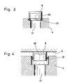
- FIG. 3 shows a fitting of a sensor 8 into the valve block 4 or between the valve block 4 and the control unit cover, which, however, is not shown in FIG. 3 is.
- the seals are here on the side of the pressure sensor is preferably cup-shaped. So this is it preferably a radial seal.
- the expansion or movement of the sensor is limited by the control unit cover 5.
Landscapes
- Physics & Mathematics (AREA)
- Electromagnetism (AREA)
- Engineering & Computer Science (AREA)
- Fluid Mechanics (AREA)
- Transportation (AREA)
- Mechanical Engineering (AREA)
- Fluid-Pressure Circuits (AREA)
- Valve Housings (AREA)
- Control Of Fluid Pressure (AREA)
Description
- Fig. 1
- eine erfindungsgemäße Ausführungsform eines Behältnisses in schematischer Darstellung,
- Fig. 2
- eine weitere erfindungsgemäße Ausführungsform eines Behältnisses in schematischer Darstellung,
- Fig. 3
- eine schematische Darstellung einer Einpassung eines Sensors auf einem Ventilblock in schematischer und vergrößerter Darstellung und
- Fig. 4
- eine schematische Darstellung einer weiteren Einpassung eines Sensors auf einen-Ventilblock.
- 1.
- Druckmittelzufuhranschluss
- 2.
- Druckmittelrücklaufanschluss
- 3.
- Ausgangsanschluss
- 4.
- Gehäuseunterteil (Ventilblock)
- 5.
- Steuergerätedeckel
- 6.
- Schraube
- 7.
- Magnetventilentlüftung
- 8.
- Drucksensor
- 9.
- Leiterplattendruchbruch
- 10.
- flexible Leitung
- 11.
- mechanische Steuer- und Regeleinheit
- 12.
- Magnetventil
- 13.
- Dichtelement
- 14.
- Mikrokontroller
- 15.
- Instrumentenverstärker
- 16.
- elektrisch beschreib- und lesbarer bzw. überschreibbarer Speicher (z. B. EE oder Flash ROM)
- 17.
- Druckmittelausgangsbohrung
- 18.
- Steuergerätedeckeldichtung
- 19.
- Leistungshalbleiter
- 20.
- Steuergerät
- 21.
- Steuergeräteschraube
- 22.
- Stecker
- 23.
- Steckerleitung
- 24.
- Rückschlagventil
- 25.
- Entlastungsbohrung
- 26.
- Entlastungsraum
- 27.
- Leiterplatte
- 28.
- Steckerdichtung
- 29.
- Messanschluss
- 30.
- Druckmittelspeicher
- 31.
- Steueranschluss
- 32.
- Deckelschraube
- 33.
- wärmeleitendes Material
- 34.
- biegesteifes Bauteil
- 35.
- Stecker
- 36.
- Signalleitung
- 39.
- flexible Leitung
- 40.
- Sensormembran
Claims (22)
- Drucksteuergerät für Fahrzeuge mit einer Steuereinrichtung (20), einem mechanischen, pneumatischen und/oder hydraulischen Element (4) und wenigstens einem Sensor (8), wobei die Steuereinrichtung (20) eine Platine (27) umfasst, die wenigstens eine Aussparung oder wenigstens ein Loch (9) für den wenigstens einen Sensor (8) aufweist, in das der wenigstens eine Sensor (8) wenigstens teilweise aufnehmbar ist, dadurch gekennzeichnet, dass der wenigstens eine Sensor (8) in der wenigstens einen Aussparung oder dem wenigstens einen Loch (9) bewegbar angeordnet ist.
- Drucksteuergerät nach Anspruch 1, dadurch gekennzeichnet, dass das Steuergerät ein Behältnis mit einem ersten und einem zweiten Behältnisteil (4,5) umfasst, wobei die Behältnisteile (4, 5) miteinander verbindbar sind und wobei das erste Behältnisteil (5) mit dem zweiten Behältnisteil (4) für wenigstens die Steuereinrichtung (20) eine im wesentlichen geschlossene Kammer bildet.
- Drucksteuergerät nach Anspruch 2, dadurch gekennzeichnet, dass das mechanische, pneumatische und/oder hydraulische Element das zweite Behältnisteil ist.
- Drucksteuergerät nach einem oder mehreren der Ansprüche 1 bis 3 dadurch gekennzeichnet, dass das hydraulische Element (4) ein Ventilblock ist.
- Drucksteuergerät nach einem oder mehreren der Ansprüche 1 bis 3, dadurch gekennzeichnet, dass das zweite Behältnisteil (4) ein Steuerventilblock für die Druckluftanlage eines Fahrzeuges ist.
- Drucksteuergerät nach einem oder mehreren der Ansprüche 1 bis 5, dadurch gekennzeichnet, dass ein biegesteifes Element vorgesehen ist.
- Drucksteuergerät nach Anspruch 6, dadurch gekennzeichnet, dass das biegesteife Element (34) ein Behältnisteil (4, 5) ist.
- Drucksteuergerät nach Anspruch 6, dadurch gekennzeichnet, dass das biegesteife Element (34) mit einem Behältnisteil (4, 5) verbindbar ist.
- Drucksteuergerät nach einem oder mehreren der Ansprüche 6 bis 8, dadurch gekennzeichnet, dass das biegesteife Element (34) zum Aufnehmen der Druckkräfte von dem wenigstens einen Sensor (8) vorgesehen ist.
- Drucksteuergerät nach einem oder mehreren der Ansprüche 1 bis 9, dadurch gekennzeichnet, dass die Signalverarbeitung des wenigstens einen Sensors (8) in der Steuereinrichtung (20) stattfindet.
- Drucksteuergerät nach einem oder mehreren der Ansprüche 1 bis 10, dadurch gekennzeichnet, dass in der Steuereinrichtung (20) Verstärker (15, 19) vorgesehen sind, die die Signale des wenigstens einen Sensors (8) verstärken.
- Drucksteuergerät nach Anspruch 11, dadurch gekennzeichnet, dass die Verstärker (15, 19) in unmittelbarer oder mittelbarer Nachbarschaft zu dem wenigstens einen Sensor (8) angeordnet sind.
- Drucksteuergerät nach einem oder mehreren der Ansprüche 1 bis 12, dadurch gekennzeichnet, dass die elektrische Verbindung (10) zwischen Sensor (8) und Steuereinrichtung (20) wenigstens teilweise über flexible Leitungen (10) geschieht.
- Drucksteuergerät nach einem oder mehreren der Ansprüche 1 bis 13, dadurch gekennzeichnet, dass im Drucksteuergerät ein Speicherelement (16) vorgesehen ist.
- Drucksteuergerät nach Anspruch 14, dadurch gekennzeichnet, dass Kalibrierwerte des wenigstens einen Sensors (8) und/oder Regelparameter oder Steuerparameter der Steuereinrichtung (20) in dem Speicherelement (16) speicherbar sind.
- Drucksteuergerät nach einem oder mehreren der Ansprüche 2 bis 15, dadurch gekennzeichnet, dass der wenigstens eine Sensor (8) in einem Bereich zwischen den beiden Behältnisteilen (4, 5) angeordnet ist.
- Drucksteuergerät nach Anspruch 16, dadurch gekennzeichnet, dass der wenigstens eine Sensor (8) von den beiden Behältnisteilen (4, 5) gehalten ist.
- Drucksteuergerät nach einem oder mehreren der Ansprüche 1 bis 17, dadurch gekennzeichnet, dass wenigstens eine Dichtung (13) vorgesehen ist, die den wenigstens einen Sensor (8) abdichtet.
- Drucksteuergerät nach Anspruch 18, dadurch gekennzeichnet, dass die Dichtung zwischen dem Druckanschluss des zweiten Behältnisteils (4) und dem Sensor (8) vorgesehen ist.
- Drucksteuergerät nach einem oder mehreren der Ansprüche 1 bis 19, dadurch gekennzeichnet, dass der Sensor (8) topfförmig ausgebildet ist.
- Drucksteuergerät nach Anspruch 20, dadurch gekennzeichnet, dass der Sensor (8) über den Rand des Topfbodens von einem Behältnisteil gehalten oder geführt ist.
- Drucksteuergerät nach Anspruch 20 und/oder 21, dadurch gekennzeichnet, dass eine Sensormembran (40) am Topfboden ausgebildet ist.
Applications Claiming Priority (3)
| Application Number | Priority Date | Filing Date | Title |
|---|---|---|---|
| DE19839843 | 1998-09-02 | ||
| DE19839843A DE19839843A1 (de) | 1998-09-02 | 1998-09-02 | Drucksteuergerät für Fahrzeuge |
| PCT/EP1999/006401 WO2000013950A1 (de) | 1998-09-02 | 1999-09-01 | Drucksteuergerät für fahrzeuge |
Publications (2)
| Publication Number | Publication Date |
|---|---|
| EP1107895A1 EP1107895A1 (de) | 2001-06-20 |
| EP1107895B1 true EP1107895B1 (de) | 2004-03-17 |
Family
ID=7879454
Family Applications (1)
| Application Number | Title | Priority Date | Filing Date |
|---|---|---|---|
| EP99944568A Expired - Lifetime EP1107895B1 (de) | 1998-09-02 | 1999-09-01 | Drucksteuergerät für fahrzeuge |
Country Status (5)
| Country | Link |
|---|---|
| US (1) | US6817247B1 (de) |
| EP (1) | EP1107895B1 (de) |
| AU (1) | AU5743399A (de) |
| DE (2) | DE19839843A1 (de) |
| WO (1) | WO2000013950A1 (de) |
Cited By (1)
| Publication number | Priority date | Publication date | Assignee | Title |
|---|---|---|---|---|
| DE102011086906B4 (de) | 2011-11-23 | 2019-08-08 | Continental Automotive Gmbh | Steuervorrichtung für ein Kraftfahrzeug |
Families Citing this family (26)
| Publication number | Priority date | Publication date | Assignee | Title |
|---|---|---|---|---|
| DE10061950C2 (de) * | 2000-12-13 | 2002-11-21 | Knorr Bremse Systeme | Elektromechanischer Bremsaktuator |
| DE10260139A1 (de) * | 2002-12-20 | 2004-07-15 | Rexroth Mecman Gmbh | Kompaktes elektropneumatisches Mehrwegeventil |
| US7798174B2 (en) * | 2003-08-20 | 2010-09-21 | Eaton Corporation | Electric fluid servo valve and method of making same |
| DE102004019483A1 (de) * | 2004-04-22 | 2005-11-10 | Daimlerchrysler Ag | Vorrichtung zur pneumatischen und elektrischen Versorgung einer Achsbaugruppe |
| DE102005023837A1 (de) * | 2005-05-24 | 2006-12-14 | Continental Teves Ag & Co. Ohg | Elektronische Regeleinheit mit Kühlung durch Ventilblock |
| DE102006020277A1 (de) * | 2006-04-27 | 2007-10-31 | Conti Temic Microelectronic Gmbh | Druckverteiler für ein Kraftfahrzeug, insbesondere für pneumatische Aktoren in Sitzen |
| DE102006044764A1 (de) * | 2006-09-20 | 2008-04-03 | Wabco Gmbh | Ventilsteuereinheit, insbesondere Vorsteuereinheit für einen Druckmodulator eines Nutzfahrzeuges |
| DE102007023345B4 (de) * | 2007-05-16 | 2013-09-12 | Knorr-Bremse Systeme für Nutzfahrzeuge GmbH | Bremsanlage für ein mit einem Anhänger pneumatisch koppelbares Nutzfahrzeug und Verfahren zum Betreiben einer solchen Bremsanlage |
| DE102007052697A1 (de) * | 2007-11-06 | 2009-05-07 | Wabco Gmbh | Magnetventileinheit für eine elektropneumatische Steuerung, insbesondere für einen Druckmodulator eines Nutzfahrzeuges |
| DE102010050580A1 (de) * | 2010-11-05 | 2012-05-10 | Wabco Gmbh | Ventileinrichtung, Bremsanlage und Fahrzeug |
| DE102011006632A1 (de) | 2011-04-01 | 2012-10-04 | Robert Bosch Gmbh | Elektronikmodul |
| DE102011006622A1 (de) | 2011-04-01 | 2012-10-04 | Robert Bosch Gmbh | Elektronikmodul sowie Verfahren zu dessen Herstellung |
| DE102012215673A1 (de) * | 2012-09-04 | 2014-03-06 | Zf Friedrichshafen Ag | Anordnung eines elektrischen Steuergeräts an eine Schaltplatte |
| DE102013015157A1 (de) * | 2013-09-11 | 2015-03-12 | Wabco Gmbh | Luftaufbereitungsanlage für die Druckluftversorgung von Nutzkraftfahrzeugen |
| DE102014010815A1 (de) * | 2014-07-23 | 2016-01-28 | Wabco Gmbh | Elektropneumatisches Regelventil |
| DE102016000760A1 (de) * | 2016-01-27 | 2017-07-27 | Siemens Aktiengesellschaft | Schaltung und Verteilerblock und aus diesen gebildete Bremssteueranordnung für Schienenfahrzeuge sowie Verteilersatz zum Konfigurieren und Verfahren zur Bildung der Bremssteueranordnung |
| DE102017211324A1 (de) * | 2017-07-04 | 2019-01-10 | Robert Bosch Gmbh | Hydraulikeinheit und Steuergerät für ein hydraulisches Bremssystem |
| DE102019129311B4 (de) * | 2019-10-30 | 2021-08-12 | Schaeffler Technologies AG & Co. KG | Hydraulischer Aktor mit bauraumsparender Integration eines Drucksensors |
| FR3111079B3 (fr) | 2020-06-04 | 2022-07-08 | Philippe Roux | Dispositif de traitement et de purification d'air par photocatalyse |
| FR3111258B3 (fr) | 2020-06-10 | 2022-07-08 | Philippe Roux | Masque facial de protection respiratoire |
| FR3114248B3 (fr) | 2020-09-21 | 2022-09-23 | Philippe Roux | Table de traitement des polluants et autonettoyante |
| FR3114517B3 (fr) | 2020-09-25 | 2022-09-23 | Philippe Roux | Dispositif de traitement et de purification d'air par photocatalyse |
| FR3115218B3 (fr) | 2020-10-20 | 2022-09-23 | Philippe Roux | Dispositif de traitement et de purification d'air par photocatalyse |
| EP4052976A1 (de) * | 2021-03-05 | 2022-09-07 | KNORR-BREMSE Systeme für Schienenfahrzeuge GmbH | Ventilgehäuse für ein regelventil und regelventil |
| ES3037066T3 (en) * | 2021-03-05 | 2025-09-26 | Knorr Bremse Systeme | Interface adapter for a control valve and control valve with an interface adapter |
| FR3122095B1 (fr) | 2021-04-22 | 2025-03-14 | Philippe Roux | Dispositif de traitement et de purification d'air par photocatalyse |
Family Cites Families (12)
| Publication number | Priority date | Publication date | Assignee | Title |
|---|---|---|---|---|
| GB9215510D0 (en) * | 1992-07-22 | 1992-09-02 | Grau Ltd | Braking systems |
| DE4232586A1 (de) | 1992-09-23 | 1994-03-24 | Mannesmann Ag | Relaisventil für fluidische Medien |
| DE4331966B4 (de) * | 1993-09-21 | 2005-01-05 | Wabco Gmbh & Co.Ohg | Steuereinrichtung |
| DE9415078U1 (de) * | 1993-09-29 | 1995-02-02 | Siemens Ag | Feuchtigkeitsdicht geschlossenes Motor-Pumpen-Aggregat, insbesondere für eine Kraftfahrzeug-Antiblockier-Bremsvorrichtung |
| DE4445125A1 (de) | 1994-12-17 | 1996-06-20 | Wabco Gmbh | Gehäuse für ein elektrisches Bauteil |
| DE19514383A1 (de) * | 1995-04-19 | 1996-10-24 | Teves Gmbh Alfred | Hydraulische Kraftfahrzeugbremsanlage mit Bremsschlupfregelung und/oder automatischem Bremseneingriff zur Antriebs- und/oder Fahrdynamikregelung |
| DE19521832A1 (de) * | 1995-06-16 | 1996-12-19 | Bosch Gmbh Robert | Druckmeßvorrichtung |
| DE19528812B4 (de) * | 1995-08-05 | 2006-12-14 | Knorr-Bremse Systeme für Nutzfahrzeuge GmbH | Aggregat für eine Fahrzeugbremsanlage |
| US5937898A (en) * | 1996-04-25 | 1999-08-17 | Eaton Corporation | Overmolded frame bus with integral pressure switch |
| AU4232397A (en) * | 1996-08-20 | 1998-03-06 | Kelsey-Hayes Company | Solenoid coil structure and interconnection |
| DE29723096U1 (de) * | 1997-03-07 | 1998-04-02 | Mannesmann Rexroth Pneumatik GmbH, 30453 Hannover | Elektropneumatisches Druckregelventil |
| US6220101B1 (en) * | 1998-02-03 | 2001-04-24 | Ssi Technologies, Inc. | Apparatus for measuring multiple pressures |
-
1998
- 1998-09-02 DE DE19839843A patent/DE19839843A1/de not_active Ceased
-
1999
- 1999-09-01 EP EP99944568A patent/EP1107895B1/de not_active Expired - Lifetime
- 1999-09-01 DE DE59908904T patent/DE59908904D1/de not_active Expired - Lifetime
- 1999-09-01 AU AU57433/99A patent/AU5743399A/en not_active Abandoned
- 1999-09-01 WO PCT/EP1999/006401 patent/WO2000013950A1/de not_active Ceased
- 1999-09-01 US US09/786,274 patent/US6817247B1/en not_active Expired - Fee Related
Cited By (1)
| Publication number | Priority date | Publication date | Assignee | Title |
|---|---|---|---|---|
| DE102011086906B4 (de) | 2011-11-23 | 2019-08-08 | Continental Automotive Gmbh | Steuervorrichtung für ein Kraftfahrzeug |
Also Published As
| Publication number | Publication date |
|---|---|
| WO2000013950A1 (de) | 2000-03-16 |
| DE19839843A1 (de) | 2000-03-09 |
| AU5743399A (en) | 2000-03-27 |
| DE59908904D1 (de) | 2004-04-22 |
| EP1107895A1 (de) | 2001-06-20 |
| US6817247B1 (en) | 2004-11-16 |
Similar Documents
| Publication | Publication Date | Title |
|---|---|---|
| EP1107895B1 (de) | Drucksteuergerät für fahrzeuge | |
| DE19936300B4 (de) | Druckerkennungsvorrichtung und Druckerkennungsvorrichtung-Anordnung hiermit | |
| EP1181505B1 (de) | Sensorbaugruppe mit einem an einer wand montierbaren gehäuse | |
| DE3629226C2 (de) | Proportionales elektrohydraulisches Drucksteuerventil | |
| EP1282544B1 (de) | Bremsvorrichtung mit integriertem drucksensormodul | |
| EP1827934B1 (de) | Elektrohydraulische druckregelvorrichtung für kraftfahrzeugbremssysteme | |
| EP0742765B1 (de) | Blockiergeschützte bremsanlage | |
| EP2687823B2 (de) | Vorrichtung zur Erfassung und Verarbeitung von Sensormesswerten und/oder zur Steuerung von Aktuatoren | |
| DE10245815B4 (de) | Druckluftsteuervorrichtung für eine elektronische Luftfederungsanlage für ein Fahrzeug | |
| DE69306520T2 (de) | Antiblockier-Bremssystem | |
| DE19528252B4 (de) | Aggregat für eine Fahrzeugbremsanlage | |
| WO2010136292A1 (de) | Steuergerät mit drucksensor | |
| DE19841334A1 (de) | Drucksensorbaugruppe | |
| EP0736429A2 (de) | Hydraulikaggregrat für eine blockiergeschützte Fahrzeugbremsanlage | |
| DE19519888A1 (de) | Hydraulikaggregat mit umlaufender Dichtung | |
| WO1996031104A1 (de) | Steuergerät für ein kraftfahrzeug | |
| DE10057912A1 (de) | Druckausgleichselement für Steckverbindungen | |
| WO1998041831A1 (de) | Messvorrichtung | |
| DE10145540A1 (de) | Drucksensorbaugruppe | |
| EP1597125B1 (de) | Drucksteuergerät | |
| DE102021205284A1 (de) | Gehäuse für elektronische Komponenten und Steuergerät | |
| DE10329489B4 (de) | Drucksteuergerät | |
| EP0342326B1 (de) | Halterbefestigung an einer druckmittelbetätigten Baugruppe | |
| DE102007026446A1 (de) | Schnell montierbares Sensorgehäuse für Sensoren mit Luftkontakt | |
| DE4432165A1 (de) | Blockiergeschützte Bremsanlage |
Legal Events
| Date | Code | Title | Description |
|---|---|---|---|
| PUAI | Public reference made under article 153(3) epc to a published international application that has entered the european phase |
Free format text: ORIGINAL CODE: 0009012 |
|
| 17P | Request for examination filed |
Effective date: 20010402 |
|
| AK | Designated contracting states |
Kind code of ref document: A1 Designated state(s): AT BE CH CY DE DK ES FI FR GB GR IE IT LI LU MC NL PT SE |
|
| AX | Request for extension of the european patent |
Free format text: AL;LT;LV;MK;RO;SI |
|
| 17Q | First examination report despatched |
Effective date: 20021011 |
|
| GRAP | Despatch of communication of intention to grant a patent |
Free format text: ORIGINAL CODE: EPIDOSNIGR1 |
|
| GRAS | Grant fee paid |
Free format text: ORIGINAL CODE: EPIDOSNIGR3 |
|
| GRAA | (expected) grant |
Free format text: ORIGINAL CODE: 0009210 |
|
| AK | Designated contracting states |
Kind code of ref document: B1 Designated state(s): DE FR GB IT SE |
|
| REG | Reference to a national code |
Ref country code: GB Ref legal event code: FG4D Free format text: NOT ENGLISH |
|
| REG | Reference to a national code |
Ref country code: SE Ref legal event code: TRGR |
|
| GBT | Gb: translation of ep patent filed (gb section 77(6)(a)/1977) |
Effective date: 20040317 |
|
| REG | Reference to a national code |
Ref country code: IE Ref legal event code: FG4D Free format text: GERMAN |
|
| REF | Corresponds to: |
Ref document number: 59908904 Country of ref document: DE Date of ref document: 20040422 Kind code of ref document: P |
|
| LTIE | Lt: invalidation of european patent or patent extension |
Effective date: 20040317 |
|
| REG | Reference to a national code |
Ref country code: IE Ref legal event code: FD4D |
|
| ET | Fr: translation filed | ||
| PLBE | No opposition filed within time limit |
Free format text: ORIGINAL CODE: 0009261 |
|
| STAA | Information on the status of an ep patent application or granted ep patent |
Free format text: STATUS: NO OPPOSITION FILED WITHIN TIME LIMIT |
|
| 26N | No opposition filed |
Effective date: 20041220 |
|
| PGFP | Annual fee paid to national office [announced via postgrant information from national office to epo] |
Ref country code: GB Payment date: 20070829 Year of fee payment: 9 |
|
| PGFP | Annual fee paid to national office [announced via postgrant information from national office to epo] |
Ref country code: IT Payment date: 20070928 Year of fee payment: 9 |
|
| GBPC | Gb: european patent ceased through non-payment of renewal fee |
Effective date: 20080901 |
|
| PG25 | Lapsed in a contracting state [announced via postgrant information from national office to epo] |
Ref country code: IT Free format text: LAPSE BECAUSE OF NON-PAYMENT OF DUE FEES Effective date: 20080901 |
|
| PG25 | Lapsed in a contracting state [announced via postgrant information from national office to epo] |
Ref country code: GB Free format text: LAPSE BECAUSE OF NON-PAYMENT OF DUE FEES Effective date: 20080901 |
|
| REG | Reference to a national code |
Ref country code: FR Ref legal event code: PLFP Year of fee payment: 18 |
|
| PGFP | Annual fee paid to national office [announced via postgrant information from national office to epo] |
Ref country code: FR Payment date: 20160922 Year of fee payment: 18 |
|
| REG | Reference to a national code |
Ref country code: FR Ref legal event code: ST Effective date: 20180531 |
|
| PG25 | Lapsed in a contracting state [announced via postgrant information from national office to epo] |
Ref country code: FR Free format text: LAPSE BECAUSE OF NON-PAYMENT OF DUE FEES Effective date: 20171002 |
|
| PGFP | Annual fee paid to national office [announced via postgrant information from national office to epo] |
Ref country code: DE Payment date: 20180924 Year of fee payment: 20 |
|
| PGFP | Annual fee paid to national office [announced via postgrant information from national office to epo] |
Ref country code: SE Payment date: 20180924 Year of fee payment: 20 |
|
| REG | Reference to a national code |
Ref country code: DE Ref legal event code: R071 Ref document number: 59908904 Country of ref document: DE |
|
| REG | Reference to a national code |
Ref country code: SE Ref legal event code: EUG |