EP1108092B1 - Unite de nettoyage - Google Patents
Unite de nettoyage Download PDFInfo
- Publication number
- EP1108092B1 EP1108092B1 EP00943809A EP00943809A EP1108092B1 EP 1108092 B1 EP1108092 B1 EP 1108092B1 EP 00943809 A EP00943809 A EP 00943809A EP 00943809 A EP00943809 A EP 00943809A EP 1108092 B1 EP1108092 B1 EP 1108092B1
- Authority
- EP
- European Patent Office
- Prior art keywords
- cylinder
- adjustment
- hydraulic
- rotary brush
- control device
- Prior art date
- Legal status (The legal status is an assumption and is not a legal conclusion. Google has not performed a legal analysis and makes no representation as to the accuracy of the status listed.)
- Expired - Lifetime
Links
Images
Classifications
-
- E—FIXED CONSTRUCTIONS
- E01—CONSTRUCTION OF ROADS, RAILWAYS, OR BRIDGES
- E01H—STREET CLEANING; CLEANING OF PERMANENT WAYS; CLEANING BEACHES; DISPERSING OR PREVENTING FOG IN GENERAL CLEANING STREET OR RAILWAY FURNITURE OR TUNNEL WALLS
- E01H1/00—Removing undesirable matter from roads or like surfaces, with or without moistening of the surface
- E01H1/02—Brushing apparatus, e.g. with auxiliary instruments for mechanically loosening dirt
- E01H1/05—Brushing apparatus, e.g. with auxiliary instruments for mechanically loosening dirt with driven brushes
- E01H1/056—Brushing apparatus, e.g. with auxiliary instruments for mechanically loosening dirt with driven brushes having horizontal axes
Definitions
- the present invention relates to a sweeping unit for Attachment to a carrier vehicle or a trailer, comprising a support frame and at least one in it their longitudinal axis rotatably, motor-driven Roller brush, the support frame having support wheels, their vertical distance from the axis of the roller brush can be changed by means of an adjustment unit, which at least one hydraulic adjusting cylinder and one Control unit includes.
- Sweeping units of the type specified above are in various designs known, for example from European patent 0372258 and German Publication 3740215. Also known Sweeping units, which are essentially generic Have structure, but differ from it in that that the hydraulic adjusting cylinder is not is set via a control unit, but rather Is part of a hydraulic control loop and that about it in addition, the support frame does not have support wheels; Such sweeping units are, for example, the German Laid-open documents 2455200 and 2821627 and the European patent applications 0189371 and 0843047 removable.
- the present invention aims at the present invention to a sweeping unit of the generic type create, with which the optimal sweeping mirror with a high degree of accuracy.
- this object solved in that with the at least one adjusting cylinder a feed cylinder is hydraulically connected, its piston or other signal transmitter with a counting and / or Position measuring device, whose signal to the control unit is switched, or a mechanical adjustment drive is connected and that with the at least an adjusting cylinder communicating hydraulic Working area has a smaller cross-sectional area than the at least one adjustment cylinder.
- the feed cylinder serves the volumetric Measuring the hydraulic fluid to the minimum an adjusting cylinder that the delivery movement of at least one adjusting cylinder from a reference position in its the optimal sweeping mirror width corresponding working position corresponds.
- the reference position can be different characteristic Positions of the roller brush relative to that to be cleaned Surface, referring to which the Control device that delivery movement of at least calculated an adjustment cylinder which is required around the roller brush in its by the optimal Sweeping mirror width marked working position bring. It is particularly preferred as a reference position the ground contact position of the roller brush and the corresponding position of the at least one Adjusting cylinder used because in this way the Bristle wear is automatically compensated (see below).
- a bypass line is particularly preferred to the feed cylinder, since the latter is only for the exact lowering of the roller brush from its ground contact position is needed in their working position. Neither when lowering the roller brush into its ground contact position you still need to lift the roller brush a volumetric determination of the at least one Adjusting cylinder supplied or out of this Volume of hydraulic fluid.
- the above explained design of the hydraulic system with a Feed cylinder results in a particularly exact Setting option for the at least one adjusting cylinder.
- the feed cylinder on the Piston of the feed cylinder is a mechanical adjustment drive acts so that the feed cylinder itself the Functions as a pump.
- the feed cylinder between a hydraulic pump and the at least one adjusting cylinder switched. He runs in this case, with the volume of the at least one adjustment cylinder supplied hydraulic fluid by the number of strokes of the feed cylinder and / or - in the case of incomplete strokes - the path of the Piston of the feed cylinder is determined.
- the Invention is a drive torque or drive power the roller brush or one coupled to it Size detecting sensor provided, the signal on the control unit is switched, the control unit being the working position corresponding to the optimal sweeping mirror width of the adjusting element as a function of the Lowering the roller brush by a sudden Rise of the sensor signal marked ground contact position of the adjusting member determined.
- the control unit includes one corresponding compensation circuit, for example in Form of a characteristic curve that shows the infeed movement, i.e. the Difference between working position and ground contact position of the adjusting element, depending on the indicates the actual diameter of the roller brush.
- the latter can be done directly from the ground contact position derive from the adjusting element, thereby on the support wheels on the surface to be cleaned - each roller brush diameter has exactly one contact with the ground of the adjusting element corresponds.
- Diameter of the roller brush which is also the position the roller brush relative to the support frame in the ground contact position the roller brush can evaluate in can be used in the same way.
- the decisive factor is that the diameter of the roller brush not - measured directly via sensors - but instead rather from the position of the roller brush at the moment of their ground contact, and thus indirectly using them of the signal from the ground contact sensor is derived.
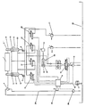
- the sweeping unit illustrated in the drawing includes a roller brush 1, which is within a support frame 2 its axis 3 rotatably and by a hydraulic motor 4 is driven.
- the support frame 2 in turn comprises two hydraulic elements forming the adjusting elements V.
- Adjustment cylinders 5 and 6 the piston rod each of the two hydraulic adjustment cylinders with each a support wheel 7 or 8 is connected.
- the - only schematically illustrated - technical-constructive Design is such that by means of Adjustment cylinders 5 and 6 the vertical distance between the support wheels 7, 8 and the axis 3 of the roller brush 1 is changeable. Such constructions are adequate known, so that for a more detailed explanation can be dispensed with.
- the sweeping unit itself is by means of a - not shown - support arrangement on a carrier vehicle suspended.
- the carrying arrangement allows lifting the sweeping unit in a transport position and lowering the sweeping unit in a working position in which the Jockey wheels 7 and 8 on the surface to be cleaned roll. This is also part of the state of the art and therefore requires no explanation at this point.
- the function of the sweeping unit is controlled by a control unit 9 controlled. This is via a control line 10 in connection with the operating point 11. Will over one corresponding switch 12 at operating point 11 Sweeping unit put into operation, so run within the hydraulics controlled by the controller 9 the following Steps from:
- valves 13 and 14 are in from their locked position their flow position switched, the control valve 15 will move from its locked position to its crossover position switched in which there are connections P and B on the one hand and A and T on the other hand connects, and the Pump 16 is started up. That way the hydraulic working spaces 17, 18 of the adjusting cylinders 5 and 6 filled with hydraulic fluid, and the Piston rods of the adjustment cylinders are under Displacement in the hydraulic work rooms 19 and 20 existing hydraulic fluid via the valve 14 and the back pressure valve 21 in the sump 22 in their maximum position extended.
- valves 27 and 28 in their Flow position switched. This way Hydraulic fluid via the pump 16 and the as before control valve switched in crossover position 15 in the hydraulic working spaces 19 and 20 of the adjusting cylinders 5 and 6. Their piston rods slowly retract, the hydraulic working rooms 17 and 18 existing hydraulic fluid via the (open) Valve 28 and the back pressure valve 21 in the sump 22nd is ousted. This leads to a gradual lowering the brush roller 1 in the direction of the to be cleaned Surface.
- the number of strokes of the feed cylinder 24 that do so are required, the roller brush 1 from its ground contact position to bring them into their working position depend in particular on the hydraulic reduction ratio between the feed cylinder 24 and the Adjusting cylinders 5 and 6.
- the piston rod of the feed cylinder 24 acts on a counter Z in the form of a pulse counter 31, which is connected to the control unit 9.
- the control unit 9 Corresponds to the number determined by the pulse counter 31 of strokes the value specified by the control unit 9, are all valves 13, 14, 27 and 28 and the Control valve 15 closed and the hydraulic pump 16 off.
- valves 13 and 14 take place 27 and 28 can be controlled. This way a fine adjustment lifting process. This allows external Interference that does not change too quickly is simple be compensated.
- the plow affects with its weight, the geometry of the vehicle frame is very strong related to the road surface and corresponding to the Sweeping level.
Landscapes
- Engineering & Computer Science (AREA)
- Architecture (AREA)
- Civil Engineering (AREA)
- Structural Engineering (AREA)
- Cleaning In General (AREA)
- Vehicle Body Suspensions (AREA)
- Cleaning Of Streets, Tracks, Or Beaches (AREA)
- Organic Low-Molecular-Weight Compounds And Preparation Thereof (AREA)
- Polarising Elements (AREA)
- Automatic Analysis And Handling Materials Therefor (AREA)
- Harvester Elements (AREA)
- Arrangement And Driving Of Transmission Devices (AREA)
Claims (6)
- Unité de balayage destinée à être installée sur un véhicule porteur ou sur une remorque, comprenant un châssis de support (2) et au moins une brosse cylindrique (1) montée rotative autour de son axe longitudinal (3) sur ledit châssis et entraínée par un moteur, le châssis de support (2) comportant des roues d'appui (7, 8), dont la distance verticale par rapport à l'axe (3) de la brosse cylindrique (1) peut être modifiée à l'aide d'une unité de réglage comprenant au moins un vérin hydraulique (5, 6) de réglage et un appareil de commande (9), caractérisée en ce qu'au vérin hydraulique (5, 6) de réglage, au nombre d'au moins un, est connecté un vérin hydraulique (24) d'alimentation, dont le piston ou un transmetteur de signal autre est relié à un dispositif de comptage et/ou de mesure de course (Z), dont le signal est envoyé à l'appareil de commande (9), ou est relié à une commande de réglage mécanique, et dont la chambre de travail (23) hydraulique communiquant avec le vérin de réglage au nombre d'au moins un présente une surface en section transversale plus petite que le vérin de réglage au nombre d'au moins un.
- Unité de balayage selon la revendication 1, caractérisée en ce que le vérin d'alimentation (24) est connecté entre une pompe hydraulique (16) et le vérin de réglage (5, 6) au nombre d'au moins un.
- Unité de balayage selon la revendication 1 ou 2, caractérisée en ce qu'il est prévu, entre la pompe hydraulique (16) et le vérin d'alimentation (24), une vanne de commutation (15) qui permet une alimentation directe du vérin de réglage (5, 6), au nombre d'au moins un, en contournant le vérin d'alimentation (24).
- Unité de balayage selon une des revendications 1 à 3, caractérisée en ce qu'il est prévu un capteur (S), qui mesure le couple d'entraínement ou la puissance d'entraínement de la brosse cylindrique (1) ou une grandeur couplée à celle-ci, dont le signal est transmis à l'appareil de commande (9), l'appareil de commande (9) déterminant la position de travail de l'organe de réglage (V) correspondant à la largeur de balayage optimale en fonction de la position de contact avec le sol de l'organe de réglage (V) caractérisée par une augmentation brusque du signal de capteur.
- Unité de balayage selon la revendication 4, caractérisée en ce qu'il est prévu un dispositif de mesure pour déterminer le diamètre de la brosse cylindrique (1), le signal de diamètre étant transmis à l'appareil de commande (9).
- Unité de balayage selon la revendication 6, caractérisée en ce qu'une courbe caractéristique pour l'avance dépendante du diamètre réel de la brosse cylindrique (1) du vérin de réglage (5, 6), au nombre d'au moins un, de sa position de contact avec le sol jusqu'à sa position de travail, est mémorisée dans l'appareil de commande (9).
Applications Claiming Priority (3)
| Application Number | Priority Date | Filing Date | Title |
|---|---|---|---|
| DE19927593A DE19927593C1 (de) | 1999-06-17 | 1999-06-17 | Kehraggregat |
| DE19927593 | 1999-06-17 | ||
| PCT/EP2000/005487 WO2000079059A1 (fr) | 1999-06-17 | 2000-06-15 | Unite de nettoyage |
Publications (2)
| Publication Number | Publication Date |
|---|---|
| EP1108092A1 EP1108092A1 (fr) | 2001-06-20 |
| EP1108092B1 true EP1108092B1 (fr) | 2004-04-21 |
Family
ID=7911512
Family Applications (1)
| Application Number | Title | Priority Date | Filing Date |
|---|---|---|---|
| EP00943809A Expired - Lifetime EP1108092B1 (fr) | 1999-06-17 | 2000-06-15 | Unite de nettoyage |
Country Status (9)
| Country | Link |
|---|---|
| US (1) | US6681433B1 (fr) |
| EP (1) | EP1108092B1 (fr) |
| AT (1) | ATE264947T1 (fr) |
| CA (1) | CA2341030A1 (fr) |
| DE (2) | DE19927593C1 (fr) |
| NO (1) | NO332295B1 (fr) |
| PL (1) | PL346044A1 (fr) |
| RU (1) | RU2250293C2 (fr) |
| WO (1) | WO2000079059A1 (fr) |
Cited By (7)
| Publication number | Priority date | Publication date | Assignee | Title |
|---|---|---|---|---|
| US7028925B2 (en) | 2003-05-14 | 2006-04-18 | Castle Rock Industries, Inc. | Spray gun for use with an all surface cleaning apparatus |
| US7533435B2 (en) | 2003-05-14 | 2009-05-19 | Karcher North America, Inc. | Floor treatment apparatus |
| USD654234S1 (en) | 2010-12-08 | 2012-02-14 | Karcher North America, Inc. | Vacuum bag |
| US8302240B2 (en) | 2009-07-29 | 2012-11-06 | Karcher North America, Inc. | Selectively adjustable steering mechanism for use on a floor cleaning machine |
| USD693529S1 (en) | 2012-09-10 | 2013-11-12 | Karcher North America, Inc. | Floor cleaning device |
| US8887340B2 (en) | 2003-05-14 | 2014-11-18 | Kärcher North America, Inc. | Floor cleaning apparatus |
| US8978190B2 (en) | 2011-06-28 | 2015-03-17 | Karcher North America, Inc. | Removable pad for interconnection to a high-speed driver system |
Families Citing this family (7)
| Publication number | Priority date | Publication date | Assignee | Title |
|---|---|---|---|---|
| US7120961B2 (en) * | 2002-09-06 | 2006-10-17 | Tennant Company | Brush wear adjustment system and method |
| DE102007023578A1 (de) * | 2007-05-21 | 2008-11-27 | Fraport Ag Frankfurt Airport Services Worldwide | Kehrvorrichtung |
| US9493921B2 (en) * | 2013-03-15 | 2016-11-15 | Oshkosh Corporation | Snow removal truck broom systems and methods |
| US12139865B2 (en) * | 2014-09-29 | 2024-11-12 | Keith E. Smith | Floating brush sweeper |
| WO2018202301A1 (fr) | 2017-05-04 | 2018-11-08 | Alfred Kärcher SE & Co. KG | Appareil de nettoyage des sols et procédé pour nettoyer la surface d'un sol |
| RU190156U1 (ru) * | 2018-12-17 | 2019-06-21 | Федеральное государственное бюджетное образовательное учреждение высшего образования "Сибирский государственный автомобильно-дорожный университет (СибАДИ)" | Коммунальная машина |
| USD907868S1 (en) | 2019-01-24 | 2021-01-12 | Karcher North America, Inc. | Floor cleaner |
Family Cites Families (11)
| Publication number | Priority date | Publication date | Assignee | Title |
|---|---|---|---|---|
| DE2455200A1 (de) * | 1974-11-21 | 1976-05-26 | Kibo Kommunalmasch Gmbh & Co | Regelungsanordnung |
| DE2821627A1 (de) * | 1978-05-18 | 1979-11-22 | Siegfried Kugelmann | Hoehenfuehrung der buerstenwalze und/oder tellerbuerste einer strassenreinigungsmaschine |
| US4525888A (en) * | 1983-09-09 | 1985-07-02 | Fmc Corporation | Maintaining constant pick-up broom pattern |
| ATE43665T1 (de) * | 1985-01-23 | 1989-06-15 | Reberle Reg Treuunternehmen Sc | Schneeraeumungsmaschine. |
| FI74504C (fi) * | 1986-12-01 | 1988-02-08 | Rahtikone Oy | Rengoeringsanordning foer vaeg, flygfaelt el.dyl. underlag. |
| EP0526907B1 (fr) | 1988-12-07 | 1994-11-30 | Bucher-Schörling GmbH | Procédé et dispositif de réglagle d'une largeur de balayage présélectionnée d'un balai rotatif cylindrique |
| SU1751252A2 (ru) * | 1989-12-05 | 1992-07-30 | И.И. Кравченко | Подвеска рабочего органа подметально-уборочной машины |
| US5295277A (en) * | 1992-12-14 | 1994-03-22 | Tennant Company | Convertible sweeper |
| US5369832A (en) | 1993-08-09 | 1994-12-06 | Hagger; Anthony R. | Bucket mounted sweeper |
| US5426805A (en) | 1993-08-24 | 1995-06-27 | Waldon, Inc. | Walk-behind self-propelled broom sweeper |
| ATE190686T1 (de) * | 1996-11-18 | 2000-04-15 | Schmidt Holding Europ Gmbh | Kehraggregat zum anbau an einem trägerfahrzeug oder einem anhänger |
-
1999
- 1999-06-17 DE DE19927593A patent/DE19927593C1/de not_active Expired - Fee Related
-
2000
- 2000-06-15 US US09/763,283 patent/US6681433B1/en not_active Expired - Fee Related
- 2000-06-15 CA CA002341030A patent/CA2341030A1/fr not_active Abandoned
- 2000-06-15 EP EP00943809A patent/EP1108092B1/fr not_active Expired - Lifetime
- 2000-06-15 WO PCT/EP2000/005487 patent/WO2000079059A1/fr not_active Ceased
- 2000-06-15 PL PL00346044A patent/PL346044A1/xx unknown
- 2000-06-15 AT AT00943809T patent/ATE264947T1/de not_active IP Right Cessation
- 2000-06-15 RU RU2001104410/11A patent/RU2250293C2/ru not_active IP Right Cessation
- 2000-06-15 DE DE50006141T patent/DE50006141D1/de not_active Expired - Lifetime
-
2001
- 2001-02-14 NO NO20010750A patent/NO332295B1/no not_active IP Right Cessation
Cited By (14)
| Publication number | Priority date | Publication date | Assignee | Title |
|---|---|---|---|---|
| US8528142B1 (en) | 2003-05-14 | 2013-09-10 | Karcher North America, Inc. | Floor treatment apparatus |
| US9015887B1 (en) | 2003-05-14 | 2015-04-28 | Kärcher North America, Inc. | Floor treatment apparatus |
| US9510721B2 (en) | 2003-05-14 | 2016-12-06 | Karcher North America, Inc. | Floor cleaning apparatus |
| US8245345B2 (en) | 2003-05-14 | 2012-08-21 | Karcher North America, Inc. | Floor treatment apparatus |
| US9192276B2 (en) | 2003-05-14 | 2015-11-24 | Karcher North America, Inc. | Floor cleaning apparatus |
| US8438685B2 (en) | 2003-05-14 | 2013-05-14 | Karcher North America, Inc. | Floor treatment apparatus |
| US8887340B2 (en) | 2003-05-14 | 2014-11-18 | Kärcher North America, Inc. | Floor cleaning apparatus |
| US9451861B2 (en) | 2003-05-14 | 2016-09-27 | Kärcher North America, Inc. | Floor treatment apparatus |
| US7533435B2 (en) | 2003-05-14 | 2009-05-19 | Karcher North America, Inc. | Floor treatment apparatus |
| US7028925B2 (en) | 2003-05-14 | 2006-04-18 | Castle Rock Industries, Inc. | Spray gun for use with an all surface cleaning apparatus |
| US8302240B2 (en) | 2009-07-29 | 2012-11-06 | Karcher North America, Inc. | Selectively adjustable steering mechanism for use on a floor cleaning machine |
| USD654234S1 (en) | 2010-12-08 | 2012-02-14 | Karcher North America, Inc. | Vacuum bag |
| US8978190B2 (en) | 2011-06-28 | 2015-03-17 | Karcher North America, Inc. | Removable pad for interconnection to a high-speed driver system |
| USD693529S1 (en) | 2012-09-10 | 2013-11-12 | Karcher North America, Inc. | Floor cleaning device |
Also Published As
| Publication number | Publication date |
|---|---|
| US6681433B1 (en) | 2004-01-27 |
| ATE264947T1 (de) | 2004-05-15 |
| WO2000079059A1 (fr) | 2000-12-28 |
| DE50006141D1 (de) | 2004-05-27 |
| NO332295B1 (no) | 2012-08-20 |
| DE19927593C1 (de) | 2001-04-19 |
| EP1108092A1 (fr) | 2001-06-20 |
| CA2341030A1 (fr) | 2000-12-28 |
| NO20010750D0 (no) | 2001-02-14 |
| NO20010750L (no) | 2001-04-11 |
| RU2250293C2 (ru) | 2005-04-20 |
| PL346044A1 (en) | 2002-01-14 |
Similar Documents
| Publication | Publication Date | Title |
|---|---|---|
| EP1108092B1 (fr) | Unite de nettoyage | |
| EP0916244B1 (fr) | Système de contrôle pour lever et baisser un instrument agricole accroché | |
| EP2498982B1 (fr) | Presse | |
| EP0507232B1 (fr) | Système de commande pour tracteur avec outil de travail tracté | |
| DE19747949C2 (de) | Vorrichtung zur Längeneinstellung eines Oberlenkers einer Anbaueinrichtung eines Traktors | |
| EP1108091B1 (fr) | Unité de nettoyage | |
| DE102004015419A1 (de) | Vorrichtung und Verfahren zur Steuerung einer Dickstoffpumpe | |
| DE102015104690A1 (de) | Landwirtschaftliche Maschine und Sicherheitsverfahren | |
| DE2455200A1 (de) | Regelungsanordnung | |
| EP2025215A1 (fr) | Machine de répartition de semences et/ou d'engrais | |
| DE4214109C2 (de) | Feststoffpumpe | |
| DE2154631C3 (de) | Überlastungsschutzvorrichtung für einen Ladekran | |
| DE29507623U1 (de) | Hydraulische Entlastungsvorrichtung für Anbaugeräte | |
| DE3334656A1 (de) | Einrichtung zum auswechseln eines mit einem hilfsrahmen verbundenen fahrzeugaufbaues gegen einen anderen fahrzeugaufbau | |
| DE3412068C2 (fr) | ||
| EP0843047B1 (fr) | Unité de balayage pour le montage sur un véhicule ou une remorque | |
| DE4123836C1 (en) | Suspension system for road sweeping equipment - has cylinders connected to roller with pistons to control vertical motion | |
| EP0972947B1 (fr) | Système de bras à brosses d'un véhicule de lavage de tunnels | |
| DE2903408A1 (de) | Verfahren zum drehen eines drehpfluges mittels einer hydraulischen drehvorrichtung und nach dem verfahren arbeitende drehvorrichtung | |
| AT390348B (de) | Verfahren zur steuerung der eindringtiefe von bodenbearbeitungsgeraeten, steueranordnung zu dessen durchfuehrung und bodenbearbeitungsgeraet | |
| DE2805302C3 (de) | Ladewerk für MüUpreßwagen | |
| DE9207016U1 (de) | Feststoffpumpe | |
| DE1759622C (de) | Vornchtung zum Heben, Senken und Teilentlasten der Trageinheit fur eine dann drehbar gelagerte Besenwalze einer Kehrmaschine | |
| DE19734116C1 (de) | Streugerät | |
| DE1555685C (de) | Vorrichtung zum Anheben und Absenken einer Achse eines Doppelachsaggregates fur Fahrzeuge |
Legal Events
| Date | Code | Title | Description |
|---|---|---|---|
| PUAI | Public reference made under article 153(3) epc to a published international application that has entered the european phase |
Free format text: ORIGINAL CODE: 0009012 |
|
| AK | Designated contracting states |
Kind code of ref document: A1 Designated state(s): AT BE CH CY DE DK ES FI FR GB GR IE IT LI LU MC NL PT SE |
|
| AX | Request for extension of the european patent |
Free format text: AL;LT;LV;MK;RO;SI |
|
| 17P | Request for examination filed |
Effective date: 20010517 |
|
| GRAP | Despatch of communication of intention to grant a patent |
Free format text: ORIGINAL CODE: EPIDOSNIGR1 |
|
| GRAS | Grant fee paid |
Free format text: ORIGINAL CODE: EPIDOSNIGR3 |
|
| GRAA | (expected) grant |
Free format text: ORIGINAL CODE: 0009210 |
|
| AK | Designated contracting states |
Kind code of ref document: B1 Designated state(s): AT BE CH CY DE DK ES FI FR GB GR IE IT LI LU MC NL PT SE |
|
| PG25 | Lapsed in a contracting state [announced via postgrant information from national office to epo] |
Ref country code: IE Free format text: LAPSE BECAUSE OF FAILURE TO SUBMIT A TRANSLATION OF THE DESCRIPTION OR TO PAY THE FEE WITHIN THE PRESCRIBED TIME-LIMIT Effective date: 20040421 Ref country code: CY Free format text: LAPSE BECAUSE OF FAILURE TO SUBMIT A TRANSLATION OF THE DESCRIPTION OR TO PAY THE FEE WITHIN THE PRESCRIBED TIME-LIMIT Effective date: 20040421 Ref country code: NL Free format text: LAPSE BECAUSE OF FAILURE TO SUBMIT A TRANSLATION OF THE DESCRIPTION OR TO PAY THE FEE WITHIN THE PRESCRIBED TIME-LIMIT Effective date: 20040421 |
|
| REG | Reference to a national code |
Ref country code: GB Ref legal event code: FG4D Free format text: NOT ENGLISH |
|
| REG | Reference to a national code |
Ref country code: SE Ref legal event code: TRGR |
|
| REG | Reference to a national code |
Ref country code: CH Ref legal event code: NV Representative=s name: ISLER & PEDRAZZINI AG Ref country code: CH Ref legal event code: EP |
|
| GBT | Gb: translation of ep patent filed (gb section 77(6)(a)/1977) |
Effective date: 20040421 |
|
| REG | Reference to a national code |
Ref country code: IE Ref legal event code: FG4D Free format text: GERMAN |
|
| REF | Corresponds to: |
Ref document number: 50006141 Country of ref document: DE Date of ref document: 20040527 Kind code of ref document: P |
|
| PG25 | Lapsed in a contracting state [announced via postgrant information from national office to epo] |
Ref country code: LU Free format text: LAPSE BECAUSE OF NON-PAYMENT OF DUE FEES Effective date: 20040615 |
|
| PG25 | Lapsed in a contracting state [announced via postgrant information from national office to epo] |
Ref country code: BE Free format text: LAPSE BECAUSE OF NON-PAYMENT OF DUE FEES Effective date: 20040630 Ref country code: MC Free format text: LAPSE BECAUSE OF NON-PAYMENT OF DUE FEES Effective date: 20040630 |
|
| PG25 | Lapsed in a contracting state [announced via postgrant information from national office to epo] |
Ref country code: GR Free format text: LAPSE BECAUSE OF FAILURE TO SUBMIT A TRANSLATION OF THE DESCRIPTION OR TO PAY THE FEE WITHIN THE PRESCRIBED TIME-LIMIT Effective date: 20040721 Ref country code: DK Free format text: LAPSE BECAUSE OF FAILURE TO SUBMIT A TRANSLATION OF THE DESCRIPTION OR TO PAY THE FEE WITHIN THE PRESCRIBED TIME-LIMIT Effective date: 20040721 |
|
| PG25 | Lapsed in a contracting state [announced via postgrant information from national office to epo] |
Ref country code: ES Free format text: LAPSE BECAUSE OF FAILURE TO SUBMIT A TRANSLATION OF THE DESCRIPTION OR TO PAY THE FEE WITHIN THE PRESCRIBED TIME-LIMIT Effective date: 20040801 |
|
| LTIE | Lt: invalidation of european patent or patent extension |
Effective date: 20040421 |
|
| NLV1 | Nl: lapsed or annulled due to failure to fulfill the requirements of art. 29p and 29m of the patents act | ||
| ET | Fr: translation filed | ||
| REG | Reference to a national code |
Ref country code: IE Ref legal event code: FD4D |
|
| BERE | Be: lapsed |
Owner name: SCHMIDT HOLDING G.M.B.H. Effective date: 20040630 Owner name: PATRIA VAMMAS OY Effective date: 20040630 |
|
| PLBE | No opposition filed within time limit |
Free format text: ORIGINAL CODE: 0009261 |
|
| STAA | Information on the status of an ep patent application or granted ep patent |
Free format text: STATUS: NO OPPOSITION FILED WITHIN TIME LIMIT |
|
| 26N | No opposition filed |
Effective date: 20050124 |
|
| PGFP | Annual fee paid to national office [announced via postgrant information from national office to epo] |
Ref country code: AT Payment date: 20050421 Year of fee payment: 6 |
|
| PGFP | Annual fee paid to national office [announced via postgrant information from national office to epo] |
Ref country code: GB Payment date: 20050603 Year of fee payment: 6 |
|
| PGFP | Annual fee paid to national office [announced via postgrant information from national office to epo] |
Ref country code: FR Payment date: 20050621 Year of fee payment: 6 |
|
| PGFP | Annual fee paid to national office [announced via postgrant information from national office to epo] |
Ref country code: FI Payment date: 20050623 Year of fee payment: 6 |
|
| PG25 | Lapsed in a contracting state [announced via postgrant information from national office to epo] |
Ref country code: GB Free format text: LAPSE BECAUSE OF NON-PAYMENT OF DUE FEES Effective date: 20060615 Ref country code: AT Free format text: LAPSE BECAUSE OF NON-PAYMENT OF DUE FEES Effective date: 20060615 Ref country code: FI Free format text: LAPSE BECAUSE OF NON-PAYMENT OF DUE FEES Effective date: 20060615 |
|
| PGFP | Annual fee paid to national office [announced via postgrant information from national office to epo] |
Ref country code: CH Payment date: 20060627 Year of fee payment: 7 |
|
| PGFP | Annual fee paid to national office [announced via postgrant information from national office to epo] |
Ref country code: IT Payment date: 20060630 Year of fee payment: 7 |
|
| GBPC | Gb: european patent ceased through non-payment of renewal fee |
Effective date: 20060615 |
|
| REG | Reference to a national code |
Ref country code: FR Ref legal event code: ST Effective date: 20070228 |
|
| REG | Reference to a national code |
Ref country code: CH Ref legal event code: PCAR Free format text: ISLER & PEDRAZZINI AG;POSTFACH 1772;8027 ZUERICH (CH) |
|
| PG25 | Lapsed in a contracting state [announced via postgrant information from national office to epo] |
Ref country code: PT Free format text: LAPSE BECAUSE OF NON-PAYMENT OF DUE FEES Effective date: 20040921 |
|
| REG | Reference to a national code |
Ref country code: CH Ref legal event code: PL |
|
| PG25 | Lapsed in a contracting state [announced via postgrant information from national office to epo] |
Ref country code: CH Free format text: LAPSE BECAUSE OF NON-PAYMENT OF DUE FEES Effective date: 20070630 Ref country code: LI Free format text: LAPSE BECAUSE OF NON-PAYMENT OF DUE FEES Effective date: 20070630 Ref country code: FR Free format text: LAPSE BECAUSE OF NON-PAYMENT OF DUE FEES Effective date: 20060630 |
|
| PGFP | Annual fee paid to national office [announced via postgrant information from national office to epo] |
Ref country code: SE Payment date: 20090623 Year of fee payment: 10 |
|
| PG25 | Lapsed in a contracting state [announced via postgrant information from national office to epo] |
Ref country code: IT Free format text: LAPSE BECAUSE OF NON-PAYMENT OF DUE FEES Effective date: 20070615 |
|
| EUG | Se: european patent has lapsed | ||
| PG25 | Lapsed in a contracting state [announced via postgrant information from national office to epo] |
Ref country code: SE Free format text: LAPSE BECAUSE OF NON-PAYMENT OF DUE FEES Effective date: 20100616 |
|
| PGFP | Annual fee paid to national office [announced via postgrant information from national office to epo] |
Ref country code: DE Payment date: 20170825 Year of fee payment: 18 |
|
| REG | Reference to a national code |
Ref country code: DE Ref legal event code: R119 Ref document number: 50006141 Country of ref document: DE |
|
| PG25 | Lapsed in a contracting state [announced via postgrant information from national office to epo] |
Ref country code: DE Free format text: LAPSE BECAUSE OF NON-PAYMENT OF DUE FEES Effective date: 20190101 |