EP1108143B1 - Trockenverdichtende schraubenspindelpumpe - Google Patents
Trockenverdichtende schraubenspindelpumpe Download PDFInfo
- Publication number
- EP1108143B1 EP1108143B1 EP99941399A EP99941399A EP1108143B1 EP 1108143 B1 EP1108143 B1 EP 1108143B1 EP 99941399 A EP99941399 A EP 99941399A EP 99941399 A EP99941399 A EP 99941399A EP 1108143 B1 EP1108143 B1 EP 1108143B1
- Authority
- EP
- European Patent Office
- Prior art keywords
- rotor
- dry
- front face
- cooling medium
- spindles
- Prior art date
- Legal status (The legal status is an assumption and is not a legal conclusion. Google has not performed a legal analysis and makes no representation as to the accuracy of the status listed.)
- Expired - Lifetime
Links
Images


Classifications
-
- F—MECHANICAL ENGINEERING; LIGHTING; HEATING; WEAPONS; BLASTING
- F04—POSITIVE - DISPLACEMENT MACHINES FOR LIQUIDS; PUMPS FOR LIQUIDS OR ELASTIC FLUIDS
- F04C—ROTARY-PISTON, OR OSCILLATING-PISTON, POSITIVE-DISPLACEMENT MACHINES FOR LIQUIDS; ROTARY-PISTON, OR OSCILLATING-PISTON, POSITIVE-DISPLACEMENT PUMPS
- F04C18/00—Rotary-piston pumps specially adapted for elastic fluids
- F04C18/08—Rotary-piston pumps specially adapted for elastic fluids of intermeshing-engagement type, i.e. with engagement of co-operating members similar to that of toothed gearing
- F04C18/082—Details specially related to intermeshing engagement type pumps
- F04C18/084—Toothed wheels
-
- F—MECHANICAL ENGINEERING; LIGHTING; HEATING; WEAPONS; BLASTING
- F04—POSITIVE - DISPLACEMENT MACHINES FOR LIQUIDS; PUMPS FOR LIQUIDS OR ELASTIC FLUIDS
- F04C—ROTARY-PISTON, OR OSCILLATING-PISTON, POSITIVE-DISPLACEMENT MACHINES FOR LIQUIDS; ROTARY-PISTON, OR OSCILLATING-PISTON, POSITIVE-DISPLACEMENT PUMPS
- F04C18/00—Rotary-piston pumps specially adapted for elastic fluids
- F04C18/08—Rotary-piston pumps specially adapted for elastic fluids of intermeshing-engagement type, i.e. with engagement of co-operating members similar to that of toothed gearing
- F04C18/12—Rotary-piston pumps specially adapted for elastic fluids of intermeshing-engagement type, i.e. with engagement of co-operating members similar to that of toothed gearing of other than internal-axis type
- F04C18/14—Rotary-piston pumps specially adapted for elastic fluids of intermeshing-engagement type, i.e. with engagement of co-operating members similar to that of toothed gearing of other than internal-axis type with toothed rotary pistons
- F04C18/16—Rotary-piston pumps specially adapted for elastic fluids of intermeshing-engagement type, i.e. with engagement of co-operating members similar to that of toothed gearing of other than internal-axis type with toothed rotary pistons with helical teeth, e.g. chevron-shaped, screw type
-
- F—MECHANICAL ENGINEERING; LIGHTING; HEATING; WEAPONS; BLASTING
- F04—POSITIVE - DISPLACEMENT MACHINES FOR LIQUIDS; PUMPS FOR LIQUIDS OR ELASTIC FLUIDS
- F04C—ROTARY-PISTON, OR OSCILLATING-PISTON, POSITIVE-DISPLACEMENT MACHINES FOR LIQUIDS; ROTARY-PISTON, OR OSCILLATING-PISTON, POSITIVE-DISPLACEMENT PUMPS
- F04C27/00—Sealing arrangements in rotary-piston pumps specially adapted for elastic fluids
- F04C27/008—Sealing arrangements in rotary-piston pumps specially adapted for elastic fluids for other than working fluid, i.e. the sealing arrangements are not between working chambers of the machine
- F04C27/009—Shaft sealings specially adapted for pumps
-
- F—MECHANICAL ENGINEERING; LIGHTING; HEATING; WEAPONS; BLASTING
- F04—POSITIVE - DISPLACEMENT MACHINES FOR LIQUIDS; PUMPS FOR LIQUIDS OR ELASTIC FLUIDS
- F04C—ROTARY-PISTON, OR OSCILLATING-PISTON, POSITIVE-DISPLACEMENT MACHINES FOR LIQUIDS; ROTARY-PISTON, OR OSCILLATING-PISTON, POSITIVE-DISPLACEMENT PUMPS
- F04C29/00—Component parts, details or accessories of pumps or pumping installations, not provided for in groups F04C18/00 - F04C28/00
- F04C29/02—Lubrication; Lubricant separation
- F04C29/025—Lubrication; Lubricant separation using a lubricant pump
-
- F—MECHANICAL ENGINEERING; LIGHTING; HEATING; WEAPONS; BLASTING
- F04—POSITIVE - DISPLACEMENT MACHINES FOR LIQUIDS; PUMPS FOR LIQUIDS OR ELASTIC FLUIDS
- F04C—ROTARY-PISTON, OR OSCILLATING-PISTON, POSITIVE-DISPLACEMENT MACHINES FOR LIQUIDS; ROTARY-PISTON, OR OSCILLATING-PISTON, POSITIVE-DISPLACEMENT PUMPS
- F04C29/00—Component parts, details or accessories of pumps or pumping installations, not provided for in groups F04C18/00 - F04C28/00
- F04C29/04—Heating; Cooling; Heat insulation
Definitions
- the object of the present invention is to design a vacuum pump that is as simple and robust as possible, as well as particularly inexpensive and compact, in order to achieve significant improvements over the current state of the art thanks to the dry method of working in vacuum generation.
- both displacement spindles are hollow throughout and a permanent coolant flow, preferably oil, is passed directly through each of the two displacement cylinders in order to continuously and reliably dissipate the amount of heat occurring during vacuum generation from each spindle rotor.
- a permanent coolant flow preferably oil
- the better heat transfer coefficient is achieved with this rotor heat transport between the displacement rotor material and the Cooling medium compared with a smaller rotor cylinder inner surface the larger heat-absorbing outer surface of the displacement rotor with a lower heat transfer coefficient between the rotor material and the pumped medium is used in favor of balanced rotor thermals, so that after a simple thermodynamic interpretation absorbed and dissipated rotor heat in the desired balance are.
- the temperature level can be favorable for each application by setting and controlling the amount of coolant become. It is essential that the amount of coolant is evenly distributed on both displacement rotors by appropriate monitoring devices to watch out for.
- the inner rotor bore preferably additionally with a direction of rotation
- Internal conveyor threads run to both the inner Heat exchange surface between the displacer and the cooling medium as also the coolant flow through appropriate thread orientation improve.
- the direction of rotation of each displacement rotor is according to the Pump delivery direction clearly fixed, so that the internal thread orientation the displacement rotor excavation can be carried out in such a way that accordingly this fixed direction of rotor rotation its coolant flow is supported and strengthened.
- the entire coolant flow is preferably with its own pressure-generating Defined pump realized, so that this cooling medium (preferably Oil) not only specifically through the displacer cavities, storage, more specifically Sealing elements as well as synchronization and drive teeth is guided, but at the same time on the housing if possible with gravity support can be specifically directed to the recorded To release heat again.
- This in a closed cycle constantly repeating process is supported by the well known additional external possibilities for heat exchange, starting with one ribbed housing, the suitable housing material, as well as the simple Fan, up to the additional heat exchanger connection, which is directly from the Coolant flow is flowed through.
- your own pressure-generating Pump can alternatively and especially for smaller machine sizes kinetic energy of the rotor rotation can be exploited by using the displacement rotor directly connected an own oil pump according to the known principles becomes.
- each displacement rotor 1, 2 immediately at the front at least on the coolant-discharging rotor side in capsule-like Rotor elements 4 is mounted, through which on one side Cooling medium in the desired amount directly into each of the continuous Displacement rotor bores supplied and removed again at the other end becomes.
- the rotor bearing 5 is designed such that the bearing inner ring supported on a housing-fixed pin 6 while the Bearing outer ring in the capsule-like rotor element 4 permanently with the Displacement rotor 1 or 2 also rotates.
- this form of rotor bearing can also be dispensed with at least on one side be by the according to the accompanying representation in Fig. 3
- Inner bearing ring of the rotor bearing 5 is located on the displacement rotor and the Bearing outer ring is supported on the side part 7 fixed to the housing.
- Rotor cooling can be realized by the housing-fixed pin 6 wide protrudes into the displacement rotor bore and both the inner bearing rings carries as well as the coolant supply 8 takes over.
- the stiffness of this one-sided support is low Radial loads on a screw spindle vacuum pump can be easily implemented, by the lower bearing 5a having a larger bearing inner diameter has at the same time the higher axial forces due to the working pressure difference of the pumped medium.
- the upper bearing 5b for example, can also be screw machines as a compact radial bearing or as an oil-lubricated plain bearing be carried out.
- this cooling stream preferably oil
- This branching in the coolant supply 8 takes place, for example via a shoulder 17 in the conical rotor insert 16 or via bores 10 in the rotor elements, as well as by means of oil overflow of the collecting channels 18 and also via spray oil when removing the oil channel via a pitot tube 19, the necessary amount of lubricant by dimensioning these elements can be set favorably.
- the supply is preferably carried out via the lubricant distribution holes 10 or via the targeted channel overflow 24 the Siphon shaft seal 22 - see later explanation.
- this object is achieved by the double-flow design known in screw pumps, so that the gas entry no longer takes place on the end face, but within the longitudinal side of the rotor, and the outlet-side pressure adjusts to the atmospheric pressure on each end face of the rotor.
- both sides of the displacer pair are designed with the same spindle delivery thread, so that the gas flow to be delivered can be divided evenly. This advantageously reduces the necessary center distance and thus the overall size, while the overall length increases, whereby the overall manufacturing costs of such a machine will be reduced.
- a displacement pair part (with the vertical direction of delivery the upper part) can only be designed as a simple leakage delivery thread in order to only return the internal gas backflow due to the pressure difference between the pump inlet and outlet side ,
- This leakage conveying thread can be implemented both by mutual rotor engagement with the other displacement spindle or separately as a simple conveying thread in the solid cylinder fixed to the housing, comparable to the so-called Golubev thread.
- the Dispensing with a rotor bearing on the suction side offers the advantages of today's drying compressors Screw spindle vacuum pumps taken over and at the same time the disadvantages with regard to the considerable axial forces for the rotor bearing avoided.
- the coolant preferably oil
- the coolant must be permanent and safe introduced into the rotating rotor cylinder inner surface and finally be discharged again.
- This oil feed takes place on the housing-fixed pin to the rotor shaft via a special conical insert 16 in the rotor bore with a suitable Counterpart (for example as a bevel) on the housing Pin to ensure an even oil distribution as possible.
- a suitable Counterpart for example as a bevel
- this rotating insert 16 receives such a paragraph 17 in its Taper inclination that the coolant / lubricant supplied via 8 pin-side hosed on the cone insert 16 to the desired small part is and in this way for the lubrication of the rotor bearing 5 and for siphon supply 20 arrives.
- the much larger oil flow is groove-shaped Cutouts in the insert 16 in the displacement bore conducted to dissipate the compression loss heat.
- this rotating siphon can only act as a dynamic seal, becomes a contacting shaft seal as a static seal 27, for example the known radial shaft sealing ring, such as in the rotating one Rotor element used that it seals securely at standstill and when rotation begins, when the siphon seal does its sealing job takes over, his sealing lip begins due to the centrifugal force take off, so that at the same time an optimal wear protection arises.
- the oil leakage is advantageously not only for bearing lubrication, but at the same time both for feeding the sealing siphon as well as for lubrication of the synchronization teeth used.
- this siphon rotates the slim sealing washer and the delimiting siphon side walls are fixed to the housing. This ensures the necessary lubrication of the synchronization teeth particularly favorable due to the targeted channel overflow the siphon pump chamber shaft seal in the gear meshing area of the Synchronization gear by placing the siphon side wall in exactly this Area is withdrawn.
- This form of lower shaft seal with simultaneous supply of the synchronization teeth 1 is of course also for the flying bearing design according to FIG. 2 transferable and suitable.
- Such a screw vacuum pump is preferably with vertical displacement rotor pair, but in any case the pump housing surrounding the displacement rotors is designed so that the possibly required liquid drain supports gravity from the pump delivery chamber is guaranteed at all times by the The outlet of the pumped medium is always at the geodetically lowest position located.
- the two displacement spindles are synchronized using a simple, well-known oil-lubricated spur gear.
- the drive with the necessary increase in speed preferably takes place via a larger spur gear, directly or via a simple countershaft directly drives this synchronization stage.
- the drive motor will then preferably arranged parallel to the spindle pump. However, it can the drive motor not only for smaller machines in direct extension a displacement spindle are arranged, and the speed increase happens by means of frequency converter.
- this gradation now takes place through the different combination of two factors of the internal gradation as a change in the delivery chamber volumes as shown in FIG. 2.
- the one value is between 1.5 and 2.2 as a factor, preferably around 1.85 and becomes Technically implemented by continuously reducing the spindle pitch by exactly this factor while the outer diameter of the displacement rotor remains the same.
- the second value is between a minimum of 2.0 and a maximum of 9.0 as a factor, preferably around 4.0 to 6.0, and is implemented technically by changing the volume of a working / delivery chamber by exactly this factor by a sudden change in the rotor geometry parameters is reduced, the displacement rotor outer diameter and thus the tooth groove height and, for larger values, the rotor spindle pitch to achieve this factor being reduced accordingly in combination.
- each spindle rotor 2 conveyor threaded portions wherein the one part is designed with a continuous change in gradient (factor of about 1.85 in order to reduce the volume of a working / delivery chamber) at the same rotor outer diameter, while abruptly in the immediately subsequent second rotor spindle portion the
- the volume of the working / delivery chamber is reduced by a factor of preferably between 4 and 6 by abruptly reducing the tooth height and possibly also the spindle pitch.
- the Displacement section with the previously constant working / delivery chamber volume with a constant rotor outer diameter with a continuous Reduction of the rotor pitch is carried out. It should this change in slope value is also between 1.2 and 2.2, preferably at about 1.85. However, for some pump applications the possible overcompression in the rotor section with continuous Change in slope at a value of about 1.85 may be undesirable, so that this invention also proposes this preferred value to be distributed equally over both rotor sections, i.e. both displacer sections with a continuous change in slope from about 1.36 to 1.40 to execute.
- the change in slope should also include a non-linear one
- a non-linear one follow the course, for example a quadratic function, so that the slope change initially (from the suction side) rises more gently and later stronger again towards the end of the first rotor section increased so that the quotient from the final to the initial slope the desired Value reached, which is between 1.2 and 1.8, preferably about 1.5 is suggested.
- the pressure curve is longitudinal of the displacement rotor cylinder between the inlet and outlet position with a seen from the inlet side, the pressure rise is as gentle as possible and that the critical transfer pressure between the two rotor sections both the compressibility in terms of its size and its position this vacuum pump is not affected too much. Therefore the first rotor section must have a sufficient length, that is have at least a number of steps of 2.0.
- the embodiment of the inner gradation is shown by way of example, by the slope varies continuously in the first conveying screw portion by a value M 1 to a value of M2, so that finally the volume reaches a working / delivery chamber the value V 1 , In the transition between the two conveyor thread sections, this volume V 1 is abruptly reduced to the value V 2 at least by reducing the outer rotor diameter. In the second conveyor thread section, the spindle pitch is then continuously reduced from the value m1 to the value m2.
- profile flank profile be designed as follows:
- the profile flanks are usually for both spindle displacement rotors identical in the forehead section and mathematically correspond to the known course of the cycloid.
- this has the disadvantage that on the one hand the circular line of engagement is not close enough to the cutting edge of the two Housing inner cylinder surfaces and on the other hand the profile rolling according to the gearing law even with minor Changes in the center distance, for example due to manufacturing deviations or temperature differences, is very sensitive because of the Cycloids in the area of the pitch circle transition in the first derivative of the Profile slope has a kink, so discontinuous in the following derivation is.
- the profile flank course in the area of the pitch circle mathematically is designed as an involute, i.e. in the area of the pitch circle with a profile slope change of -1 as a value. Furthermore, it is proposed that the line of engagement is closer to the housing cut edge of the two Inner cylinder surfaces is brought up so that the internal gas leak there is reduced. In addition to improving the sealing effect between the two rotor spindle flanks and thus the raised one Compression still suggested that the flank run out composed of several contours in engagement at the same time becomes. For this purpose, the pitch point positions according to the gearing law of the corresponding profile flanks, one double overlay is usually sufficient.
- the first rotor section primarily as Volume (more precisely: pumping speed) generator can be seen during the second rotor section as the pressure generator the larger absolute pressure difference must cope with.
- gas cooling furthermore the pre-admission is used.
- the still closed working / delivery chamber supplied cool gas which due to the prevailing pressure difference with the fluid mixes and both to lower the gas temperature in the working / delivery chamber also leads to a reduction in pressure differences at the moment the opening of the working / delivery chamber on the outlet side, so that reduces the noise caused by gas pulsations.
- outlet edges should also be used accordingly be gently designed by the opening behavior of each Working / conveying chamber follows a function dependent on the angle of rotation and each abrupt change in cross-section when opening the work / conveyor chambers is avoided.
- Ventilation wheels 29 on the outlet-side shaft end according to the enclosed 1 shows the pressure pulsations and gas column vibrations effectively disrupt and degrade.
- FIG. 1 shows a longitudinal section through a twin-shaft pump according to the invention with rotor bearings on both sides, continuous spindle rotor cooling and the siphon shaft sealing systems on both sides.
- the spur gear teeth 11 are connected in a rotationally fixed manner to these spindle rotors 1, 2 by means of clamping elements 31 for exact adjustment of the synchronization for both displacement spindles.
- FIG. 2 shows a longitudinal section through the dry-compressing screw pump with an exemplary design of the rotor gradation and, for a displacement spindle, the flying rotor bearing on the fixed journal 6 including the coolant / lubricant supply 8.
- FIG 3 shows the possible rotor bearing 5 with the bearing outer ring and the bearing inner ring on the rotor shaft including the synchronization toothing 11 for the feed side of the coolant / lubricant.
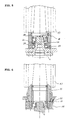
- Fig. 4 shows a particularly space-saving design for the outlet side in order to minimize the cross-sectional changes on the outlet side for the gas outlet of the pumped medium, by the rotor bearing 5 being carried out directly on the housing-fixed pin 6 and long sealing paths in without synchronization teeth, which is shifted to the other rotor end face Labyrinth shape with sealing gas option 32 can be realized.
- the coolant / lubricant is removed from the displacement cavity via the collecting trough 18 and the stationary pitot tube 19 engaging therein.
- the spray oil is sufficient for bearing lubrication during this removal process.
- Fig. 5 shows similar to the representation in Fig. 4, the outlet-side rotor bearing 5 in the capsule-like rotor extension on the housing-fixed pin 6 with rotating siphon seal 20 and standing sealing disc 21 and downstream radial shaft sealing ring 27.
- the synchronization toothing is to be provided on the other end face of the rotor, so that best possible space design conditions can be achieved for the delivery medium outlet design.
- Fig. 6 shows a modification to the representation in Fig. 1 for the outlet-side rotor face another form for fastening the synchronization toothing 11 on the rotor spindle 1, 2, the rotor bearing 5 advantageously being carried out directly in the extended displacement spindle.
- the dry-compressing screw pump is a two-shaft displacement machine to convey and compress gases with a parallel arranged rotor spindle pair 1, 2 in a closed scoop space 3 with inlet and outlet, both rotor spindles hollow inside are and a coolant / lubricant in these rotor hollows constantly is fed in and out.
- a parallel arranged rotor spindle pair 1, 2 in a closed scoop space 3 with inlet and outlet, both rotor spindles hollow inside are and a coolant / lubricant in these rotor hollows constantly is fed in and out.
- At least on the rotor timing side with the Coolant / lubricant discharge are essentially capsule-like Rotor elements 4 are provided.
- the sliding or rolling bearings 5 for these rotor faces are supported on the one hand on the inner wall of this capsule-like Rotor elements and on the other hand on a protruding into this capsule, resting pin 6 from.
- the coolant / lubricant is advantageously used constantly fed into these rotor cavities on one rotor side and continuously discharged on the other side of the rotor, the feed 8 of the Coolant / lubricant in particular on the housing-fixed pin 6 can.
- the feed 8 of the Coolant / lubricant in particular on the housing-fixed pin 6 can.
- the inner rotor bores are additional with such a direction of rotation-oriented internal conveyor thread 12, that according to the specified direction of rotation of each displacement rotor its coolant flow is supported.
- the surfaces of the inner rotor bore be carried out in the same way as the dissipation of the compression loss heat requires.
- the coolant / lubricant flow is advantageously provided by a separate pressure-generating one Pump 9 realized.
- the coolant / lubricant flow energetically through the displacement rotors with its own oil pump be generated.
- the temperature level be specifically set and regulated.
- the Coolant quantity per displacer rotor monitored and for both displacer rotors be set immediately.
- the coolant / lubricant is used for heat exchange advantageously bypassed the pump housing.
- the rotor bearing is advantageously carried out on the inlet side of the cooling / Lubricant on the outer bearing ring in the side part 7.
- Fixed with one-sided, flying rotor bearing one fixed to the housing Pin 6 into the corresponding displacement bore and carries both Rotor bearing inner rings.
- the housing-fixed pin 6 with one-sided, flying rotor bearing preferably the coolant supply 8.
- the axial forces due to the working pressure difference with one-sided (flying) Rotor bearing advantageously accommodates the rotor bearing 5a closer to the support and is carried out with a larger bearing inner ring.
- the rotor bearing further from the support 5b designed as a radial compact bearing (needle bearing, plain bearing) become.
- Both sides of the displacement pair can be designed with the same spindle feed thread are. Furthermore, it is also possible to use a displacement pair side simple leakage conveyor thread 25 to perform.
- Centrifugal shaft seals are advantageous for sealing the shaft bushings used. Furthermore, a seal is also by means of a narrow, housing-fixed sealing plate 21 possible, which rotates in a Siphon 20 engages, which is firmly connected to the displacement spindle 1, 2 is.
- the rotating siphon 20 contains its sealing liquid from a partial flow of the coolant / lubricant for positive rotor cooling receives.
- the rotating siphon 20 may have its sealing liquid also from the coolant / lubricant flow of the rotor bearing receive.
- the liquid and heat dissipation for the rotating Siphon 20 can advantageously be fixed to the sealing disk 21 Pitot tube 26 take place.
- the shaft sealing ring 27 is preferably designed such that that before reaching the operating speed, the sealing lip due to the centrifugal force takes off. For sealing, it is also advantageous if on long sealing paths with sealing gas option and leakage return threads can be realized.
- the coolant / lubricant is after flowing through the rotor inner surfaces advantageously caught in at least one collecting trough 18.
- there can the coolant / lubricant collected in the collecting channel 18 Holes 10 are specifically forwarded. In particular, this can be done in the Collecting channel 18 collected coolant / lubricant via at least one housing-fixed Pitot tube 19, which engages in collecting channel 18 at one end, be dissipated.
- the collected coolant / lubricant can also specifically for cooling and lubricating the bearing and / or for cooling and lubrication of the synchronization and drive gearing become.
- additional ventilation wheels 29 are provided on the outlet-side shaft end.
- the two displacement spindles are preferably synchronized via a simple spur gear stage 11.
- the displacement rotor pair consists of at least two conveyor thread sections through the Combination of at least two factors are graded to each other, whereby at least one continuous change in pitch with the same tooth height with at least one sudden change in the delivery chamber volumes interact with lower tooth height.
- the internal gradation factor for the continuous change in gradient between 1.5 and 2.2 are, preferably 1.85
- the abrupt gradation factor are between 2.0 and 9.0, preferably between 4 and 6.
- both conveyor thread sections with a continuous change in pitch be graduated and between these two conveyor thread sections there is a sudden change in the working chamber volume.
- the continuous change in gradient lower than the continuous one in the first conveyor thread section on the suction side Change in pitch in the subsequent conveyor thread section.
- the continuous change in slope can be a non-linear follow the course. It has proven to be advantageous if the displacement rotor outer diameter in the area of the abrupt transition between the conveyor thread sections to just below the height of the pitch circle diameter is reduced.
- an overpressure safety device 28 is provided.
- flank profile engagement line is preferably close to the housing cut edge of the two inner cylinder surfaces.
- Flank course from several profile contours engaged at the same time be put together.
- the pre-inlet can also be used for gas cooling. By Reversing the pre-inlet flow direction can the pre-inlet gas supplies can be used as overload protection.
Landscapes
- Engineering & Computer Science (AREA)
- Mechanical Engineering (AREA)
- General Engineering & Computer Science (AREA)
- Applications Or Details Of Rotary Compressors (AREA)
- Refuse Collection And Transfer (AREA)
- Glass Compositions (AREA)
- Jet Pumps And Other Pumps (AREA)
Description
Claims (14)
- Trockenverdichtende Schraubenspindelpumpe ausgeführt als Zweiwellenverdrängermaschine mit einer ersten (1) und einer zweiten Rotorspindel (2), die parallel zueinander angeordnet sind und ein Rotorspindelpaar bilden, welches in einem geschlossenen Schöpfraum (3) angeordnet ist, der einen Einlaß und einen Auslaß aufweist, dadurch gekennzeichnet, dass die Rotorspindeln (1, 2) hohl ausgeführt sind, an einer ersten Stirnseite (11, 21) der Rotorspindeln (1, 2) ein Kühlmittel zugeführt wird, an einer zweiten Stirnseite (12, 22) abgeführt wird und Kühlmittelzuführung und - abführung mit einem externen Kühlmittelkreislauf verbunden sind, wobei die Innenflächen der hohlen Rotorspindeln dergestalt ausgeführt sind, dass das Kühlmittel im wesentlichen unter dem Einfluß der Rotation der jeweiligen Rotorspindel von der ersten Stirnseite (11, 21) zur zweiten Stirnseite (12, 22) transportiert wird.
- Trockenverdichtende Schraubenspindelpumpe gemäss Anspruch 1, dadurch gekennzeichnet, dass die Innenflächen der Rotorspindeln (1, 2) mit einem Innenfördergewinde (12) versehen sind, dessen Drehsinn so gewählt ist, dass sich unter dem Einfluß der Rotation der jeweiligen Rotorspindel ein Kühlmittelfluss von der ersten Stirnseite (11, 21) zur zweiten Stirnseite (12, 22) einstellt.
- Trockenverdichtende Schraubenspindelpumpe gemäss Anspruch 1, dadurch gekennzeichnet, dass der Innendurchmesser der Rotorspindeln (1, 2) von der ersten Stirnseite (11, 21) zur zweiten Stirnseite (12, 22) monoton zunimmt, so dass sich unter dem Einfluss der Rotation der jeweiligen Rotorspindel ein Kühlmittelfluss von der ersten Stirnseite (11, 21) zur zweiten Stirnseite (12, 22) einstellt.
- Trockenverdichtende Schraubenspindelpumpe gemäss Anspruch 1, dadurch gekennzeichnet, dass die Rotorspindeln an der ersten Stirnseite (11, 21) auf einer feststehenden Achse (61), insbesondere einem gehäusefesten Zapfen (611) gelagert sind, welche eine vorzugsweise koaxiale Bohrung aufweist, durch welche das Kühlmittel den Rotorinnenflächen zugeführt wird.
- Trockenverdichtende Schraubenspindelpumpe gemäss Anspruch 1, dadurch gekennzeichnet, dass die Rotorspindeln (1, 2) an der zweiten Stirnseite (12, 22) auf einer feststehenden Achse (62), insbesondere einem gehäusefesten Zapfen (62) gelagert sind, welche eine vorzugsweise koaxiale Bohrung aufweist, über welche das Kühlmittel aus den Rotorspindelhohlräumen abgeführt wird.
- Trockenverdichtende Schraubenspindelpumpe gemäss Anspruch 4 und 5, dadurch gekennzeichnet, dass die Rotorspindeln (1, 2) an der ersten und der zweiten Stirnseite auf einer gemeinsamen Achse (6) gelagert sind.
- Trockenverdichtende Schraubenspindelpumpe gemäss Anspruch 1, dadurch gekennzeichnet, dass der lokale Kühlmittelfluß auf den Rotorinnenflächen an die lokale Wärmebelastung der umlaufenden Rotorspindeln (1, 2) angepasst ist, beispielsweise durch angepasste Wahl der lokalen Gewindesteigungen der Innenfördergewinde (12) oder der Änderung des Durchmessers der Innenflächen.
- Trockenverdichtende Schraubenspindelpumpe gemäss Anspruch 1, dadurch gekennzeichnet, dass die lokale Wärmeübergangsrate von den Rotorspindelinnenflächen zum Kühlmittel an die lokale Wärmebelastung der umlaufenden Rotorspindeln (1, 2) angepasst ist, insbesondere durch geeignete Ausformung der Oberflächen der Innenflächen, beispielsweise gezielte Variation der Oberflächenrauhigkeit.
- Trockenverdichtende Schraubenspindelpumpe gemäss Anspruch 1, dadurch gekennzeichnet, dass die Temperatur der Rotorspindeln (1, 2) durch die durch sie hindurchtretende Kühlmittelmenge gesteuert wird.
- Trockenverdichtende Schraubenspindelpumpe gemäss Anspruch 1, dadurch gekennzeichnet, dass die Rotorspindeln mittels Lagern (5), insbesondere mittels Gleit- oder Wälzlagern drehbar gelagert sind und das durch das Rotorspindelinnere hindurchtretende Kühlmittel zumindest teilweise zur Schmierung und/oder Kühlung der Lager verwendet wird.
- Trockenverdichtende Schraubenspindelpumpe gemäss Anspruch 1, dadurch gekennzeichnet, dass die Rotorspindeln (1, 2) mittels flüssigkeitsdichtender Dichtungen (15) gasdicht gegen den Schöpfraum (3) abgeschlossen sind, wobei als Abdichtungsflüssigkeit zumindest ein Teil des durch das Rotorspindelinnere hindurchtretenden Kühlmittel verwendet wird.
- Trockenverdichtende Schraubenspindelpumpe gemäss Anspruch 1, dadurch gekennzeichnet, dass die Rotorspindeln (1,2) mittels eines Getriebe synchronisiert werden und zumindest ein Teil des durch das Rotorspindelinnere hindurchtretenden Kühlmittels zur Schmierung und/oder Kühlung des Getriebes verwendet wird.
- Trockenverdichtende Schraubenspindelpumpe gemäss Anspruch 1, dadurch gekennzeichnet, dass das Kühlmittel im Betrieb der Pumpe auf den Rotorspindelinnenflächen einen Film mit einer Dicke unter 5 mm, vorzugsweise unter 3 mm, insbesondere unter 1 mm bildet.
- Trockenverdichtende Schraubenspindelpumpe gemäss Anspruch 1, dadurch gekennzeichnet, dass die Drehzahlen der Rotorspindeln im Betrieb der Pumpe oberhalb von 5000 Umdrehungen/min, vorzugsweise oberhalb von 7500 Umdrehungen/min, insbesondere oberhalb von 10000 Umdrehungen/min liegen.
Applications Claiming Priority (3)
| Application Number | Priority Date | Filing Date | Title |
|---|---|---|---|
| DE19839501A DE19839501A1 (de) | 1998-08-29 | 1998-08-29 | Trockenverdichtende Schraubenspindelpumpe |
| DE19839501 | 1998-08-29 | ||
| PCT/DE1999/001879 WO2000012899A1 (de) | 1998-08-29 | 1999-06-29 | Trockenverdichtende schraubenspindelpumpe |
Publications (2)
| Publication Number | Publication Date |
|---|---|
| EP1108143A1 EP1108143A1 (de) | 2001-06-20 |
| EP1108143B1 true EP1108143B1 (de) | 2003-09-03 |
Family
ID=7879229
Family Applications (1)
| Application Number | Title | Priority Date | Filing Date |
|---|---|---|---|
| EP99941399A Expired - Lifetime EP1108143B1 (de) | 1998-08-29 | 1999-06-29 | Trockenverdichtende schraubenspindelpumpe |
Country Status (10)
| Country | Link |
|---|---|
| US (1) | US6497563B1 (de) |
| EP (1) | EP1108143B1 (de) |
| JP (1) | JP2002523684A (de) |
| KR (1) | KR100682586B1 (de) |
| AT (1) | ATE248993T1 (de) |
| AU (1) | AU4902799A (de) |
| CA (1) | CA2327080A1 (de) |
| DE (2) | DE19839501A1 (de) |
| ES (1) | ES2207965T3 (de) |
| WO (2) | WO2000012899A1 (de) |
Families Citing this family (34)
| Publication number | Priority date | Publication date | Assignee | Title |
|---|---|---|---|---|
| DE10004373B4 (de) * | 2000-02-02 | 2007-12-20 | Steffens, Ralf, Dr. Ing. | Trockenverdichtende Schraubenpumpe |
| DE10039006A1 (de) | 2000-08-10 | 2002-02-21 | Leybold Vakuum Gmbh | Zweiwellenvakuumpumpe |
| DE10046768B4 (de) * | 2000-09-21 | 2011-08-11 | Leybold Vakuum GmbH, 50968 | Schraubenvakuumpumpe mit Bypass-Ventil |
| DE10111525A1 (de) * | 2001-03-09 | 2002-09-12 | Leybold Vakuum Gmbh | Schraubenvakuumpumpe mit Rotoreinlauf und Rotorauslauf |
| DE10129340A1 (de) * | 2001-06-19 | 2003-01-02 | Ralf Steffens | Trockenverdichtende Spindelpumpe |
| DE20302989U1 (de) * | 2003-02-24 | 2004-07-08 | Werner Rietschle Gmbh + Co. Kg | Drehkolbenpumpe |
| EP1548691A4 (de) * | 2003-04-02 | 2009-04-22 | Panasonic Corp | Verfahren zur herstellung einer plasmaanzeigevorrichtung |
| US20080121497A1 (en) * | 2006-11-27 | 2008-05-29 | Christopher Esterson | Heated/cool screw conveyor |
| US7934871B2 (en) * | 2007-03-12 | 2011-05-03 | Jtekt Corporation | Double row ball bearing |
| DE102008019449A1 (de) | 2007-04-18 | 2008-10-23 | Alfavac Gmbh | Lagerung für eine Schraubenspindelpumpe |
| WO2010006663A1 (de) | 2008-07-18 | 2010-01-21 | Ralf Steffens | Kühlung einer schraubenspindelpumpe |
| US8113183B2 (en) * | 2008-07-24 | 2012-02-14 | GM Global Technology Operations LLC | Engine and supercharger with liquid cooled housings |
| DE102009017886A1 (de) * | 2009-04-17 | 2010-10-21 | Oerlikon Leybold Vacuum Gmbh | Schraubenvakuumpumpe |
| WO2011023513A2 (de) | 2009-08-31 | 2011-03-03 | Ralf Steffens | Verdrängerpumpe mit innerer verdichtung |
| DE102010064388A1 (de) | 2010-02-18 | 2011-08-18 | Steffens, Ralf, Dr. Ing., 73728 | Spindel-Kompressor |
| WO2011101064A2 (de) | 2010-02-18 | 2011-08-25 | Ralf Steffens | Antrieb für einen spindel-kompressor |
| US8821140B2 (en) * | 2010-04-29 | 2014-09-02 | Dan Paval | Gear pump |
| US20130266904A1 (en) * | 2012-04-04 | 2013-10-10 | James Martin | Lip Rolling Machine With Rotated Oven Guide Bar |
| DE102012009103A1 (de) * | 2012-05-08 | 2013-11-14 | Ralf Steffens | Spindelverdichter |
| DE102012011822A1 (de) | 2012-06-15 | 2013-12-19 | Ralf Steffens | Spindelverdichter-Antrieb |
| DE102012011820A1 (de) | 2012-06-15 | 2013-12-19 | Ralf Steffens | Spindelverdichter-Abdichtung |
| DE102013211185A1 (de) | 2012-06-15 | 2013-12-19 | Ralf Steffens | Spindelverdichter-Gehäuse |
| DE102013009040B4 (de) | 2013-05-28 | 2024-04-11 | Ralf Steffens | Spindelkompressor mit hoher innerer Verdichtung |
| DE102014008288B4 (de) * | 2014-06-03 | 2025-11-27 | Steffen Klein | Spindelverdichter für Kompressionskältemaschinen |
| DE202016100419U1 (de) * | 2016-01-28 | 2017-05-02 | Hugo Vogelsang Maschinenbau Gmbh | Kolben für eine Drehkolbenpumpe |
| WO2018086680A1 (de) * | 2016-11-09 | 2018-05-17 | Ralf Steffens | Spindelkompressor |
| CN110520626A (zh) * | 2017-01-17 | 2019-11-29 | 拉尔夫·斯蒂芬斯 | 作为主轴压缩机的包括干式正位移单元的蒸汽压缩机 |
| GB2563595B (en) * | 2017-06-19 | 2020-04-15 | Edwards Ltd | Twin-shaft pumps |
| CN107956686A (zh) * | 2017-12-07 | 2018-04-24 | 无锡锡压压缩机有限公司 | 一种集成油路的干螺杆压缩机结构 |
| CN110879159B (zh) * | 2019-12-27 | 2022-11-15 | 长安大学 | 一种高温高湿度气溶胶采样装置及采样方法 |
| CN112012931B (zh) * | 2020-09-04 | 2022-05-24 | 浙江思科瑞真空技术有限公司 | 一种泵转子的冷却方法 |
| CN113153723A (zh) * | 2021-04-02 | 2021-07-23 | 胡尊波 | 一种真空泵抽速测量方法 |
| FR3136261B1 (fr) * | 2022-06-03 | 2024-05-17 | Pfeiffer Vacuum | Pompe à vide verticale |
| CN116292288B (zh) * | 2023-03-21 | 2025-03-11 | 重庆建峰工业技术服务有限公司 | 一种螺杆式真空泵的装配方法 |
Family Cites Families (13)
| Publication number | Priority date | Publication date | Assignee | Title |
|---|---|---|---|---|
| DE574384C (de) * | 1930-12-06 | 1933-04-12 | Friedrich Gieschen | Drehkolbenmaschine |
| US2111568A (en) * | 1935-02-12 | 1938-03-22 | Lysholm Alf | Rotary compressor |
| DE2461411A1 (de) * | 1974-12-24 | 1976-07-08 | Bruno Wolff | Kolbenwasserkuehlung fuer kreiskolbenmotor |
| US4375156A (en) * | 1980-10-03 | 1983-03-01 | Dunham-Bush, Inc. | Closed loop compressed gas system with oil mist lubricated screw compressor |
| JPS59115492A (ja) * | 1982-12-22 | 1984-07-03 | Hitachi Ltd | 無給油式スクリユ−圧縮機 |
| DE3775553D1 (de) * | 1987-05-15 | 1992-02-06 | Leybold Ag | Zweiwellenpumpe. |
| JPH04159480A (ja) * | 1990-10-19 | 1992-06-02 | Hitachi Ltd | スクリュー圧縮機 |
| US5662463A (en) * | 1993-07-13 | 1997-09-02 | Thomassen International B.V. | Rotary screw compressor having a pressure bearing arrangement |
| DE4444535A1 (de) * | 1994-12-14 | 1996-06-20 | Inst Luft Kaeltetech Gem Gmbh | Lagerung der Rotoren von Schraubenverdichtern |
| DE19522557A1 (de) * | 1995-06-21 | 1997-01-02 | Sihi Ind Consult Gmbh | Drehkolbenverdichter, insbesondere Vakuumpumpe |
| DE19748385A1 (de) * | 1997-11-03 | 1999-05-06 | Peter Frieden | Trockenlaufender Schraubenverdichter oder Vakuumpumpe |
| DE19800825A1 (de) * | 1998-01-02 | 1999-07-08 | Schacht Friedrich | Trockenverdichtende Schraubenspindelpumpe |
| US6045343A (en) * | 1998-01-15 | 2000-04-04 | Sunny King Machinery Co., Ltd. | Internally cooling rotary compression equipment |
-
1998
- 1998-08-29 DE DE19839501A patent/DE19839501A1/de not_active Withdrawn
-
1999
- 1999-06-29 JP JP2000567851A patent/JP2002523684A/ja active Pending
- 1999-06-29 ES ES99941399T patent/ES2207965T3/es not_active Expired - Lifetime
- 1999-06-29 CA CA002327080A patent/CA2327080A1/en not_active Abandoned
- 1999-06-29 KR KR1020007012467A patent/KR100682586B1/ko not_active Expired - Fee Related
- 1999-06-29 EP EP99941399A patent/EP1108143B1/de not_active Expired - Lifetime
- 1999-06-29 WO PCT/DE1999/001879 patent/WO2000012899A1/de not_active Ceased
- 1999-06-29 AT AT99941399T patent/ATE248993T1/de not_active IP Right Cessation
- 1999-06-29 DE DE59906892T patent/DE59906892D1/de not_active Expired - Lifetime
- 1999-06-30 AU AU49027/99A patent/AU4902799A/en not_active Abandoned
- 1999-06-30 WO PCT/EP1999/004512 patent/WO2000012900A1/de not_active Ceased
-
2000
- 2000-11-14 US US09/712,435 patent/US6497563B1/en not_active Expired - Lifetime
Also Published As
| Publication number | Publication date |
|---|---|
| AU4902799A (en) | 2000-03-21 |
| DE59906892D1 (de) | 2003-10-09 |
| ES2207965T3 (es) | 2004-06-01 |
| JP2002523684A (ja) | 2002-07-30 |
| CA2327080A1 (en) | 2000-03-09 |
| KR20010043430A (ko) | 2001-05-25 |
| DE19839501A1 (de) | 2000-03-02 |
| US6497563B1 (en) | 2002-12-24 |
| WO2000012900A1 (de) | 2000-03-09 |
| ATE248993T1 (de) | 2003-09-15 |
| WO2000012899A1 (de) | 2000-03-09 |
| EP1108143A1 (de) | 2001-06-20 |
| KR100682586B1 (ko) | 2007-02-15 |
Similar Documents
| Publication | Publication Date | Title |
|---|---|---|
| EP1108143B1 (de) | Trockenverdichtende schraubenspindelpumpe | |
| DE102013210817B4 (de) | Spindelverdichter | |
| DE60034006T2 (de) | Gerät zum Evakuieren eines Vakuumsystems | |
| DE102013009040B4 (de) | Spindelkompressor mit hoher innerer Verdichtung | |
| WO1999019630A1 (de) | Gekühlte schraubenvakuumpumpe | |
| DE3345073A1 (de) | Stroemungsmaschine in spiralbauweise | |
| DE19800825A1 (de) | Trockenverdichtende Schraubenspindelpumpe | |
| DE19749572A1 (de) | Trockenlaufender Schraubenverdichter oder Vakuumpumpe | |
| DE7527262U (de) | Rotationsverdichter | |
| DE3341637A1 (de) | Stroemungsmaschine in spiralbauweise | |
| DE3438049A1 (de) | Stroemungsmaschine in spiralbauweise | |
| EP2473739B1 (de) | Trockene schraubenpumpe mit innerer verdichtung | |
| WO1999054627A1 (de) | Verdrängermaschine | |
| DE19748385A1 (de) | Trockenlaufender Schraubenverdichter oder Vakuumpumpe | |
| DE60021750T2 (de) | Schraubenrotormaschine mit einer einrichtung, um zumindest auf einem rotor einen axialschub auszuüben | |
| DE60211051T2 (de) | Vakuumpumpe mit Wellendichtmitteln | |
| DE102012011820A1 (de) | Spindelverdichter-Abdichtung | |
| EP2249039A2 (de) | Außenzahnradpumpe mit verbesserter Lagerschmierung | |
| DE102020103384B4 (de) | Schraubenverdichter mit einseitig gelagerten Rotoren | |
| CH621854A5 (en) | Roots pump | |
| EP2963299B1 (de) | Verfahren zum verdichten eines dampfes und dampfverdichter | |
| EP3737863A1 (de) | Kompressor | |
| EP3499039B1 (de) | Schraubenvakuumpumpe | |
| DE102007030199A1 (de) | Getriebe für eine Schraubenspindelpumpe | |
| AT150186B (de) | Schraubenverdichter bzw. Schraubenmotor. |
Legal Events
| Date | Code | Title | Description |
|---|---|---|---|
| PUAI | Public reference made under article 153(3) epc to a published international application that has entered the european phase |
Free format text: ORIGINAL CODE: 0009012 |
|
| 17P | Request for examination filed |
Effective date: 20010329 |
|
| AK | Designated contracting states |
Kind code of ref document: A1 Designated state(s): AT BE CH DE DK ES FI FR GB IT LI LU NL PT SE |
|
| GRAH | Despatch of communication of intention to grant a patent |
Free format text: ORIGINAL CODE: EPIDOS IGRA |
|
| GRAS | Grant fee paid |
Free format text: ORIGINAL CODE: EPIDOSNIGR3 |
|
| GRAA | (expected) grant |
Free format text: ORIGINAL CODE: 0009210 |
|
| AK | Designated contracting states |
Kind code of ref document: B1 Designated state(s): AT BE CH DE DK ES FI FR GB IT LI LU NL PT SE |
|
| PG25 | Lapsed in a contracting state [announced via postgrant information from national office to epo] |
Ref country code: NL Free format text: LAPSE BECAUSE OF FAILURE TO SUBMIT A TRANSLATION OF THE DESCRIPTION OR TO PAY THE FEE WITHIN THE PRESCRIBED TIME-LIMIT Effective date: 20030903 Ref country code: FI Free format text: LAPSE BECAUSE OF FAILURE TO SUBMIT A TRANSLATION OF THE DESCRIPTION OR TO PAY THE FEE WITHIN THE PRESCRIBED TIME-LIMIT Effective date: 20030903 |
|
| REG | Reference to a national code |
Ref country code: GB Ref legal event code: FG4D Free format text: NOT ENGLISH |
|
| REG | Reference to a national code |
Ref country code: CH Ref legal event code: EP |
|
| REF | Corresponds to: |
Ref document number: 59906892 Country of ref document: DE Date of ref document: 20031009 Kind code of ref document: P |
|
| PG25 | Lapsed in a contracting state [announced via postgrant information from national office to epo] |
Ref country code: SE Free format text: LAPSE BECAUSE OF FAILURE TO SUBMIT A TRANSLATION OF THE DESCRIPTION OR TO PAY THE FEE WITHIN THE PRESCRIBED TIME-LIMIT Effective date: 20031203 Ref country code: DK Free format text: LAPSE BECAUSE OF FAILURE TO SUBMIT A TRANSLATION OF THE DESCRIPTION OR TO PAY THE FEE WITHIN THE PRESCRIBED TIME-LIMIT Effective date: 20031203 |
|
| NLV1 | Nl: lapsed or annulled due to failure to fulfill the requirements of art. 29p and 29m of the patents act | ||
| PG25 | Lapsed in a contracting state [announced via postgrant information from national office to epo] |
Ref country code: PT Free format text: LAPSE BECAUSE OF FAILURE TO SUBMIT A TRANSLATION OF THE DESCRIPTION OR TO PAY THE FEE WITHIN THE PRESCRIBED TIME-LIMIT Effective date: 20040203 |
|
| GBT | Gb: translation of ep patent filed (gb section 77(6)(a)/1977) |
Effective date: 20040407 |
|
| REG | Reference to a national code |
Ref country code: ES Ref legal event code: FG2A Ref document number: 2207965 Country of ref document: ES Kind code of ref document: T3 |
|
| PG25 | Lapsed in a contracting state [announced via postgrant information from national office to epo] |
Ref country code: LU Free format text: LAPSE BECAUSE OF NON-PAYMENT OF DUE FEES Effective date: 20040629 Ref country code: AT Free format text: LAPSE BECAUSE OF NON-PAYMENT OF DUE FEES Effective date: 20040629 |
|
| PG25 | Lapsed in a contracting state [announced via postgrant information from national office to epo] |
Ref country code: BE Free format text: LAPSE BECAUSE OF NON-PAYMENT OF DUE FEES Effective date: 20040630 |
|
| ET | Fr: translation filed | ||
| PLBE | No opposition filed within time limit |
Free format text: ORIGINAL CODE: 0009261 |
|
| STAA | Information on the status of an ep patent application or granted ep patent |
Free format text: STATUS: NO OPPOSITION FILED WITHIN TIME LIMIT |
|
| 26N | No opposition filed |
Effective date: 20040604 |
|
| BERE | Be: lapsed |
Owner name: *STEFFENS RALF Effective date: 20040630 |
|
| PGFP | Annual fee paid to national office [announced via postgrant information from national office to epo] |
Ref country code: GB Payment date: 20140620 Year of fee payment: 16 |
|
| PGFP | Annual fee paid to national office [announced via postgrant information from national office to epo] |
Ref country code: CH Payment date: 20140620 Year of fee payment: 16 Ref country code: ES Payment date: 20140618 Year of fee payment: 16 Ref country code: IT Payment date: 20140626 Year of fee payment: 16 |
|
| PGFP | Annual fee paid to national office [announced via postgrant information from national office to epo] |
Ref country code: FR Payment date: 20150310 Year of fee payment: 17 |
|
| PGFP | Annual fee paid to national office [announced via postgrant information from national office to epo] |
Ref country code: DE Payment date: 20150831 Year of fee payment: 17 |
|
| PG25 | Lapsed in a contracting state [announced via postgrant information from national office to epo] |
Ref country code: IT Free format text: LAPSE BECAUSE OF NON-PAYMENT OF DUE FEES Effective date: 20150629 |
|
| REG | Reference to a national code |
Ref country code: CH Ref legal event code: PL |
|
| GBPC | Gb: european patent ceased through non-payment of renewal fee |
Effective date: 20150629 |
|
| REG | Reference to a national code |
Ref country code: FR Ref legal event code: ST Effective date: 20160229 |
|
| PG25 | Lapsed in a contracting state [announced via postgrant information from national office to epo] |
Ref country code: GB Free format text: LAPSE BECAUSE OF NON-PAYMENT OF DUE FEES Effective date: 20150629 Ref country code: LI Free format text: LAPSE BECAUSE OF NON-PAYMENT OF DUE FEES Effective date: 20150630 Ref country code: CH Free format text: LAPSE BECAUSE OF NON-PAYMENT OF DUE FEES Effective date: 20150630 |
|
| PG25 | Lapsed in a contracting state [announced via postgrant information from national office to epo] |
Ref country code: FR Free format text: LAPSE BECAUSE OF NON-PAYMENT OF DUE FEES Effective date: 20150630 |
|
| REG | Reference to a national code |
Ref country code: DE Ref legal event code: R119 Ref document number: 59906892 Country of ref document: DE |
|
| REG | Reference to a national code |
Ref country code: ES Ref legal event code: FD2A Effective date: 20170301 |
|
| PG25 | Lapsed in a contracting state [announced via postgrant information from national office to epo] |
Ref country code: DE Free format text: LAPSE BECAUSE OF NON-PAYMENT OF DUE FEES Effective date: 20170103 |
|
| PG25 | Lapsed in a contracting state [announced via postgrant information from national office to epo] |
Ref country code: ES Free format text: LAPSE BECAUSE OF NON-PAYMENT OF DUE FEES Effective date: 20150630 |