EP1108404B1 - Accouplement d'ostomie - Google Patents
Accouplement d'ostomie Download PDFInfo
- Publication number
- EP1108404B1 EP1108404B1 EP00126772A EP00126772A EP1108404B1 EP 1108404 B1 EP1108404 B1 EP 1108404B1 EP 00126772 A EP00126772 A EP 00126772A EP 00126772 A EP00126772 A EP 00126772A EP 1108404 B1 EP1108404 B1 EP 1108404B1
- Authority
- EP
- European Patent Office
- Prior art keywords
- coupling
- ostomy
- seal seat
- seat surface
- seal
- Prior art date
- Legal status (The legal status is an assumption and is not a legal conclusion. Google has not performed a legal analysis and makes no representation as to the accuracy of the status listed.)
- Expired - Lifetime
Links
Images


Classifications
-
- A—HUMAN NECESSITIES
- A61—MEDICAL OR VETERINARY SCIENCE; HYGIENE
- A61F—FILTERS IMPLANTABLE INTO BLOOD VESSELS; PROSTHESES; DEVICES PROVIDING PATENCY TO, OR PREVENTING COLLAPSING OF, TUBULAR STRUCTURES OF THE BODY, e.g. STENTS; ORTHOPAEDIC, NURSING OR CONTRACEPTIVE DEVICES; FOMENTATION; TREATMENT OR PROTECTION OF EYES OR EARS; BANDAGES, DRESSINGS OR ABSORBENT PADS; FIRST-AID KITS
- A61F5/00—Orthopaedic methods or devices for non-surgical treatment of bones or joints; Nursing devices ; Anti-rape devices
- A61F5/44—Devices worn by the patient for reception of urine, faeces, catamenial or other discharge; Colostomy devices
- A61F5/445—Colostomy, ileostomy or urethrostomy devices
- A61F5/448—Means for attaching bag to seal ring
-
- A—HUMAN NECESSITIES
- A61—MEDICAL OR VETERINARY SCIENCE; HYGIENE
- A61F—FILTERS IMPLANTABLE INTO BLOOD VESSELS; PROSTHESES; DEVICES PROVIDING PATENCY TO, OR PREVENTING COLLAPSING OF, TUBULAR STRUCTURES OF THE BODY, e.g. STENTS; ORTHOPAEDIC, NURSING OR CONTRACEPTIVE DEVICES; FOMENTATION; TREATMENT OR PROTECTION OF EYES OR EARS; BANDAGES, DRESSINGS OR ABSORBENT PADS; FIRST-AID KITS
- A61F5/00—Orthopaedic methods or devices for non-surgical treatment of bones or joints; Nursing devices ; Anti-rape devices
- A61F5/44—Devices worn by the patient for reception of urine, faeces, catamenial or other discharge; Colostomy devices
- A61F5/445—Colostomy, ileostomy or urethrostomy devices
- A61F2005/4486—Colostomy, ileostomy or urethrostomy devices with operable locking ring
Definitions
- This invention relates to the field of ostomy products, and in particular to a coupling for releasably attaching an ostomy pouch to a pad or wafer worn on the body.
- ostomy is intended to be interpreted broadly, and includes colostomy, urostomy and ileostomy.
- the invention relates in particular to a type of ostomy coupling in which a deformable ring, for example, a split ring (or a ring which behaves substantially as a split ring) is used to fasten two coupling members together.
- a deformable ring for example, a split ring (or a ring which behaves substantially as a split ring) is used to fasten two coupling members together.
- ostomy couplings are described for example in GB-A-2301533 , GB-A-2299761 and EP-A-0737456 .
- the ostomy couplings described in these documents have proved to be extremely reliable, and yet easy to use.
- the resilient split ring can provide a secure mechanical fastening which is unlikely to come apart by accident; yet the fastening can be released when desired by simple manipulation of the split ring by finger; to enable the coupling members to be separated.
- the couplings have excellent sealing characteristics, provided by a deflectable sealing wiper, which provides a large area axial seal over an annular band region.
- the seal performance is important because the human nose is extremely sensitive to the malodours within an ostomy pouch. If gases escape, for example, during physical movement while wearing the pouch, the odours can be extremely embarrassing for the wearer.
- seal performance may be affected by factors including manufacturing (moulding) tolerances; shrinkage of one or both of the coupling members during attachment to an adhesive wafer or to an ostomy pouch (after moulding); and bending or distortion of the coupling members while the ostomy pouch is being worn.
- manufacturing tolerances for a deflectable seal, a relatively high sealing area is preferred to a so-called point seal, as this is able to accommodate wider variations to provide a reliable seal, in use.
- the coupling height is a small as possible, so as to be comfortable and unobtrusive to wear.
- the minimum profile height of a split ring ostomy coupling is limited by a number of factors, including:
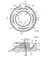
- an ostomy coupling 10 comprises a plastics bodyside coupling member 12 and a plastics bagside coupling member 14, which are securable together by means of a resilient split ring 16 carried by the bodyside member 12.
- a resilient split ring 16 carried by the bodyside member 12.
- the bodyside member 12 comprises an annular flange 18 surrounding an aperture 20, and secured to an adhesive pad or wafer 22. Any suitable skin adhesive may be used, and such adhesives are well known to the skilled man.
- the outer wall 24 is formed with a radially outwardly facing annular clearance or partial recess 30 (best seen in Fig. 2) which communicates with the channel 28 through a plurality of spaced apart slots 32 through the outer wall 24.
- the split ring 16 is received within the annular recess 30.
- the split ring 16 comprises a handle region 34 from which extend two arcuate limbs 36.
- the limbs 36 each consist generally of a radially inwardly facing planar portion 38 from which depends a radially outwardly facing skirt portion 40.
- the skirt portion 40 is inclined, or tapered, to provide a generally smooth shape which blends in to the shape of the bodyside member 12, and generally provides a smooth, gradual, profile transition between the upstanding outer wall 24 and the peripheral region of the flange 18.
- the overall profile of the bodyside coupling member 12 carrying the split ring 16 is generally trapezoid.
- Such a smooth shape is advantageous in making the coupling less obtrusive through the wearer's clothing, and in reducing any risk of the coupling catching on clothing.
- a number of locking tabs 42 Projecting from the radially inner edge of the split ring 16 are a number of locking tabs 42 which, when the ring 16 is in a central position on the bodyside member 12 (illustrated in Fig. 3), project through the slots 32 into the channel 28 for locking the coupling members together (as described further below).
- the circumferential ends 44 of the tabs 42 are tapered, or rounded, and the corresponding edges of each slot are also rounded or tapered with a generally complementary profile.
- the tapered ends 44 of the tabs 42 slide against the confronting edges of the slots with a camming action, to withdraw, or retract, the tabs 42 at least partly from the channel 28.
- each tab 42 (as viewed in Fig. 1) is rounded or tapered to provide a snap-together function of the coupling (as described further below).
- the lower edge 48 has a more square locking profile for locking the bagside coupling member 14 within the channel 28 until the split ring 16 is deformed to withdraw the tabs 42 in the manner described above.
- the surface 50 of the inner wall 26 which faces the outer wall 24 curves towards the outer wall 24 such that the channel 28 narrows in width towards the channel floor 52.
- the surface 50 acts as a curved (tapered) seal seat for the seal of the bagside coupling member 14 when the two members are fastened together.
- the channel is wider than it is deep.
- the bagside coupling member 14 comprises a generally annular flange 60 secured (for example, welded) to a wall 62 of an ostomy pouch, to surround its entry aperture.
- a generally cylindrical rib 64 Projecting from the flange 60 is a generally cylindrical rib 64 dimensioned to fit within the channel 28 of the bodyside member 12.
- the rib 64 has an annular undercut projection 66 on its radially outer edge, for co-operating with the locking tabs 42 of the split ring 16.
- the projection 66 has a rounded or tapered leading edge 68, and a more square rear locking surface 70.
- the rib 64 On its radially inner face, the rib 64 carries an integrally moulded deflectable seal wing 72 for bearing against the seat surface 50 of the bodyside member 12.
- the deflectable seal 72 has a generally curved shape, and tapers in thickness towards its free end. In its natural condition, the seal 72 is generally less curved than the seat surface 50, such that the seal 72 is somewhat "oversize” and has to deflect at least to some degree when entering the channel 28.
- the deflectable seal 72 is deflected to bear against the more curved seal seat surface 50 of the inner wall 26.
- the seal 72 is deflected to form a contact region in the form of an annular band (i.e. extending over a range of axial positions), rather than a so-called annular point seal.
- annular band i.e. extending over a range of axial positions
- a curved sealing seat and a curved deflectable seal
- a relatively long deflectable seal to be used within a reduced profile height (compared to an axial seal seat).
- This can enable the excellent performance of the axial seal seat to be used in a reduced height coupling profile.
- it is possible to reduce the profile height of the bodyside coupling to about 4.5 mm (or even less), which might in some circumstances be difficult to achieve using a purely axial seal.
- a second embodiment of ostomy coupling is now described. This is similar in many respects to the first embodiment, and where appropriate the same reference numerals are used to denote the same features as those of the first embodiment.
- the bagside coupling member 14 is identical to that of the first embodiment. Also, the bodyside coupling member 12 employs the same curved seal seat 50, to enable a relative large sealing surface to be accommodated within a relatively low profile height, without reducing the seal performance.
- the main difference in the second embodiment lies in the design of the split ring 16, and the manner in which it is mounted on the bodyside coupling member 12.
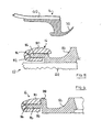
- the split ring 16 is bifurcated to have an approximately U-shaped cross section, including upper and lower portions 80 and 82, respectively above and below an annular clearance 84.
- the split ring 16 is carried on a radially projecting flange 86 of the bodyside coupling member 12. The flange 86 is received within the clearance 84 of the split ring 16, and the upper and lower portions 80 and 82 hold the split ring 16 captive on the flange 86.
- the outer cylindrical wall 24 is replaced by a plurality of wall segments 88 spaced apart by spaces 90 equivalent to the slots 32 of the first embodiment.
- the upper portion 80 of the split ring 16 carries locking tabs 92 equivalent to the locking tabs 42 of the first embodiment.
- the tabs 92 project through the spaces 90 to engage the bagside coupling member 14 in the same manner as the first embodiment.
- the circumferential ends of the tabs 92, and the corresponding end surfaces of the wall segments 88, are tapered or rounded to cause the tabs 92 to be withdrawn when a force is applied to the handle 34 of the split ring 16 tending to rotate the split ring 16.
- the upper edges of the tabs 92 are also rounded or tapered to provide a snap-fit with the bagside coupling member 14. The split ring 16 thus functions in the same manner as in the first embodiment.
- the height of the wall segments 88 can be less than the height of the outer wall 24 of the first embodiment. It is preferred that the wall segments 88 are only about as high as the upper region 82 of the split ring 16, so that the wall segments 88 are generally flush with the upper surface of the split ring 16. Typically, with such a design, it is possible to reduce the profile height of the bodyside coupling member to about 3.8 - 3.9 mm (or even less), which may be even lower than the first embodiment.
Landscapes
- Health & Medical Sciences (AREA)
- Heart & Thoracic Surgery (AREA)
- Life Sciences & Earth Sciences (AREA)
- Orthopedic Medicine & Surgery (AREA)
- Engineering & Computer Science (AREA)
- Biomedical Technology (AREA)
- Epidemiology (AREA)
- Vascular Medicine (AREA)
- Nursing (AREA)
- Animal Behavior & Ethology (AREA)
- General Health & Medical Sciences (AREA)
- Public Health (AREA)
- Veterinary Medicine (AREA)
- Orthopedics, Nursing, And Contraception (AREA)
- Materials For Medical Uses (AREA)
Claims (19)
- Accouplement de stomie pouvant être fixé par un élément de verrouillage déformable, l'accouplement comprenant :un premier élément d'accouplement (14) comprenant une ailette d'étanchéité pouvant s'incurver (72) s'étendant autour d'une ouverture d'accouplement du premier élément d'accouplement,un second élément d'accouplement (12) comprenant une surface de base d'élément d'étanchéité (50) s'étendant autour d'une ouverture d'accouplement du second élément d'accouplement, la surface de base d'élément d'étanchéité étant effilée avec une inclinaison incurvée dans une direction allant vers le premier élément d'accouplement lorsque les éléments d'accouplement se trouvent dans un état assemblé, etun élément de verrouillage déformable (16) sous la forme d'un anneau fendu, ou se comportant sensiblement comme celui-ci, et étant supporté sur un des éléments d'accouplement pour fixer de façon amovible les éléments d'accouplement ensemble,caractérisé en ce que :la surface de base d'élément d'étanchéité (50) est une surface concave orientée vers l'extérieur,la forme naturelle de l'ailette d'étanchéité pouvant s'incurver est moins incurvée que la surface de base d'élément d'étanchéité et, en utilisation, lorsque les éléments d'accouplement se trouvent dans ledit état assemblé, l'ailette d'étanchéité pouvant s'incurver est déformée pour adopter une courbure afin de reposer contre l'inclinaison incurvée de la surface de base d'élément d'étanchéité.
- Accouplement de stomie selon la revendication 1, dans lequel la surface de base d'élément d'étanchéité (50) s'incurve d'environ 90 degrés.
- Accouplement de stomie selon la revendication 2, dans lequel la surface de base d'élément d'étanchéité (50) s'incurve depuis une première direction généralement parallèle au plan du second élément d'accouplement vers une seconde direction généralement perpendiculaire audit plan.
- Accouplement de stomie selon la revendication 1, 2 ou 3, dans lequel la surface de base d'élément d'étanchéité (50) s'incurve généralement uniformément sur une partie principale de la surface de base d'élément d'étanchéité.
- Accouplement de stomie selon l'une quelconque des revendications précédentes, dans lequel l'élément de verrouillage déformable (16) est supporté par le second élément d'accouplement (12).
- Accouplement de stomie selon l'une quelconque .des revendications précédentes, dans lequel l'élément de verrouillage déformable (12) comprend une pluralité de protubérances de verrouillage (42 ; 92), et l'élément de verrouillage peut être dilaté pour déplacer les protubérances de verrouillage vers l'extérieur par une rotation de l'élément de verrouillage.
- Accouplement de stomie selon l'une quelconque des revendications précédentes, dans lequel l'ailette d'étanchéité pouvant s'incurver (72) présente une forme naturelle dans laquelle elle est incurvée dans la même direction que la surface de base d'élément d'étanchéité (50), l'ailette d'étanchéité pouvant s'incurver présentant une courbure inférieure à celle de la surface de base d'élément d'étanchéité, grâce à quoi lorsque l'ailette d'étanchéité pouvant s'incurver repose contre la surface de base d'élément d'étanchéité lorsque les éléments d'accouplement sont assemblés ensemble, l'ailette d'étanchéité est déformée pour présenter une forme plus incurvée.
- Accouplement de stomie (12) selon la revendication 5 ou une revendication quelconque dépendant de celle-ci, le second élément d'accouplement comprenant en outre :un guide (30 ; 86) pour l'élément de verrouillage, l'élément de verrouillage déformable (16) étant supporté de façon mobile par ledit guide,et dans lequel la surface de base d'élément d'étanchéité (50) s'étend autour d'une ouverture du second élément d'accouplement, la surface de base d'élément d'étanchéité étant effilée avec une inclinaison incurvée dans une direction globalement perpendiculaire au plan de l'élément de verrouillage et comprenant une surface concave orientée vers l'extérieur en direction de l'élément de verrouillage déformable (16), un dégagement radial existant entre la surface de base d'élément d'étanchéité (50) et l'un du guide (30 ; 86) et de l'élément de verrouillage (16) pour recevoir une partie dudit premier élément d'accouplement.
- Accouplement de stomie selon la revendication 8, dans lequel le second élément d'accouplement comprend en outre une première paroi (26) et une seconde paroi (24) définissant au moins une partie de canal (28) pour recevoir au moins une partie d'une nervure du premier élément d'accouplement, la première paroi (26) définissant ladite base d'élément d'étanchéité (50) et la base d'élément d'étanchéité étant effilée suivant une inclinaison incurvée en direction de la seconde paroi (24) de telle sorte que la largeur de la partie de canal (28) rétrécit avec une inclinaison incurvée vers le fond du canal.
- Accouplement de stomie selon la revendication 9, dans lequel la partie de canal (28) est plus large au moins à un point qu'elle n'est profonde.
- Accouplement de stomie selon la revendication 9 ou 10, dans lequel la partie de canal (28) est globalement continue.
- Accouplement de stomie selon la revendication 9 ou 10, comprenant une pluralité de parties de canal espacées définissant des segments de canal espacés.
- Accouplement de stomie selon la revendication 8, dans lequel le second élément d'accouplement comprend en outre :une bride à ouverture (18) depuis laquelle se dresse une paroi annulaire (24) comportant des surfaces radialement intérieure et extérieure, la surface radialement extérieure étant dotée d'un dégagement annulaire (30) pour définir ledit guide,où la bride (18) s'étend radialement vers l'extérieur de la paroi annulaire (24) et l'élément de verrouillage déformable comporte une face extérieure inclinée (40) pour former une forme de profil généralement incliné entre la bride (18) et la paroi annulaire (24).
- Accouplement de stomie selon la revendication 13, dans lequel l'élément de verrouillage déformable (16) présente une forme de profil généralement lisse entre la bride (18) et la paroi annulaire (24).
- Accouplement de stomie selon la revendication 13 ou 14, dans lequel le profil du second élément d'accouplement (12) associé à l'élément de verrouillage déformable (16) supporté sur celui-ci est généralement trapézoïdal.
- Accouplement de stomie selon la revendication 13, 14 ou 15, dans lequel le second élément d'accouplement comprend en outre un canal annulaire (28) destiné à recevoir le premier élément d'accouplement, le canal annulaire communiquant avec le dégagement annulaire (30) par l'intermédiaire d'une pluralité d'ouvertures (32).
- Accouplement de stomie selon la revendication 8, dans lequel :ledit guide est un guide dépassant globalement radialement (86), etl'élément de verrouillage déformable (16) comprend des première et seconde branches, chaque branche comprenant des parties supérieure et inférieure respectives (80, 82) avec un dégagement (84) entre celles-ci, le guide (86) étant reçu à l'intérieur du dégagement et les parties supérieure et inférieure s'adaptant au-dessus et en dessous du guide pour maintenir l'élément de verrouillage sur celui-ci.
- Accouplement de stomie selon la revendication 17, dans lequel chaque branche de l'anneau fendu crée une bifurcation.
- Accouplement de stomie selon la revendication 17 ou 18, dans lequel l'anneau de verrouillage déformable comprend une pluralité de protubérances de verrouillage (92) et dans lequel l'élément d'accouplement comprend en outre une pluralité de segments de paroi (88), les protubérances de verrouillage (92) dépassant au travers d'espaces (90) entre des segments de paroi adjacents (88).
Applications Claiming Priority (2)
| Application Number | Priority Date | Filing Date | Title |
|---|---|---|---|
| GBGB9929517.2A GB9929517D0 (en) | 1999-12-13 | 1999-12-13 | Ostomy coupling |
| GB9929517 | 1999-12-13 |
Publications (2)
| Publication Number | Publication Date |
|---|---|
| EP1108404A1 EP1108404A1 (fr) | 2001-06-20 |
| EP1108404B1 true EP1108404B1 (fr) | 2007-10-03 |
Family
ID=10866278
Family Applications (1)
| Application Number | Title | Priority Date | Filing Date |
|---|---|---|---|
| EP00126772A Expired - Lifetime EP1108404B1 (fr) | 1999-12-13 | 2000-12-06 | Accouplement d'ostomie |
Country Status (9)
| Country | Link |
|---|---|
| US (1) | US6802831B2 (fr) |
| EP (1) | EP1108404B1 (fr) |
| AT (1) | ATE374586T1 (fr) |
| AU (1) | AU777946B2 (fr) |
| CA (1) | CA2328392C (fr) |
| DE (1) | DE60036597T2 (fr) |
| DK (1) | DK1108404T3 (fr) |
| ES (1) | ES2292400T3 (fr) |
| GB (1) | GB9929517D0 (fr) |
Families Citing this family (14)
| Publication number | Priority date | Publication date | Assignee | Title |
|---|---|---|---|---|
| DK173488B1 (da) * | 2000-01-07 | 2000-12-18 | Biotap As | Stomipose med kobling |
| DK176243B1 (da) | 2003-10-24 | 2007-04-16 | Coloplast As | En stomipåsætningsplade og en fremgangsmåde til frembringelse heraf |
| EP1959881B1 (fr) * | 2005-11-24 | 2012-02-29 | Coloplast A/S | Assemblage de raccordement pour ostomie |
| US8142406B2 (en) * | 2005-12-07 | 2012-03-27 | Convatec Technologies Inc. | Ostomy coupling |
| FR2913593B1 (fr) * | 2007-03-15 | 2010-01-08 | Braun Medical Sas | Raccord pour appareillage de stomie,et appareillage de stomie le comportant |
| GB2458477B (en) * | 2008-03-19 | 2011-11-23 | Stanley Barcroft | One-piece colostomy pouch with handle |
| US9545329B2 (en) | 2011-02-21 | 2017-01-17 | International Medical Technology | Flow control and collection device |
| US9498371B2 (en) | 2011-02-21 | 2016-11-22 | International Medical Technology, Inc. | Flow control and collection device |
| GB201402289D0 (en) * | 2014-02-11 | 2014-03-26 | T G Eakin Ltd | Seal for use with a stoma |
| USD862691S1 (en) | 2016-05-12 | 2019-10-08 | Marlen Manufacturing And Development Co. | Ostomy pouch |
| EP3454797B1 (fr) | 2016-05-12 | 2022-02-09 | Marlen Manufacturing And Development Co. | Ensembles de montage pour appareils de stomie comprenant un élément adhésif barrière cutanée ayant un périmètre extérieur à plusieurs pétales |
| US10945873B2 (en) | 2016-05-12 | 2021-03-16 | Marlen Manufacturing And Development Co. | Multi-petaled mounting members for ostomy pouches |
| WO2020055998A1 (fr) * | 2018-09-12 | 2020-03-19 | Hollister Incorporated | Barrière de stomie convexe et procédé de formation de barrières de stomie convexes de souplesse différente |
| EP4271332A4 (fr) * | 2020-12-31 | 2024-11-27 | ConvaTec Technologies Inc. | Système d'accouplement pour des appareils de stomie |
Family Cites Families (6)
| Publication number | Priority date | Publication date | Assignee | Title |
|---|---|---|---|---|
| NZ186585A (en) * | 1977-03-30 | 1981-03-16 | Kingsdown Medical Consultants | Coupling for joining pad or dressing to an ostomy bag |
| US4850985A (en) * | 1988-08-01 | 1989-07-25 | E. R. Squibb & Sons, Inc. | Ostomy system utilizing a split ring to engage a two element coupling assembly |
| DK170206B1 (da) * | 1993-02-22 | 1995-06-19 | Coloplast As | Stomikobling |
| GB2298794A (en) * | 1995-03-09 | 1996-09-18 | Squibb & Sons Inc | Ostomy coupling with intervening support ring |
| GB2301533B (en) * | 1995-04-13 | 1999-05-05 | Squibb & Sons Inc | Ostomy coupling |
| GB9507666D0 (en) * | 1995-04-13 | 1995-05-31 | Squibb & Sons Inc | Ostomy coupling |
-
1999
- 1999-12-13 GB GBGB9929517.2A patent/GB9929517D0/en not_active Ceased
-
2000
- 2000-12-06 AT AT00126772T patent/ATE374586T1/de not_active IP Right Cessation
- 2000-12-06 ES ES00126772T patent/ES2292400T3/es not_active Expired - Lifetime
- 2000-12-06 DE DE60036597T patent/DE60036597T2/de not_active Expired - Lifetime
- 2000-12-06 EP EP00126772A patent/EP1108404B1/fr not_active Expired - Lifetime
- 2000-12-06 DK DK00126772T patent/DK1108404T3/da active
- 2000-12-12 US US09/735,206 patent/US6802831B2/en not_active Expired - Lifetime
- 2000-12-12 AU AU72186/00A patent/AU777946B2/en not_active Ceased
- 2000-12-13 CA CA2328392A patent/CA2328392C/fr not_active Expired - Fee Related
Also Published As
| Publication number | Publication date |
|---|---|
| GB9929517D0 (en) | 2000-02-09 |
| DE60036597T2 (de) | 2008-06-26 |
| US20010004687A1 (en) | 2001-06-21 |
| EP1108404A1 (fr) | 2001-06-20 |
| AU7218600A (en) | 2001-06-14 |
| CA2328392A1 (fr) | 2001-06-13 |
| US6802831B2 (en) | 2004-10-12 |
| DK1108404T3 (da) | 2008-02-04 |
| DE60036597D1 (de) | 2007-11-15 |
| AU777946B2 (en) | 2004-11-04 |
| CA2328392C (fr) | 2010-02-23 |
| ATE374586T1 (de) | 2007-10-15 |
| ES2292400T3 (es) | 2008-03-16 |
Similar Documents
| Publication | Publication Date | Title |
|---|---|---|
| CA2328392C (fr) | Raccord pour stomie | |
| US5501677A (en) | Two-piece ostomy appliance and low-profile coupling ring assembly | |
| AU2006249243B2 (en) | Ostomy coupling | |
| EP1407731B1 (fr) | Accouplement d'ostomie | |
| EP0865779A1 (fr) | Accouplement d'orifice, pièces correspondantes et méthode de production | |
| EP0689810B1 (fr) | Dispositif d'ostomie en deux parties avec anneau de pression monté sur la poche | |
| CA2052598C (fr) | Dispositif d'insertion pour appareil d'ostomie | |
| AU762628B2 (en) | Ostomy coupling | |
| CA1288652C (fr) | Appareil d'ostomie, et sa bague d'accouplement | |
| EP0964662B1 (fr) | Systeme de piece d'insertion convexe pour accessoire de stomie | |
| JPH0626554B2 (ja) | 人工肛門用具 | |
| JP2777182B2 (ja) | 人工肛門用カップリング | |
| CA2227343A1 (fr) | Raccord pour orifice | |
| AU2037799A (en) | Coupling for ostomy appliance, and ostomy appliance comprising such a coupling | |
| EP0347068B1 (fr) | Accouplement pour une poche d'ostomie | |
| EP0680736B1 (fr) | Accouplement d'ostomie |
Legal Events
| Date | Code | Title | Description |
|---|---|---|---|
| PUAI | Public reference made under article 153(3) epc to a published international application that has entered the european phase |
Free format text: ORIGINAL CODE: 0009012 |
|
| AK | Designated contracting states |
Kind code of ref document: A1 Designated state(s): AT BE CH CY DE DK ES FI FR GB GR IE IT LI LU MC NL PT SE TR |
|
| AX | Request for extension of the european patent |
Free format text: AL;LT;LV;MK;RO;SI |
|
| 17P | Request for examination filed |
Effective date: 20011217 |
|
| AKX | Designation fees paid |
Free format text: AT BE CH CY DE DK ES FI FR GB GR IE IT LI LU MC NL PT SE TR |
|
| GRAP | Despatch of communication of intention to grant a patent |
Free format text: ORIGINAL CODE: EPIDOSNIGR1 |
|
| GRAS | Grant fee paid |
Free format text: ORIGINAL CODE: EPIDOSNIGR3 |
|
| GRAA | (expected) grant |
Free format text: ORIGINAL CODE: 0009210 |
|
| AK | Designated contracting states |
Kind code of ref document: B1 Designated state(s): AT BE CH CY DE DK ES FI FR GB GR IE IT LI LU MC NL PT SE TR |
|
| REG | Reference to a national code |
Ref country code: GB Ref legal event code: FG4D |
|
| REG | Reference to a national code |
Ref country code: CH Ref legal event code: EP |
|
| REG | Reference to a national code |
Ref country code: IE Ref legal event code: FG4D |
|
| REF | Corresponds to: |
Ref document number: 60036597 Country of ref document: DE Date of ref document: 20071115 Kind code of ref document: P |
|
| REG | Reference to a national code |
Ref country code: SE Ref legal event code: TRGR |
|
| ET | Fr: translation filed | ||
| REG | Reference to a national code |
Ref country code: DK Ref legal event code: T3 |
|
| REG | Reference to a national code |
Ref country code: ES Ref legal event code: FG2A Ref document number: 2292400 Country of ref document: ES Kind code of ref document: T3 |
|
| NLV1 | Nl: lapsed or annulled due to failure to fulfill the requirements of art. 29p and 29m of the patents act | ||
| REG | Reference to a national code |
Ref country code: CH Ref legal event code: PL |
|
| PG25 | Lapsed in a contracting state [announced via postgrant information from national office to epo] |
Ref country code: CH Free format text: LAPSE BECAUSE OF FAILURE TO SUBMIT A TRANSLATION OF THE DESCRIPTION OR TO PAY THE FEE WITHIN THE PRESCRIBED TIME-LIMIT Effective date: 20071003 Ref country code: NL Free format text: LAPSE BECAUSE OF FAILURE TO SUBMIT A TRANSLATION OF THE DESCRIPTION OR TO PAY THE FEE WITHIN THE PRESCRIBED TIME-LIMIT Effective date: 20071003 Ref country code: LI Free format text: LAPSE BECAUSE OF FAILURE TO SUBMIT A TRANSLATION OF THE DESCRIPTION OR TO PAY THE FEE WITHIN THE PRESCRIBED TIME-LIMIT Effective date: 20071003 |
|
| PG25 | Lapsed in a contracting state [announced via postgrant information from national office to epo] |
Ref country code: PT Free format text: LAPSE BECAUSE OF FAILURE TO SUBMIT A TRANSLATION OF THE DESCRIPTION OR TO PAY THE FEE WITHIN THE PRESCRIBED TIME-LIMIT Effective date: 20080303 |
|
| PG25 | Lapsed in a contracting state [announced via postgrant information from national office to epo] |
Ref country code: AT Free format text: LAPSE BECAUSE OF FAILURE TO SUBMIT A TRANSLATION OF THE DESCRIPTION OR TO PAY THE FEE WITHIN THE PRESCRIBED TIME-LIMIT Effective date: 20071003 |
|
| PG25 | Lapsed in a contracting state [announced via postgrant information from national office to epo] |
Ref country code: MC Free format text: LAPSE BECAUSE OF NON-PAYMENT OF DUE FEES Effective date: 20071231 |
|
| PLBE | No opposition filed within time limit |
Free format text: ORIGINAL CODE: 0009261 |
|
| STAA | Information on the status of an ep patent application or granted ep patent |
Free format text: STATUS: NO OPPOSITION FILED WITHIN TIME LIMIT |
|
| PG25 | Lapsed in a contracting state [announced via postgrant information from national office to epo] |
Ref country code: BE Free format text: LAPSE BECAUSE OF FAILURE TO SUBMIT A TRANSLATION OF THE DESCRIPTION OR TO PAY THE FEE WITHIN THE PRESCRIBED TIME-LIMIT Effective date: 20071003 |
|
| 26N | No opposition filed |
Effective date: 20080704 |
|
| PG25 | Lapsed in a contracting state [announced via postgrant information from national office to epo] |
Ref country code: IE Free format text: LAPSE BECAUSE OF NON-PAYMENT OF DUE FEES Effective date: 20071206 |
|
| REG | Reference to a national code |
Ref country code: GB Ref legal event code: 732E |
|
| PG25 | Lapsed in a contracting state [announced via postgrant information from national office to epo] |
Ref country code: GR Free format text: LAPSE BECAUSE OF FAILURE TO SUBMIT A TRANSLATION OF THE DESCRIPTION OR TO PAY THE FEE WITHIN THE PRESCRIBED TIME-LIMIT Effective date: 20080104 |
|
| PG25 | Lapsed in a contracting state [announced via postgrant information from national office to epo] |
Ref country code: FI Free format text: LAPSE BECAUSE OF FAILURE TO SUBMIT A TRANSLATION OF THE DESCRIPTION OR TO PAY THE FEE WITHIN THE PRESCRIBED TIME-LIMIT Effective date: 20071003 |
|
| PG25 | Lapsed in a contracting state [announced via postgrant information from national office to epo] |
Ref country code: CY Free format text: LAPSE BECAUSE OF FAILURE TO SUBMIT A TRANSLATION OF THE DESCRIPTION OR TO PAY THE FEE WITHIN THE PRESCRIBED TIME-LIMIT Effective date: 20071003 |
|
| PG25 | Lapsed in a contracting state [announced via postgrant information from national office to epo] |
Ref country code: LU Free format text: LAPSE BECAUSE OF NON-PAYMENT OF DUE FEES Effective date: 20071206 |
|
| PG25 | Lapsed in a contracting state [announced via postgrant information from national office to epo] |
Ref country code: TR Free format text: LAPSE BECAUSE OF FAILURE TO SUBMIT A TRANSLATION OF THE DESCRIPTION OR TO PAY THE FEE WITHIN THE PRESCRIBED TIME-LIMIT Effective date: 20071003 |
|
| REG | Reference to a national code |
Ref country code: FR Ref legal event code: TP |
|
| PGFP | Annual fee paid to national office [announced via postgrant information from national office to epo] |
Ref country code: DK Payment date: 20101210 Year of fee payment: 11 |
|
| PGFP | Annual fee paid to national office [announced via postgrant information from national office to epo] |
Ref country code: GB Payment date: 20101201 Year of fee payment: 11 Ref country code: IT Payment date: 20101218 Year of fee payment: 11 |
|
| PGFP | Annual fee paid to national office [announced via postgrant information from national office to epo] |
Ref country code: DE Payment date: 20101130 Year of fee payment: 11 |
|
| PGFP | Annual fee paid to national office [announced via postgrant information from national office to epo] |
Ref country code: FR Payment date: 20111219 Year of fee payment: 12 |
|
| PGFP | Annual fee paid to national office [announced via postgrant information from national office to epo] |
Ref country code: ES Payment date: 20120116 Year of fee payment: 12 |
|
| PG25 | Lapsed in a contracting state [announced via postgrant information from national office to epo] |
Ref country code: SE Free format text: LAPSE BECAUSE OF NON-PAYMENT OF DUE FEES Effective date: 20121207 |
|
| REG | Reference to a national code |
Ref country code: DK Ref legal event code: EBP |
|
| GBPC | Gb: european patent ceased through non-payment of renewal fee |
Effective date: 20121206 |
|
| REG | Reference to a national code |
Ref country code: FR Ref legal event code: ST Effective date: 20130830 |
|
| REG | Reference to a national code |
Ref country code: DE Ref legal event code: R119 Ref document number: 60036597 Country of ref document: DE Effective date: 20130702 |
|
| PG25 | Lapsed in a contracting state [announced via postgrant information from national office to epo] |
Ref country code: DE Free format text: LAPSE BECAUSE OF NON-PAYMENT OF DUE FEES Effective date: 20130702 |
|
| PG25 | Lapsed in a contracting state [announced via postgrant information from national office to epo] |
Ref country code: GB Free format text: LAPSE BECAUSE OF NON-PAYMENT OF DUE FEES Effective date: 20121206 Ref country code: FR Free format text: LAPSE BECAUSE OF NON-PAYMENT OF DUE FEES Effective date: 20130102 |
|
| PG25 | Lapsed in a contracting state [announced via postgrant information from national office to epo] |
Ref country code: IT Free format text: LAPSE BECAUSE OF NON-PAYMENT OF DUE FEES Effective date: 20121206 |
|
| PG25 | Lapsed in a contracting state [announced via postgrant information from national office to epo] |
Ref country code: DK Free format text: LAPSE BECAUSE OF NON-PAYMENT OF DUE FEES Effective date: 20130102 |
|
| REG | Reference to a national code |
Ref country code: ES Ref legal event code: FD2A Effective date: 20140519 |
|
| PG25 | Lapsed in a contracting state [announced via postgrant information from national office to epo] |
Ref country code: ES Free format text: LAPSE BECAUSE OF NON-PAYMENT OF DUE FEES Effective date: 20121207 |
|
| PGFP | Annual fee paid to national office [announced via postgrant information from national office to epo] |
Ref country code: SE Payment date: 20170213 Year of fee payment: 17 |