EP1108452B1 - Dispositif de liasion entre une fixation de chaussure et une planche de glisse - Google Patents
Dispositif de liasion entre une fixation de chaussure et une planche de glisse Download PDFInfo
- Publication number
- EP1108452B1 EP1108452B1 EP00811152A EP00811152A EP1108452B1 EP 1108452 B1 EP1108452 B1 EP 1108452B1 EP 00811152 A EP00811152 A EP 00811152A EP 00811152 A EP00811152 A EP 00811152A EP 1108452 B1 EP1108452 B1 EP 1108452B1
- Authority
- EP
- European Patent Office
- Prior art keywords
- ring
- disk
- snowboard
- board
- relative
- Prior art date
- Legal status (The legal status is an assumption and is not a legal conclusion. Google has not performed a legal analysis and makes no representation as to the accuracy of the status listed.)
- Expired - Lifetime
Links
- 230000027455 binding Effects 0.000 claims abstract description 21
- 238000009739 binding Methods 0.000 claims abstract description 21
- 230000013011 mating Effects 0.000 claims 1
- 238000010276 construction Methods 0.000 description 3
- 229920003023 plastic Polymers 0.000 description 3
- 239000004033 plastic Substances 0.000 description 3
- 238000006073 displacement reaction Methods 0.000 description 2
- 230000003100 immobilizing effect Effects 0.000 description 1
- 238000003780 insertion Methods 0.000 description 1
- 230000037431 insertion Effects 0.000 description 1
- 239000000463 material Substances 0.000 description 1
- 239000002184 metal Substances 0.000 description 1
- JTJMJGYZQZDUJJ-UHFFFAOYSA-N phencyclidine Chemical compound C1CCCCN1C1(C=2C=CC=CC=2)CCCCC1 JTJMJGYZQZDUJJ-UHFFFAOYSA-N 0.000 description 1
- 238000000926 separation method Methods 0.000 description 1
Images

Classifications
-
- A—HUMAN NECESSITIES
- A63—SPORTS; GAMES; AMUSEMENTS
- A63C—SKATES; SKIS; ROLLER SKATES; DESIGN OR LAYOUT OF COURTS, RINKS OR THE LIKE
- A63C10/00—Snowboard bindings
- A63C10/16—Systems for adjusting the direction or position of the bindings
- A63C10/18—Systems for adjusting the direction or position of the bindings about a vertical rotation axis relative to the board
-
- A—HUMAN NECESSITIES
- A63—SPORTS; GAMES; AMUSEMENTS
- A63C—SKATES; SKIS; ROLLER SKATES; DESIGN OR LAYOUT OF COURTS, RINKS OR THE LIKE
- A63C10/00—Snowboard bindings
- A63C10/16—Systems for adjusting the direction or position of the bindings
- A63C10/20—Systems for adjusting the direction or position of the bindings in longitudinal or lateral direction relative to the board
-
- A—HUMAN NECESSITIES
- A63—SPORTS; GAMES; AMUSEMENTS
- A63C—SKATES; SKIS; ROLLER SKATES; DESIGN OR LAYOUT OF COURTS, RINKS OR THE LIKE
- A63C10/00—Snowboard bindings
- A63C10/24—Calf or heel supports, e.g. adjustable high back or heel loops
Definitions
- the present invention relates to a binding device between a shoe binding and a gliding board, in particular a surfboard, comprising means for adjusting the position of the binding relative to the gliding board both in translation and in rotation.
- the positions adopted for the practice of surfing are very variable depending on the disciplines practiced, the level or habits of the user.
- the feet may be more or less spaced from each other or more or less inclined relative to the longitudinal axis of the surf, the orientations of the feet being generally not parallel to each other.
- it is therefore important to be able to change the position of the bindings on the surf and the orientation of these bindings relative to the surf.
- FR 2 736 842 proposes for this purpose an interface intended to be mounted between the surf and the binding, this interface comprising two rails, profiled in the form of slides, inserted longitudinally in the surf along its longitudinal axis and two plates provided with a slide that can move in the rails and can be oriented angularly about a vertical axis, rapid clamping means for immobilizing the plates on the surf.
- Each plate has four threaded holes for attaching the base of the shoe attachment, these four holes replacing the inserts that are found in standard boards.
- Such an interface has the advantage of a quick adjustment, but it requires a special board whose rigidity is increased by the insertion of the rails, the latter modifying in all cases the dynamic characteristics of the board.
- Such an interface also has a significant weight. Despite this, such an interface does not offer the possibility of adjusting the position of the fasteners by a displacement in the direction transverse to the longitudinal axis of the board. However, such a setting said "front / rear" is increasingly requested by
- Patent FR 2 755 025 also discloses a connection device between a gliding board and a shoe binding, this connecting device comprising a plate intended to be fixed by means of screws in the standard inserts (4 x 4). a surfboard, this plate having grooves parallel to the longitudinal axis of the board and having a T-shaped profile in which are mounted gibs for fixing the base of the shoe binding, adjustable type fastening around the a central disk in the example described.
- This construction has the advantage of adapting to any standard board, that is to say any board provided with inserts according to the usual standard 4 x 4, but it also does not allow to make a setting "before /back".
- a connecting device allowing a "forward / backward” adjustment is described in the patent application JP 11-197287.
- the base of the binding is maintained by the stacking of a perforated disc, a plate provided with four oblong holes or notches and a rectangular plate holding the whole on the surfboard by four screws.
- the intermediate plate can move in only one direction relative to the disk, along a graduated scale, but its oblong holes, oriented perpendicularly to its direction of movement, allow its displacement relative to the upper plate, allowing a "forward” adjustment. back".
- This construction is equivalent to a simplified construction simply using a perforated disk and a holding plate.
- a ring fixed on a gliding board retains by its inner contour an intermediate piece which supports a fixing.
- This intermediate piece comprises respectively with the attachment and the ring two eccentric and superposed outer circular contact surfaces, which allows the translation and rotation adjustment of the binding relative to the gliding board.
- the object of the invention is to provide a connection device with a simple and compact multidirectional adjustment and ensuring a very secure hold of the boot binding in a plane parallel to the gliding board.
- the connecting device is characterized in that it consists of a circular disc intended to be fixed to the gliding board and coming to fit into a circular ring intended to maintain the attachment of the shoe, the inner circular contour of the ring in which the disc fits eccentrically relative to the outer contour of the ring.
- the ring ensures a mechanical continuity between the base of the binding and the disc. This continuity and the relatively low eccentricity make it virtually impossible to move the fastener even if the fastening screws are loosened.
- the disk and the ring can be advantageously made of plastic, which reduces the weight relative to a metal execution.
- the amplitude of adjustment in a direction transverse to the longitudinal axis of the board is amply sufficient for the needs.
- its amplitude can be increased if necessary using a disc having parallel oblong holes for the passage of the fastening screws to the board.
- Adjustment by the eccentric ring may be continuous, but in this case, one of the rotational interlockings between the disk and the ring or between the ring and the mounting base, will take place by simple friction. It is better to adopt a setting almost continuous by means of teeth, on the one hand, between the disk and the ring and, on the other hand, between the ring and the mounting base. Of course, one of the links could be provided by teeth and the other by friction.
- the fastener partially shown in FIG. 1 comprises a flat base 1 having two substantially vertical side walls 2 and 3 and connected at the rear by a hoop 4. On the side walls 2 and 3, inside them, is articulated, in a known manner, a rear support piece 5 of rounded shape. Between the walls 2 and 3 further extend two straps not shown, provided with loops, for maintaining the shoe in the binding, in known manner.
- the shoe binding is secured to a gliding board 6 by means of a connecting device consisting of a circular disc 7 and a ring 8.
- the disc 7 has four oblong holes 9 arranged in a square for fixing from disk 9 to plate 6, in this case a surfboard provided with threaded inserts also arranged in a square according to the usual 4 ⁇ 4 standard.
- the ring 8 is also circular and is engaged in a circular cutout 10 base 1.
- the ring 8 has on about the upper half of its thickness, a circular inner contour 11 eccentric relative to its outer contour and this eccentricity is such that the inner and outer contours have a point of tangency A ( Figure 2).
- the ring 8 On the remainder of its thickness the ring 8 has a cylindrical portion 12 concentric with the circle 11 but of smaller inside diameter, defining a cylindrical interlocking zone for a corresponding cylindrical portion 13 of the disc 7 ( Figure 3).
- the wall 12 defines a first flat surface 14 at about mid-height of the ring 8. Above this span 14 extends a second surface 15 in which is formed a toothing 16.
- the ring 8 further has a notch 18 to facilitate the separation of the disc 7 and the 8.
- the ring 8 has, in the lower half of its height, a portion 19 of a diameter smaller than the outer contour of the ring and forming a fitting portion in the corresponding diameter of the cutout.
- This last cut extends over about the lower half of the thickness of the base 1 by defining a toothed surface in which is engaged a toothing 20 of the ring 8 corresponding to the teeth of the base.
- the disk 7 has, on its lower face, a toothing 21 coming to engage in the toothing 16 of the ring 8.
- the oblong holes 9 of the disk 7 have a countersink 22 for supporting the heads of the screws for fixing the disk 7 to the gliding board.
- Two of the holes 9 visible in Figure 3 differ slightly from the holes 9 shown in Figure 2 in that they have two narrowing defining three discrete positions for the fixing screws.
- the toothing 20, in cooperation with the toothing of the board 6, makes it possible to orient the shoe binding relative to the longitudinal axis of the board, in known manner.
- the ring 8 makes it possible to move the attachment relative to the disk 7, that is to say to the plate 6, in almost all the directions, as this is illustrated by FIGS. 4 and 5.
- the ring 8 is placed in such a way that the fastener occupies its leftmost position relative to the disk 7, that is to say its most advanced position in the direction of the spatula.
- the adjustment range of the fasteners in the longitudinal direction of the board 6 is increased by the oblong holes 9.
- the materials used for shoe binding, the disc and the ring are generally plastics.
- the teeth 16 and 21 could be replaced by simple rough surfaces or by an auxiliary friction ring.
Landscapes
- Footwear And Its Accessory, Manufacturing Method And Apparatuses (AREA)
- Bolts, Nuts, And Washers (AREA)
- Sealing Devices (AREA)
Description
- La présente invention concerne un dispositif de liaison entre une fixation de chaussure et une planche de glisse, en particulier une planche de surf, comprenant des moyens de réglage de la position de la fixation relativement à la planche de glisse aussi bien en translation qu'en rotation.
- Comme ceci est exposé dans le brevet FR 2 736 842, les positions adoptées pour la pratique du surf sont très variables en fonction des disciplines pratiquées, du niveau ou des habitudes de l'utilisateur. Comme il est relevé dans ce document, les pieds peuvent être plus ou moins écartés l'un de l'autre ou plus ou moins inclinés par rapport à l'axe longitudinal du surf, les orientations des pieds étant généralement non parallèles entre elles. Pour plus de détails on se référera à ce document. Il est donc important de pouvoir modifier la position des fixations sur le surf et l'orientation de ces fixations relativement au surf.
- Le document FR 2 736 842 propose à cet effet une interface destinée à être montée entre le surf et la fixation, cette interface comprenant deux rails, profilés en forme de coulisses, insérés longitudinalement dans le surf selon son axe longitudinal et deux platines munies d'un coulisseau pouvant se déplacer dans les rails et pouvant être orienté angulairement autour d'un axe vertical, des moyens de serrage rapide permettant d'immobiliser les platines sur le surf. Chaque platine présente quatre trous filetés pour la fixation de l'embase de la fixation de chaussure, ces quatre trous remplaçant les inserts que l'on trouve dans les planches standards. Une telle interface présente l'avantage d'un réglage rapide, mais elle nécessite une planche spéciale dont la rigidité est augmentée par l'insertion des rails, ces derniers modifiant dans tous les cas les caractéristiques dynamiques de la planche. Une telle interface présente en outre un poids important. Malgré cela, une telle interface n'offre pas la possibilité de régler la position des fixations par un déplacement dans le sens transversal à l'axe longitudinal de la planche. Or, un tel réglage dit "avant/arrière" est de plus en plus demandé par les utilisateurs.
- Du brevet FR 2 755 025 on connaît également un dispositif de liaison entre une planche de glisse et une fixation de chaussure, ce dispositif de liaison comprenant une platine destinée à être fixée au moyen de vis dans les inserts standards (4 x 4) d'une planche de surf, cette platine présentant des rainures parallèles à l'axe longitudinal de la planche et présentant un profil en T dans lesquels sont montés des lardons pour la fixation de l'embase de la fixation de chaussure, fixation de type orientable autour d'un disque central dans l'exemple décrit. Cette construction présente l'avantage de s'adapter à toute planche standard, c'est-à-dire toute planche munie d'inserts selon le standard usuel 4 x 4, mais elle ne permet pas non plus d'effectuer un réglage "avant/arrière".
- Un dispositif de liaison permettant un réglage "avant/arrière" est décrit dans la demande de brevet JP 11-197287. L'embase de la fixation est maintenue par l'empilage d'un disque ajouré, d'une plaque munie de quatre trous oblongs ou d'encoches et d'une plaque rectangulaire maintenant l'ensemble sur la planche de surf par quatre vis. Pour le réglage de l'orientation de la fixation l'empilage est simplement desserré. La plaque intermédiaire peut se déplacer dans une direction seulement relativement au disque, le long d'une échelle graduée, mais ses trous oblongs, orientés perpendiculairement à sa direction de déplacement, autorisent son déplacement relativement à la plaque supérieure, permettant un réglage "avant/arrière". Cette construction est équivalente à une construction simplifiée utilisant simplement un disque ajouré et une plaque de maintien. Dans tous les cas, un espace important est nécessaire, dans le plan du disque, entre le bord intérieur du disque et la plaque qui le maintient, pour le réglage, et le disque n'est maintenu, parallèlement à son plan, que par les forces de frottement engendrées par le serrage des vis. Ces forces peuvent s'avérer insuffisantes à retenir la fixation en cas d'efforts brusques et relativement élevés exercés sur la liaison, comme ceci se produit lors de la pratique du surf. De plus, étant donné les efforts que le disque ajouré doit supporter, celui-ci ne peut guère être réalisé en matière plastique.
- Dans FR-A-2 669 237, une bague fixée sur une planche de glisse retient par son contour intérieur une pièce intermédiaire qui supporte une fixation. Cette pièce intermédiaire comporte respectivement avec la fixation et la bague deux surfaces de contact circulaires extérieures excentrées et superposées, ce qui permet le réglage en translation et rotation de la fixation par rapport à la planche de glisse.
- L'invention a pour but de réaliser un dispositif de liaison à réglage multidirectionnel simple et compact et assurant un maintien très sûr de la fixation de chaussure dans un plan parallèle à la planche de glisse.
- Le dispositif de liaison selon l'invention est caractérisé en ce qu'il est constitué d'un disque circulaire destiné à être fixé à la planche de glisse et venant s'emboîter dans une bague circulaire destinée à venir maintenir la fixation de chaussure, le contour circulaire intérieur de la bague dans lequel le disque s'emboîte étant excentré relativement au contour extérieur de la bague.
- La bague assure une continuité mécanique entre l'embase de la fixation et le disque. Cette continuité et l'excentricité relativement faible rendent pratiquement impossible un déplacement de la fixation même si les vis de fixation sont desserrées. Le disque et la bague peuvent être avantageusement exécutés en matière plastique, ce qui en réduit le poids relativement à une exécution en métal.
- L'amplitude de réglage dans une direction transversale à l'axe longitudinal de la planche est amplement suffisante pour les besoins. En ce qui concerne le réglage selon l'axe longitudinal de la planche, son amplitude peut être augmentée si nécessaire en utilisant un disque présentant des trous oblongs parallèles pour le passage des vis de fixation à la planche.
- Le réglage par la bague excentrique peut être continu, mais dans ce cas, l'une des solidarisations en rotation, entre le disque et la bague ou entre la bague et l'embase de fixation, aura lieu par simple frottement. Il est préférable d'adopter un réglage quasi continu au moyen de dentures, d'une part, entre le disque et la bague et, d'autre part, entre la bague et l'embase de fixation. Bien entendu, l'une des liaisons pourrait être assurée par des dentures et l'autre par frottement.
- Le dessin annexé représente, à titre d'exemple, un mode d'exécution de l'invention.
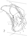
- La figure 1 est une vue en perspective d'une embase de fixation de surf montée sur une planche de surf au moyen d'un dispositif selon l'invention.
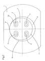
- La figure 2 est une vue partielle en plan, de dessus, de la fixation représentée à la figure 1.
- La figure 3 est un éclaté du disque et de la bague.
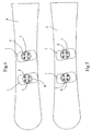
- La figure 4 illustre la possibilité de réglage avant/arrière sur une planche de surf.
- La figure 5 illustre la possibilité de réglage selon l'axe longitudinal de la planche de surf.
- La fixation représentée partiellement à la figure 1 comprend une embase plane 1 présentant deux parois latérales 2 et 3 sensiblement verticales et reliées à l'arrière par un arceau 4. Sur les parois latérales 2 et 3, à l'intérieur de celles-ci, est articulée, de manière connue, une pièce d'appui arrière 5 de forme arrondie. Entre les parois 2 et 3 s'étendent en outre deux sangles non représentées, munies de boucles, pour le maintien de la chaussure dans la fixation, de manière connue.
- La fixation de chaussure est rendue solidaire d'une planche de glisse 6 au moyen d'un dispositif de liaison constitué d'un disque circulaire 7 et d'une bague 8. Le disque 7 présente quatre trous oblongs 9 disposés en carré pour la fixation du disque 9 à la planche 6, en l'occurrence une planche de surf munie d'inserts filetés disposés également en carré selon le standard usuel 4 x 4. La bague 8 est également circulaire et elle est engagée dans une découpe circulaire 10 de l'embase 1.
- La bague 8 présente sur environ la moitié supérieure de son épaisseur, un contour intérieur circulaire 11 excentré relativement à son contour extérieur et cet excentrage est tel que les contours intérieur et extérieur présentent un point de tangence A (figure 2). Sur le reste de son épaisseur la bague 8 présente une partie cylindrique 12 concentrique au cercle 11 mais de diamètre intérieur plus petit, définissant une zone d'emboîtement cylindrique pour une partie cylindrique 13 correspondante du disque 7 (figure 3). La paroi 12 définit une première portée plane 14 à environ mi-hauteur de la bague 8. Au-dessus de cette portée 14 s'étend une seconde portée 15 dans laquelle est formée une denture de chant 16. Sur le dessin on distingue une zone exempte de dents 17 dont la raisons d'être est simplement l'amincissement de la bague dans cette zone. Sur le côté, la bague 8 présente en outre une encoche 18 pour faciliter la séparation du disque 7 et de la bague 8. A l'extérieur, la bague 8 présente, dans la moitié inférieure de sa hauteur, une partie 19 d'un diamètre plus petit que le contour extérieur de la bague et formant partie d'emboîtement dans la découpe de diamètre correspondant de l'embase 1. Cette dernière découpe s'étend sur environ la moitié inférieure de l'épaisseur de l'embase 1 en définissant une portée dentée dans laquelle vient s'engager une denture de chant 20 de la bague 8 correspondant à la denture de l'embase.
- Le disque 7 présente, sur sa face inférieure, une denture de chant 21 venant s'engager dans la denture 16 de la bague 8.
- Les trous oblongs 9 du disque 7 présentent un lamage 22 pour l'appui des têtes des vis de fixation du disque 7 à la planche de glisse. Deux des trous 9 visibles à la figure 3 diffèrent un peu des trous 9 représentés à la figure 2 en ce qu'il présentent deux rétrécissements définissant trois positions discrètes pour les vis de fixation.
- La denture 20, en coopération avec la denture de la planche 6, permet d'orienter la fixation de chaussure relativement à l'axe longitudinal de la planche, de manière connue.
- La bague 8 permet de déplacer la fixation relativement au disque 7, c'est-à-dire à la planche 6, dans pratiquement toutes les directions, comme ceci est illustrer par les figures 4 et 5.
- A la figure 4 les fixations sont orientées de telle sorte que le surfeur a les pieds dirigés vers le haut du dessin. La fixation de gauche occupe une position reculée au maximum relativement à une position médiane, tandis que la fixation de droite occupe une position avancée au maximum relativement à sa position médiane. Il est ainsi possible d'effectuer un réglage "avant/arrière".
- A la figure 5, fixation de gauche, la bague 8 est placée de telle sorte que la fixation occupe sa position la plus à gauche relativement au disque 7, c'est-à-dire sa position la plus avancée en direction de la spatule de la planche 6, tandis que la fixation de droite occupe sa position la plus à droite, c'est-à-dire la plus reculée en direction du talon de la planche. Il est ainsi possible de régler l'écartement des pieds. La plage de réglage des fixations dans la direction longitudinale de la planche 6 est augmentée par les trous oblongs 9.
- Les matériaux utilisés pour la fixation de chaussure, le disque et la bague sont généralement des plastiques.
- Les dentures 16 et 21 pourraient être remplacées par de simples surfaces rugueuses ou par une bague auxiliaire de friction.
Claims (4)
- Dispositif de liaison entre une fixation de chaussure et une planche de glisse comprenant des moyens de réglage de la position de la fixation relativement à la planche de glisse aussi bien en translation qu'en rotation, moyens de réglage comprenant un élément excentrique caractérisé en ce qu'il est constitué d'un disque circulaire (7) destiné à être fixé à la planche de glisse et venant s'emboîter dans une bague circulaire (8) destinée à venir maintenir la fixation de chaussure sur la planche de glisse, le contour circulaire intérieur (11) de la bague dans lequel le disque s'emboîte étant excentré relativement au contour extérieur de la bague.
- Dispositif selon la revendication 1, caractérisé en ce que le disque (7) présente des trous oblongs (9) parallèles pour sa fixation à la planche au moyen de vis.
- Dispositif selon la revendication 1 ou 2, caractérisé en ce que le disque (7) et l'intérieur de la bague (8) présentent des dentures (21, 16) de profils conjugués et coopérant ensemble pour la solidarisation du disque et de la bague en rotation.
- Dispositif selon l'une des revendications 1 à 3, caractérisé en ce que la bague (8) présente une denture (20) destinée à coopérer avec une denture de la fixation de chaussure pour le maintien de celle-ci en rotation.
Applications Claiming Priority (2)
| Application Number | Priority Date | Filing Date | Title |
|---|---|---|---|
| FR9915657 | 1999-12-13 | ||
| FR9915657A FR2802109B1 (fr) | 1999-12-13 | 1999-12-13 | Dispositif de liaison entre une fixation de chaussure et une planche de glisse |
Publications (2)
| Publication Number | Publication Date |
|---|---|
| EP1108452A1 EP1108452A1 (fr) | 2001-06-20 |
| EP1108452B1 true EP1108452B1 (fr) | 2006-03-15 |
Family
ID=9553157
Family Applications (1)
| Application Number | Title | Priority Date | Filing Date |
|---|---|---|---|
| EP00811152A Expired - Lifetime EP1108452B1 (fr) | 1999-12-13 | 2000-12-06 | Dispositif de liasion entre une fixation de chaussure et une planche de glisse |
Country Status (5)
| Country | Link |
|---|---|
| US (1) | US6783146B1 (fr) |
| EP (1) | EP1108452B1 (fr) |
| AT (1) | ATE320290T1 (fr) |
| DE (1) | DE60026685T2 (fr) |
| FR (1) | FR2802109B1 (fr) |
Families Citing this family (11)
| Publication number | Priority date | Publication date | Assignee | Title |
|---|---|---|---|---|
| FR2817162B1 (fr) * | 2000-11-24 | 2003-06-13 | Salomon Sa | Embase de support d'une chaussure sur une planche, l'embase etant munie d'un dispositif de positionnement sur la planche |
| FR2834909B1 (fr) * | 2002-01-18 | 2004-04-09 | Emery Sa | Perfectionnement pour dispositif de retenue d'une chaussure sur une planche de glisse sur neige du type surf |
| DE10335850A1 (de) * | 2003-08-06 | 2005-07-07 | Head Sport Ag | Snowboard-Bindung |
| WO2008008261A2 (fr) * | 2006-07-07 | 2008-01-17 | The Burton Corporation | Assise plantaire pour fixation de planche de glisse |
| CN101420832B (zh) * | 2007-10-23 | 2012-03-28 | 鸿富锦精密工业(深圳)有限公司 | 旋转定位结构及电子装置 |
| US8132818B2 (en) * | 2008-12-03 | 2012-03-13 | The Burton Corporation | Binding components for a gliding board |
| US8662505B2 (en) * | 2008-12-03 | 2014-03-04 | The Burton Corporation | Binding components for a gliding board |
| US8167321B2 (en) * | 2008-12-03 | 2012-05-01 | The Burton Corporation | Binding components for a gliding board |
| US9254434B2 (en) | 2014-06-23 | 2016-02-09 | Tzy Shenq Enterprise Co., Ltd. | Fixation seat for ski shoe |
| US9114309B1 (en) * | 2014-06-23 | 2015-08-25 | Tzy Shenq Enterprise Co., Ltd. | Fixation seat for ski shoe |
| JP6153685B1 (ja) * | 2017-04-11 | 2017-06-28 | 株式会社 Jp Tight | スノーボードビンディング用プレート |
Family Cites Families (10)
| Publication number | Priority date | Publication date | Assignee | Title |
|---|---|---|---|---|
| US5890730A (en) * | 1994-08-18 | 1999-04-06 | Switch Manufacturing | Snowboard boot and binding apparatus |
| FR2669237B1 (fr) * | 1990-11-21 | 1993-05-07 | Finiel Remi | Fixations de securite reglables coupees pour surf des neiges. |
| DE9108513U1 (de) * | 1991-07-10 | 1991-09-26 | F 2 International Ges.m.b.H., Kirchdorf | Bindung für Snowboards |
| US5957479A (en) * | 1995-03-02 | 1999-09-28 | Items International, Inc. | Snowboard binding assembly |
| FR2736842B1 (fr) | 1995-07-21 | 1997-09-26 | Salomon Sa | Planche de glisse adaptee a la pratique du surf sur neige. |
| IT1288636B1 (it) * | 1996-07-05 | 1998-09-23 | Nordica Spa | Dispositivo di regolazione angolare particolarmente per un attacco da snowboard |
| FR2755025A1 (fr) | 1996-10-24 | 1998-04-30 | Fin S International | Dispositif de liaison entre une planche a usage sportif, notamment une planche a neige, et une fixation de chaussure |
| US5941552A (en) * | 1996-12-20 | 1999-08-24 | Bc Creations, Inc. | Adjustable snowboard binding apparatus and method |
| US5967542A (en) * | 1997-11-25 | 1999-10-19 | Sims Sports, Inc. | Mounting disk and base for snowboard binding |
| JPH11197287A (ja) | 1998-01-08 | 1999-07-27 | Car Mate Mfg Co Ltd | スノーボードバインディング取付装置 |
-
1999
- 1999-12-13 FR FR9915657A patent/FR2802109B1/fr not_active Expired - Fee Related
-
2000
- 2000-11-27 US US09/722,046 patent/US6783146B1/en not_active Expired - Fee Related
- 2000-12-06 DE DE60026685T patent/DE60026685T2/de not_active Expired - Lifetime
- 2000-12-06 AT AT00811152T patent/ATE320290T1/de not_active IP Right Cessation
- 2000-12-06 EP EP00811152A patent/EP1108452B1/fr not_active Expired - Lifetime
Also Published As
| Publication number | Publication date |
|---|---|
| DE60026685D1 (de) | 2006-05-11 |
| DE60026685T2 (de) | 2006-09-21 |
| US6783146B1 (en) | 2004-08-31 |
| FR2802109A1 (fr) | 2001-06-15 |
| EP1108452A1 (fr) | 2001-06-20 |
| FR2802109B1 (fr) | 2002-01-25 |
| ATE320290T1 (de) | 2006-04-15 |
Similar Documents
| Publication | Publication Date | Title |
|---|---|---|
| EP0840640B1 (fr) | Dispositif de reglage de la position d'une fixation sur une planche de glisse | |
| EP1859843B1 (fr) | Ensemble comprenant une planche de glisse et un dispositif de retenue d'un article chaussant sur la planche | |
| EP1563876B1 (fr) | Ski de fond | |
| EP1103290B1 (fr) | Fixation de surf | |
| FR2776111A1 (fr) | Appui d'epaule reglable pour violons ou instruments analogues | |
| EP0838248B1 (fr) | Dispositif de fixation d'une chaussure sur une planche de glisse | |
| EP1195181A1 (fr) | Perfectionnement pour dispositif de retenue d'une chaussure sur une planche de glisse sur neige du type surf | |
| EP1329246B1 (fr) | Perfectionnement pour dispositif de retenue d'une chaussure sur une planche de glisse sur neige du type surf | |
| EP1125604B1 (fr) | Fixation de surf | |
| EP1005883A1 (fr) | Ensemble de glisse sur neige | |
| FR2802109A1 (fr) | Dispositif de liaison entre une fixation de chaussure et une planche de glisse | |
| EP0398794A1 (fr) | Semelle réglable de fixation pour sports de glisse | |
| EP1095675B1 (fr) | Fixation de planches de surf | |
| EP1050325B1 (fr) | Dispositif de retenue d'chaussure sur une planche de glisse | |
| EP1234604B1 (fr) | Plate-forme de réhaussement de la fixation destinée à être montée sur une planche de glisse | |
| FR2817163A1 (fr) | Ensemble de retenue d'une chaussure sur une planche | |
| FR2834475A1 (fr) | Dispositif de retenue d'une chaussure sur un engin de sport | |
| FR3008896A1 (fr) | Systeme de fixation reglable pour planche de glisse et planche equipee d’un tel systeme | |
| CH690899A5 (fr) | Dispositif de fixation d'une chaussure sur une planche à neige. | |
| FR2918573A1 (fr) | Arceau arrriere pour un dispositif de fixation de snowboard. | |
| FR2742345A1 (fr) | Dispositif de montage d'un element de fixation de ski sur un ski | |
| FR2809634A1 (fr) | Dispositif de rehaussement destine a etre monte sur une planche de glisse | |
| EP1512441B1 (fr) | Dispositif d'accueil d'un pied ou d'une chaussure sur un engin de sport | |
| FR2789323A1 (fr) | Dipositif de reception des fixations pour surf de neige | |
| FR2912803A1 (fr) | Support inclinable pour ecran. |
Legal Events
| Date | Code | Title | Description |
|---|---|---|---|
| PUAI | Public reference made under article 153(3) epc to a published international application that has entered the european phase |
Free format text: ORIGINAL CODE: 0009012 |
|
| 17P | Request for examination filed |
Effective date: 20010330 |
|
| AK | Designated contracting states |
Kind code of ref document: A1 Designated state(s): AT DE IT |
|
| AX | Request for extension of the european patent |
Free format text: AL;LT;LV;MK;RO;SI |
|
| AKX | Designation fees paid |
Free format text: AT DE IT |
|
| RAP1 | Party data changed (applicant data changed or rights of an application transferred) |
Owner name: SKIS ROSSIGNOL S.A. |
|
| GRAP | Despatch of communication of intention to grant a patent |
Free format text: ORIGINAL CODE: EPIDOSNIGR1 |
|
| GRAS | Grant fee paid |
Free format text: ORIGINAL CODE: EPIDOSNIGR3 |
|
| GRAA | (expected) grant |
Free format text: ORIGINAL CODE: 0009210 |
|
| AK | Designated contracting states |
Kind code of ref document: B1 Designated state(s): AT DE IT |
|
| REF | Corresponds to: |
Ref document number: 60026685 Country of ref document: DE Date of ref document: 20060511 Kind code of ref document: P |
|
| PLBE | No opposition filed within time limit |
Free format text: ORIGINAL CODE: 0009261 |
|
| STAA | Information on the status of an ep patent application or granted ep patent |
Free format text: STATUS: NO OPPOSITION FILED WITHIN TIME LIMIT |
|
| 26N | No opposition filed |
Effective date: 20061218 |
|
| PGFP | Annual fee paid to national office [announced via postgrant information from national office to epo] |
Ref country code: AT Payment date: 20070601 Year of fee payment: 7 |
|
| PG25 | Lapsed in a contracting state [announced via postgrant information from national office to epo] |
Ref country code: AT Free format text: LAPSE BECAUSE OF NON-PAYMENT OF DUE FEES Effective date: 20071206 |
|
| PGFP | Annual fee paid to national office [announced via postgrant information from national office to epo] |
Ref country code: IT Payment date: 20081224 Year of fee payment: 9 |
|
| PGFP | Annual fee paid to national office [announced via postgrant information from national office to epo] |
Ref country code: DE Payment date: 20100114 Year of fee payment: 10 |
|
| PG25 | Lapsed in a contracting state [announced via postgrant information from national office to epo] |
Ref country code: IT Free format text: LAPSE BECAUSE OF NON-PAYMENT OF DUE FEES Effective date: 20091206 |
|
| PG25 | Lapsed in a contracting state [announced via postgrant information from national office to epo] |
Ref country code: DE Free format text: LAPSE BECAUSE OF NON-PAYMENT OF DUE FEES Effective date: 20110701 |
|
| REG | Reference to a national code |
Ref country code: DE Ref legal event code: R119 Ref document number: 60026685 Country of ref document: DE Effective date: 20110701 |