EP1108498A2 - Werkzeugeinheit für eine Fräsmaschine - Google Patents
Werkzeugeinheit für eine Fräsmaschine Download PDFInfo
- Publication number
- EP1108498A2 EP1108498A2 EP00121544A EP00121544A EP1108498A2 EP 1108498 A2 EP1108498 A2 EP 1108498A2 EP 00121544 A EP00121544 A EP 00121544A EP 00121544 A EP00121544 A EP 00121544A EP 1108498 A2 EP1108498 A2 EP 1108498A2
- Authority
- EP
- European Patent Office
- Prior art keywords
- drive
- base part
- tool
- milling
- milling machine
- Prior art date
- Legal status (The legal status is an assumption and is not a legal conclusion. Google has not performed a legal analysis and makes no representation as to the accuracy of the status listed.)
- Granted
Links
Images
Classifications
-
- B—PERFORMING OPERATIONS; TRANSPORTING
- B23—MACHINE TOOLS; METAL-WORKING NOT OTHERWISE PROVIDED FOR
- B23Q—DETAILS, COMPONENTS, OR ACCESSORIES FOR MACHINE TOOLS, e.g. ARRANGEMENTS FOR COPYING OR CONTROLLING; MACHINE TOOLS IN GENERAL CHARACTERISED BY THE CONSTRUCTION OF PARTICULAR DETAILS OR COMPONENTS; COMBINATIONS OR ASSOCIATIONS OF METAL-WORKING MACHINES, NOT DIRECTED TO A PARTICULAR RESULT
- B23Q37/00—Metal-working machines, or constructional combinations thereof, built-up from units designed so that at least some of the units can form parts of different machines or combinations; Units therefor in so far as the feature of interchangeability is important
-
- B—PERFORMING OPERATIONS; TRANSPORTING
- B23—MACHINE TOOLS; METAL-WORKING NOT OTHERWISE PROVIDED FOR
- B23Q—DETAILS, COMPONENTS, OR ACCESSORIES FOR MACHINE TOOLS, e.g. ARRANGEMENTS FOR COPYING OR CONTROLLING; MACHINE TOOLS IN GENERAL CHARACTERISED BY THE CONSTRUCTION OF PARTICULAR DETAILS OR COMPONENTS; COMBINATIONS OR ASSOCIATIONS OF METAL-WORKING MACHINES, NOT DIRECTED TO A PARTICULAR RESULT
- B23Q5/00—Driving or feeding mechanisms; Control arrangements therefor
- B23Q5/02—Driving main working members
- B23Q5/04—Driving main working members rotary shafts, e.g. working-spindles
- B23Q5/043—Accessories for spindle drives
- B23Q5/045—Angle drives
-
- B—PERFORMING OPERATIONS; TRANSPORTING
- B23—MACHINE TOOLS; METAL-WORKING NOT OTHERWISE PROVIDED FOR
- B23Q—DETAILS, COMPONENTS, OR ACCESSORIES FOR MACHINE TOOLS, e.g. ARRANGEMENTS FOR COPYING OR CONTROLLING; MACHINE TOOLS IN GENERAL CHARACTERISED BY THE CONSTRUCTION OF PARTICULAR DETAILS OR COMPONENTS; COMBINATIONS OR ASSOCIATIONS OF METAL-WORKING MACHINES, NOT DIRECTED TO A PARTICULAR RESULT
- B23Q2220/00—Machine tool components
- B23Q2220/008—Rotatable tool holders coupled in parallel to a non rotating accessory
Definitions
- the invention relates to a tool unit with a base part, one arranged thereon high-speed drive for a milling tool, in particular a high-frequency motor, and a chuck arranged on the output shaft of the drive for the milling tool attached to the tool holder of the spindle of a milling machine is attachable and at the same time to a connection provided on the milling machine for the Drive energy, for cooling water and for compressed air, can be coupled.
- Such a tool unit is known from use and from the brochure literature.
- the known tool unit is kept available together with a set of different milling tools and in the same way as this, sitting on a plate magazine, from which it can be automatically replaced in the chuck of the spindle. Your milling tool is then on the axis of the spindle, but is not driven by it at normal speed, but by its own high-speed drive.
- the spindle is only used for height adjustment; The setting in the two horizontal directions is carried out as usual using the machine table. With the high-speed milling tool, further processing can be carried out on a normal milling machine, especially finishing.
- the invention has for its object the processing options on a milling machine to further increase.
- a tool unit of the type mentioned at the outset is for this purpose Type provided, in which the drive via a with the spindle of the milling machine same-axis pivot bearing and a bracket at an angle to the axis of the pivot bearing is attached to the base part and is adjustable in the rotary bearing by an actuator, the actuator is arranged in the base part, one on the base part with one on the Milling machine installed counterpart connectable coupling part is formed by the drive energy, cooling water and compressed air can be supplied to the tool unit, and the supplied cooling water and the supplied compressed air within the base part and through the pivot bearing and the holder into the drive.
- the milling tool which is arranged with an inclined axis in this way and can be aligned in all directions, is capable of machining vertical surfaces to a greater depth. This means, for example, that the molds for manufacturing plastic parts can largely be produced on the milling machine. Even small radii in greater depth can be worked. Subsequent eroding is only necessary in individual cases and only for a much smaller remainder of the material. Significant reductions in processing time can be achieved.
- the drive energy is preferably bypassed by the rotary bearing by means of a cable from the base part directly into the drive.
- the adjustability by the actuator will generally be arbitrary and program-controlled. In principle, however, limited possibilities are also conceivable and possibly advantageous.
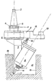
- the drawing shows an embodiment of the invention.
- a base part 1 is provided with a centering cone 2 and a pull pin 3 in order to to be attached to the tool holder of the spindle of a milling machine.
- a collar 4 with a circumferential groove 5 serves to receive the tool unit on one Plate magazine.
- a vertically downwardly projecting holder 7 is attached, to which a drive 8 in the form of a high-frequency motor is attached at an angle of 30 °.
- the output shaft 9 of the drive 8 carries a chuck 10 for a milling tool 11. The arrangement is such that the center point of the rounding of the milling tool tip lies on the axis of the spindle of the milling machine.
- a coupling part 13 is formed on a boom 12 of the base part 1 for connection with a counterpart permanently installed on the milling machine at an appropriate point.
- the drive energy and cooling water for the drive 8 and compressed air is also introduced into the tool unit.
- the cooling water and compressed air inside the base part and through the pivot bearing and the holder 7 into the Drive 8 continued.
- the compressed air occurs on the chuck 10 in the direction parallel to Milling tool 11 from.
- the drive energy flows through a spiral cable, bypassing the pivot bearing 20 from the base part directly into the drive 8.
- a workpiece 14 with a cavity 15 is shown in section.
- the cavity 15 was first worked out with milling tools inserted directly on the spindle; at speeds of up to 8000 min -1 , roughing was carried out and then semi-finishing.
- the tool unit shown is used for fine finishing with up to 60,000 min -1 .
- the drive 8 is not in the way when machining the vertical surface 16 of the cavity.
- its lower end 17 is still conical.
- the cone angle is 30 °, as is the inclination of the drive 8 with respect to the pivot bearing through the angle piece 7.
- the drive 8 is pivoted around with the milling tool 11 by the actuator. The same applies to the other vertical surfaces.
- Using a coarser milling tool 11 can also work out the Cavity can be completed if necessary, especially to create smaller radii than is possible with a milling head, especially with grooves on the vertical Areas or corners between them.
Landscapes
- Engineering & Computer Science (AREA)
- Mechanical Engineering (AREA)
- Jigs For Machine Tools (AREA)
- Multi-Process Working Machines And Systems (AREA)
- Auxiliary Devices For Machine Tools (AREA)
- Finish Polishing, Edge Sharpening, And Grinding By Specific Grinding Devices (AREA)
- Milling Processes (AREA)
- Machine Tool Units (AREA)
Abstract
Description
Mit dem schnellaufenden Fräswerkzeug können an einer normalen Fräsmaschine weitere Bearbeitungen durchgeführt werden, vor allem ein Schlichten.
Damit lassen sich beispielsweise die Formwerkzeuge zur Herstellung von Kunststoffteilen weitgehend auf der Fräsmaschine herstellen. Auch kleine Radien in größerer Tiefe können gearbeitet werden. Ein anschließendes Erodieren ist nur noch in Einzelfällen nötig und nur noch für einen viel kleineren Rest des Materials. Es können wesentliche Verkürzungen der Bearbeitungszeit erzielt werden.
Grundsätzlich sind aber auch beschränkte Möglichkeiten denkbar und ggf. schon vorteilhaft.
Die Anordnung ist so getroffen, daß der Mittelpunkt der Rundung der Fräswerkzeugspitze auf der Achse der Spindel der Fräsmaschine liegt.
Der Hohlraum 15 ist zunächst mit unmittelbar an der Spindel eingesetzten Fräswerkzeugen herausgearbeitet worden; bei Drehzahlen bis zu 8000 min-1 wurde geschruppt und anschließend semigeschlichtet.
Mit der dargestellten Werkzeugeinheit wird mit bis zu 60000 min-1 feingeschlichtet. Wie aus der Zeichnung ersichtlich, ist beim Bearbeiten der senkrechten Fläche 16 des Hohlraumes der Antrieb 8 nicht im Wege. Zu diesem Zweck ist sein unteres Ende 17 noch konisch gestaltet. Der Konuswinkel beträgt 30° wie auch die Schrägstellung des Antriebes 8 gegenüber dem Drehlager durch das Winkelstück 7.
Zur Bearbeitung der gegenüberliegenden senkrechten Fläche 18 wird der Antrieb 8 mit dem Fräswerkzeug 11 durch den Stellantrieb herumgeschwenkt. Entsprechend verhält es sich mit den übrigen senkrechten Flächen.
Claims (2)
- Werkzeugeinheit mit einem Basisteil (1), einem an diesem angeordneten schnellaufenden Antrieb (8) für ein Fräswerkzeug (11), insbesondere einem Schnellfrequenz-Motor, und einem an der Abtriebswelle (9) des Antriebes (8) angeordneten Spannfutter (10) für das Fräswerkzeug (11), die an die Werkzeugaufnahme der Spindel einer Fräsmaschine ansetzbar ist und zugleich an einen an der Fräsmaschine vorgesehenen Anschluß für die Antriebsenergie, für Kühlwasser und für Druckluft, ankuppelbar (13) ist,
dadurch gekennzeichnet,
daß der Antrieb (8) über ein mit der Spindel der Fräsmaschine gleichachsiges Drehlager und einen Halter (7) in einem Winkel zur Achse des Drehlagers an dem Basisteil (1) angebracht ist und durch einen Stellantrieb in dem Drehlager einstellbar ist, daß der Stellantrieb in dem Basisteil (1) angeordnet ist, daß an dem Basisteil (1) ein mit einem an der Fräsmaschine installierten Gegenstück verbindbares Kupplungsteil (13) ausgebildet ist, durch das Antriebsenergie, Kühlwasser und Druckluft der Werkzeugeinheit zuführbar sind, und daß das zugeführte Kühlwasser und die zugeführte Druckluft innerhalb des Basisteils und durch das Drehlager und den Halter (7) hindurch in den Antrieb weitergeführt werden. - Werkzeugeinheit nach Anspruch 1,
dadurch gekennzeichnet,
daß die Antriebsenergie unter Umgehung des Drehlagers durch ein Kabel (20) aus dem Basisteil (1) direkt in den Antrieb (8) geleitet wird.
Applications Claiming Priority (3)
| Application Number | Priority Date | Filing Date | Title |
|---|---|---|---|
| DE19620485A DE19620485A1 (de) | 1996-05-21 | 1996-05-21 | Werkzeugeinheit für eine Fräsmaschine |
| DE19620485 | 1996-05-21 | ||
| EP97107648A EP0808688B2 (de) | 1996-05-21 | 1997-05-09 | Werkzeugeinheit für eine Fräsmaschine |
Related Parent Applications (1)
| Application Number | Title | Priority Date | Filing Date |
|---|---|---|---|
| EP97107648A Division EP0808688B2 (de) | 1996-05-21 | 1997-05-09 | Werkzeugeinheit für eine Fräsmaschine |
Publications (3)
| Publication Number | Publication Date |
|---|---|
| EP1108498A2 true EP1108498A2 (de) | 2001-06-20 |
| EP1108498A3 EP1108498A3 (de) | 2002-03-06 |
| EP1108498B1 EP1108498B1 (de) | 2003-07-30 |
Family
ID=7794930
Family Applications (2)
| Application Number | Title | Priority Date | Filing Date |
|---|---|---|---|
| EP00121544A Expired - Lifetime EP1108498B1 (de) | 1996-05-21 | 1997-05-09 | Werkzeugeinheit für eine Fräsmaschine |
| EP97107648A Expired - Lifetime EP0808688B2 (de) | 1996-05-21 | 1997-05-09 | Werkzeugeinheit für eine Fräsmaschine |
Family Applications After (1)
| Application Number | Title | Priority Date | Filing Date |
|---|---|---|---|
| EP97107648A Expired - Lifetime EP0808688B2 (de) | 1996-05-21 | 1997-05-09 | Werkzeugeinheit für eine Fräsmaschine |
Country Status (5)
| Country | Link |
|---|---|
| EP (2) | EP1108498B1 (de) |
| AT (2) | ATE213193T1 (de) |
| DE (3) | DE19620485A1 (de) |
| ES (1) | ES2201984T3 (de) |
| PT (1) | PT1108498E (de) |
Families Citing this family (13)
| Publication number | Priority date | Publication date | Assignee | Title |
|---|---|---|---|---|
| DE19718396C2 (de) * | 1997-04-30 | 2001-10-31 | Homag Maschinenbau Ag | Erweiterungsaggregat für ein Bearbeitungszentrum |
| DE19916710B4 (de) | 1999-04-14 | 2005-08-04 | Lang, Günter | Werkzeugantriebseinrichtung, insbesondere für Werkzeugmaschinen |
| DE19928839B4 (de) * | 1999-06-24 | 2005-02-17 | Actech Gmbh Advanced Casting Technologies Giessereitechnologie | Spindeladapter für eine stationäre Werkzeugmaschine |
| DE19948335C1 (de) * | 1999-10-07 | 2001-07-05 | Fraunhofer Ges Forschung | Bewegungs- und/oder Positioniervorrichtung |
| EP1268125A4 (de) * | 2000-03-07 | 2003-05-14 | Wildbeam Invest Pty Ltd | Kopf einer werkzeugmaschine, werkzeugmascine und verfahren zum bearbeiten eines objekts |
| DE10012348B4 (de) * | 2000-03-14 | 2006-08-10 | Fraunhofer-Gesellschaft zur Förderung der angewandten Forschung e.V. | Bewegungs- und/oder Positioniervorrichtung |
| DE10044859B4 (de) * | 2000-09-11 | 2005-12-08 | Fraunhofer-Gesellschaft zur Förderung der angewandten Forschung e.V. | Bewegungs- und/oder Positioniervorrichtung |
| DE20017659U1 (de) * | 2000-10-13 | 2001-03-01 | Jäger, Alfred, 61239 Ober-Mörlen | Halterung für eine Motorspindel |
| DE102006026820A1 (de) * | 2006-06-09 | 2007-12-13 | Audi Ag | Fräswerkzeug zum Formstoff-Fräsen von Sandgussformen |
| DE102007041809B4 (de) * | 2007-08-30 | 2017-01-12 | Rolls-Royce Deutschland Ltd & Co Kg | Werkzeughalter für automatischen Werkzeugwechsel |
| US9375816B2 (en) * | 2012-07-11 | 2016-06-28 | Air Turbine Technology, Inc. | Auto changer spindle mounting assembly adapted to drill tap machines |
| CN109719333B (zh) * | 2019-02-15 | 2019-11-19 | 宁波天控五轴数控技术有限公司 | 一种高强度轻量化ac轴直驱双摆铣头 |
| CN112809460A (zh) * | 2020-12-29 | 2021-05-18 | 郑州机械研究所有限公司 | 一种具有刀头自清洁功能的砂轮磨削机床 |
Family Cites Families (11)
| Publication number | Priority date | Publication date | Assignee | Title |
|---|---|---|---|---|
| US2863361A (en) † | 1954-11-09 | 1958-12-09 | Giddings & Lewis | High-speed floor type contour milling machine |
| US3559529A (en) * | 1968-11-12 | 1971-02-02 | Thomas D Vertin | Two-axis machining head for use on a three-axis machine to provide a cutting tool with a five-axis movement |
| CH556708A (de) * | 1973-04-03 | 1974-12-13 | Landis & Gyr Gmbh | Bohreinheit mit auswechselbarem bohrkopf an metallbearbeitungsautomaten. |
| US4077736A (en) * | 1977-04-01 | 1978-03-07 | Kearney & Trecker Corporation | Drill speeder for machine tools |
| IT1173463B (it) † | 1984-03-23 | 1987-06-24 | Andrea Spa D | Testa a fresare nonche' a forare per macchina utensile |
| DE3505538A1 (de) * | 1985-02-18 | 1986-08-21 | Alfing Kessler Sondermaschinen GmbH, 7080 Aalen | Fraeskopf |
| JPS6248437A (ja) * | 1985-08-28 | 1987-03-03 | Dai Showa Seiki Kk | 回転工具取り付け用アタツチメント |
| JPS62181849A (ja) * | 1986-02-04 | 1987-08-10 | Honda Motor Co Ltd | 回転工具用ホルダ装置 |
| US4795293A (en) * | 1986-09-05 | 1989-01-03 | Mizoguchi Iron Works & Co., Ltd. | Unit for mounting a cutting tool |
| DE9405918U1 (de) † | 1994-04-09 | 1994-06-30 | Marciniak, Heinz, 58455 Witten | Werkzeugsystem für Werkzeugmaschinen |
| US5697739A (en) * | 1995-06-06 | 1997-12-16 | Kennametal Inc. | Angle spindle attachment |
-
1996
- 1996-05-21 DE DE19620485A patent/DE19620485A1/de not_active Withdrawn
-
1997
- 1997-05-09 DE DE59710522T patent/DE59710522D1/de not_active Expired - Lifetime
- 1997-05-09 AT AT97107648T patent/ATE213193T1/de not_active IP Right Cessation
- 1997-05-09 PT PT00121544T patent/PT1108498E/pt unknown
- 1997-05-09 EP EP00121544A patent/EP1108498B1/de not_active Expired - Lifetime
- 1997-05-09 DE DE59706358T patent/DE59706358D1/de not_active Expired - Fee Related
- 1997-05-09 ES ES00121544T patent/ES2201984T3/es not_active Expired - Lifetime
- 1997-05-09 EP EP97107648A patent/EP0808688B2/de not_active Expired - Lifetime
- 1997-05-09 AT AT00121544T patent/ATE246069T1/de active
Also Published As
| Publication number | Publication date |
|---|---|
| ATE246069T1 (de) | 2003-08-15 |
| PT1108498E (pt) | 2003-12-31 |
| EP1108498B1 (de) | 2003-07-30 |
| EP1108498A3 (de) | 2002-03-06 |
| EP0808688A1 (de) | 1997-11-26 |
| ES2201984T3 (es) | 2004-04-01 |
| ATE213193T1 (de) | 2002-02-15 |
| EP0808688B2 (de) | 2005-02-02 |
| DE59706358D1 (de) | 2002-03-28 |
| EP0808688B1 (de) | 2002-02-13 |
| DE19620485A1 (de) | 1997-11-27 |
| DE59710522D1 (de) | 2003-09-04 |
Similar Documents
| Publication | Publication Date | Title |
|---|---|---|
| DE10308292B4 (de) | Verfahren zum Rundschleifen bei der Herstellung von Werkzeugen aus Hartmetall und Rundschleifmaschine zum Schleifen von zylindrischen Ausgangskörpern bei der Herstellung von Werkzeugen aus Hartmetall | |
| EP0483064B1 (de) | Bearbeitungszentrum zum Schleifen von Werkstücken mit komplex geformten Oberflächen | |
| EP1427568B1 (de) | Verfahren und vorrichtung zum schleifen von zentrischen lagerstellen von kurbelwellen | |
| DE29723542U1 (de) | Vorrichtung zur Bearbeitung optischer Linsen | |
| EP1108498B1 (de) | Werkzeugeinheit für eine Fräsmaschine | |
| DE19921785B4 (de) | Verfahren zum Schleifen von konvexen Laufflächen und Außendurchmessern an Wellen mit wenigstens einem scheibenförmigen Wellenabschnitt sowie Schleifmaschine zur Durchführung des Verfahrens | |
| DE102005021639A1 (de) | Hochleistungs-Fräs- und Drehmaschine sowie Verfahren zur Bearbeitung von Brillengläsern | |
| DE2937976C2 (de) | Maschine zum Schleifen oder Fräsen von konvexen und/oder konkaven sphärischen Flächen | |
| DE19750428A1 (de) | Verfahren und Vorrichtung zum beidseitigen Polieren optischer Linsen | |
| DE19756280C2 (de) | Kehlmaschine sowie Werkzeug für eine Kehlmaschine | |
| EP1479495A2 (de) | Verfahren und Bearbeitungsaggregat zum Bündigfräsen und Abziehen eines an plattenförmige Werkstücke angebrachten Kantenbandes | |
| EP2130644A2 (de) | Vorrichtung zum Bearbeiten eines Werkstückes | |
| DE2827543A1 (de) | Vorrichtung zum feinschleifen | |
| EP2161099B1 (de) | Schleifmaschine | |
| DE8900899U1 (de) | Vorrichtung zum Entgraten, Abfasen und Abrunden | |
| DE2030851B2 (de) | Maschine zum Schleifen von mit einer Planschulter versehenen zylindrischen Werkstückbohrungen | |
| DE10011454A1 (de) | Schleifvorrichtung | |
| DE19809353C2 (de) | Verfahren zum beidseitigen Schleifen von Linsen und Vorrichtung zum Durchführen des Verfahrens | |
| DE29623469U1 (de) | Werkzeugeinheit für eine Fräsmaschine | |
| DE29521396U1 (de) | Schleifkopf zum Bearbeiten von Glasscheiben | |
| DE10057228B4 (de) | Verfahren zum Schleifen von optischen Linsen mittels Ring- und Formwerkzeugen und Vorrichtung zur Durchführung des Verfahrens | |
| DE10205463A1 (de) | Vorrichtung zum Bearbeiten eines Drehteils | |
| DE29615719U1 (de) | Tischmaschine zur Kantenbearbeitung an Werkstücken von oben | |
| DE3611103A1 (de) | Schleifmaschine | |
| DE1955787U (de) | Schleifvorrichtung fuer elektroden. |
Legal Events
| Date | Code | Title | Description |
|---|---|---|---|
| PUAI | Public reference made under article 153(3) epc to a published international application that has entered the european phase |
Free format text: ORIGINAL CODE: 0009012 |
|
| AC | Divisional application: reference to earlier application |
Ref document number: 808688 Country of ref document: EP |
|
| AK | Designated contracting states |
Kind code of ref document: A2 Designated state(s): AT CH DE ES FR GB IT LI NL PT |
|
| AX | Request for extension of the european patent |
Free format text: SI PAYMENT 20001026 |
|
| PUAL | Search report despatched |
Free format text: ORIGINAL CODE: 0009013 |
|
| AK | Designated contracting states |
Kind code of ref document: A3 Designated state(s): AT CH DE ES FR GB IT LI NL PT |
|
| AX | Request for extension of the european patent |
Free format text: SI PAYMENT 20001026 |
|
| 17P | Request for examination filed |
Effective date: 20020222 |
|
| AKX | Designation fees paid |
Free format text: AT CH DE ES FR GB IT LI NL PT |
|
| AXX | Extension fees paid |
Free format text: SI PAYMENT 20001026 |
|
| GRAH | Despatch of communication of intention to grant a patent |
Free format text: ORIGINAL CODE: EPIDOS IGRA |
|
| GRAH | Despatch of communication of intention to grant a patent |
Free format text: ORIGINAL CODE: EPIDOS IGRA |
|
| GRAA | (expected) grant |
Free format text: ORIGINAL CODE: 0009210 |
|
| AC | Divisional application: reference to earlier application |
Ref document number: 0808688 Country of ref document: EP Kind code of ref document: P |
|
| AK | Designated contracting states |
Designated state(s): AT CH DE ES FR GB IT LI NL PT |
|
| AX | Request for extension of the european patent |
Extension state: SI |
|
| REG | Reference to a national code |
Ref country code: GB Ref legal event code: FG4D Free format text: NOT ENGLISH |
|
| REG | Reference to a national code |
Ref country code: CH Ref legal event code: EP |
|
| REF | Corresponds to: |
Ref document number: 59710522 Country of ref document: DE Date of ref document: 20030904 Kind code of ref document: P |
|
| GBT | Gb: translation of ep patent filed (gb section 77(6)(a)/1977) |
Effective date: 20031110 |
|
| ET | Fr: translation filed | ||
| REG | Reference to a national code |
Ref country code: ES Ref legal event code: FG2A Ref document number: 2201984 Country of ref document: ES Kind code of ref document: T3 |
|
| PLBE | No opposition filed within time limit |
Free format text: ORIGINAL CODE: 0009261 |
|
| STAA | Information on the status of an ep patent application or granted ep patent |
Free format text: STATUS: NO OPPOSITION FILED WITHIN TIME LIMIT |
|
| 26N | No opposition filed |
Effective date: 20040504 |
|
| REG | Reference to a national code |
Ref country code: CH Ref legal event code: PUE Owner name: ALFRED JAEGER GMBH Free format text: JAEGER, ALFRED#SIEMENSSTRASSE 8#61239 OBER-MOERLEN (DE) -TRANSFER TO- ALFRED JAEGER GMBH#SIEMENSSTRASSE 8#61239 OBER-MOERLEN (DE) |
|
| REG | Reference to a national code |
Ref country code: GB Ref legal event code: 732E |
|
| NLS | Nl: assignments of ep-patents |
Owner name: ALFRED JAEGER GMBH Effective date: 20080128 |
|
| REG | Reference to a national code |
Ref country code: FR Ref legal event code: TP |
|
| REG | Reference to a national code |
Ref country code: PT Ref legal event code: PC4A Owner name: ALFRED JAEGER GMBH, DE Effective date: 20090407 |
|
| PGFP | Annual fee paid to national office [announced via postgrant information from national office to epo] |
Ref country code: PT Payment date: 20110427 Year of fee payment: 15 Ref country code: CH Payment date: 20110525 Year of fee payment: 15 Ref country code: FR Payment date: 20110603 Year of fee payment: 15 Ref country code: ES Payment date: 20110524 Year of fee payment: 15 |
|
| PGFP | Annual fee paid to national office [announced via postgrant information from national office to epo] |
Ref country code: GB Payment date: 20110523 Year of fee payment: 15 Ref country code: NL Payment date: 20110524 Year of fee payment: 15 Ref country code: AT Payment date: 20110520 Year of fee payment: 15 |
|
| PGFP | Annual fee paid to national office [announced via postgrant information from national office to epo] |
Ref country code: IT Payment date: 20110527 Year of fee payment: 15 |
|
| PGFP | Annual fee paid to national office [announced via postgrant information from national office to epo] |
Ref country code: DE Payment date: 20110801 Year of fee payment: 15 |
|
| REG | Reference to a national code |
Ref country code: PT Ref legal event code: MM4A Free format text: LAPSE DUE TO NON-PAYMENT OF FEES Effective date: 20121109 |
|
| REG | Reference to a national code |
Ref country code: NL Ref legal event code: V1 Effective date: 20121201 |
|
| REG | Reference to a national code |
Ref country code: CH Ref legal event code: PL |
|
| REG | Reference to a national code |
Ref country code: AT Ref legal event code: MM01 Ref document number: 246069 Country of ref document: AT Kind code of ref document: T Effective date: 20120509 |
|
| GBPC | Gb: european patent ceased through non-payment of renewal fee |
Effective date: 20120509 |
|
| PG25 | Lapsed in a contracting state [announced via postgrant information from national office to epo] |
Ref country code: AT Free format text: LAPSE BECAUSE OF NON-PAYMENT OF DUE FEES Effective date: 20120509 Ref country code: LI Free format text: LAPSE BECAUSE OF NON-PAYMENT OF DUE FEES Effective date: 20120531 Ref country code: CH Free format text: LAPSE BECAUSE OF NON-PAYMENT OF DUE FEES Effective date: 20120531 |
|
| PG25 | Lapsed in a contracting state [announced via postgrant information from national office to epo] |
Ref country code: PT Free format text: LAPSE BECAUSE OF NON-PAYMENT OF DUE FEES Effective date: 20121109 Ref country code: IT Free format text: LAPSE BECAUSE OF NON-PAYMENT OF DUE FEES Effective date: 20120509 |
|
| REG | Reference to a national code |
Ref country code: FR Ref legal event code: ST Effective date: 20130131 |
|
| REG | Reference to a national code |
Ref country code: DE Ref legal event code: R119 Ref document number: 59710522 Country of ref document: DE Effective date: 20121201 |
|
| PG25 | Lapsed in a contracting state [announced via postgrant information from national office to epo] |
Ref country code: NL Free format text: LAPSE BECAUSE OF NON-PAYMENT OF DUE FEES Effective date: 20121201 |
|
| PG25 | Lapsed in a contracting state [announced via postgrant information from national office to epo] |
Ref country code: GB Free format text: LAPSE BECAUSE OF NON-PAYMENT OF DUE FEES Effective date: 20120509 Ref country code: FR Free format text: LAPSE BECAUSE OF NON-PAYMENT OF DUE FEES Effective date: 20120531 |
|
| PG25 | Lapsed in a contracting state [announced via postgrant information from national office to epo] |
Ref country code: DE Free format text: LAPSE BECAUSE OF NON-PAYMENT OF DUE FEES Effective date: 20121201 |
|
| REG | Reference to a national code |
Ref country code: ES Ref legal event code: FD2A Effective date: 20130821 |
|
| PG25 | Lapsed in a contracting state [announced via postgrant information from national office to epo] |
Ref country code: ES Free format text: LAPSE BECAUSE OF NON-PAYMENT OF DUE FEES Effective date: 20120510 |