EP1108568A2 - Verfahren und Vorrichtung zur Übertragung von Dateien über den Betriebszustand eines Reifen - Google Patents
Verfahren und Vorrichtung zur Übertragung von Dateien über den Betriebszustand eines Reifen Download PDFInfo
- Publication number
- EP1108568A2 EP1108568A2 EP00122282A EP00122282A EP1108568A2 EP 1108568 A2 EP1108568 A2 EP 1108568A2 EP 00122282 A EP00122282 A EP 00122282A EP 00122282 A EP00122282 A EP 00122282A EP 1108568 A2 EP1108568 A2 EP 1108568A2
- Authority
- EP
- European Patent Office
- Prior art keywords
- data
- tire condition
- data message
- transmitter
- controller
- Prior art date
- Legal status (The legal status is an assumption and is not a legal conclusion. Google has not performed a legal analysis and makes no representation as to the accuracy of the status listed.)
- Granted
Links
- 238000000034 method Methods 0.000 title claims description 22
- 230000033001 locomotion Effects 0.000 claims description 40
- 230000005540 biological transmission Effects 0.000 claims description 17
- 230000004044 response Effects 0.000 claims description 14
- 230000003213 activating effect Effects 0.000 claims description 4
- 230000006870 function Effects 0.000 description 15
- 238000005259 measurement Methods 0.000 description 6
- 230000004913 activation Effects 0.000 description 5
- 238000004891 communication Methods 0.000 description 5
- 238000012544 monitoring process Methods 0.000 description 5
- 238000010586 diagram Methods 0.000 description 4
- 125000004122 cyclic group Chemical group 0.000 description 2
- 238000012986 modification Methods 0.000 description 2
- 230000004048 modification Effects 0.000 description 2
- 230000000737 periodic effect Effects 0.000 description 2
- 230000000007 visual effect Effects 0.000 description 2
- 102100029716 DnaJ homolog subfamily A member 3, mitochondrial Human genes 0.000 description 1
- 101000866012 Homo sapiens DnaJ homolog subfamily A member 3, mitochondrial Proteins 0.000 description 1
- 230000003111 delayed effect Effects 0.000 description 1
- 230000001419 dependent effect Effects 0.000 description 1
- 238000001514 detection method Methods 0.000 description 1
- 230000000694 effects Effects 0.000 description 1
- 238000004519 manufacturing process Methods 0.000 description 1
- 239000011159 matrix material Substances 0.000 description 1
- 230000008569 process Effects 0.000 description 1
- 238000012545 processing Methods 0.000 description 1
- 230000007704 transition Effects 0.000 description 1
Images


Classifications
-
- B—PERFORMING OPERATIONS; TRANSPORTING
- B60—VEHICLES IN GENERAL
- B60C—VEHICLE TYRES; TYRE INFLATION; TYRE CHANGING; CONNECTING VALVES TO INFLATABLE ELASTIC BODIES IN GENERAL; DEVICES OR ARRANGEMENTS RELATED TO TYRES
- B60C23/00—Devices for measuring, signalling, controlling, or distributing tyre pressure or temperature, specially adapted for mounting on vehicles; Arrangement of tyre inflating devices on vehicles, e.g. of pumps or of tanks; Tyre cooling arrangements
- B60C23/02—Signalling devices actuated by tyre pressure
- B60C23/04—Signalling devices actuated by tyre pressure mounted on the wheel or tyre
- B60C23/0408—Signalling devices actuated by tyre pressure mounted on the wheel or tyre transmitting the signals by non-mechanical means from the wheel or tyre to a vehicle body mounted receiver
- B60C23/0415—Automatically identifying wheel mounted units, e.g. after replacement or exchange of wheels
- B60C23/0416—Automatically identifying wheel mounted units, e.g. after replacement or exchange of wheels allocating a corresponding wheel position on vehicle, e.g. front/left or rear/right
-
- B—PERFORMING OPERATIONS; TRANSPORTING
- B60—VEHICLES IN GENERAL
- B60C—VEHICLE TYRES; TYRE INFLATION; TYRE CHANGING; CONNECTING VALVES TO INFLATABLE ELASTIC BODIES IN GENERAL; DEVICES OR ARRANGEMENTS RELATED TO TYRES
- B60C23/00—Devices for measuring, signalling, controlling, or distributing tyre pressure or temperature, specially adapted for mounting on vehicles; Arrangement of tyre inflating devices on vehicles, e.g. of pumps or of tanks; Tyre cooling arrangements
- B60C23/02—Signalling devices actuated by tyre pressure
- B60C23/04—Signalling devices actuated by tyre pressure mounted on the wheel or tyre
- B60C23/0408—Signalling devices actuated by tyre pressure mounted on the wheel or tyre transmitting the signals by non-mechanical means from the wheel or tyre to a vehicle body mounted receiver
- B60C23/0422—Signalling devices actuated by tyre pressure mounted on the wheel or tyre transmitting the signals by non-mechanical means from the wheel or tyre to a vehicle body mounted receiver characterised by the type of signal transmission means
- B60C23/0433—Radio signals
-
- B—PERFORMING OPERATIONS; TRANSPORTING
- B60—VEHICLES IN GENERAL
- B60C—VEHICLE TYRES; TYRE INFLATION; TYRE CHANGING; CONNECTING VALVES TO INFLATABLE ELASTIC BODIES IN GENERAL; DEVICES OR ARRANGEMENTS RELATED TO TYRES
- B60C23/00—Devices for measuring, signalling, controlling, or distributing tyre pressure or temperature, specially adapted for mounting on vehicles; Arrangement of tyre inflating devices on vehicles, e.g. of pumps or of tanks; Tyre cooling arrangements
- B60C23/02—Signalling devices actuated by tyre pressure
- B60C23/04—Signalling devices actuated by tyre pressure mounted on the wheel or tyre
- B60C23/0408—Signalling devices actuated by tyre pressure mounted on the wheel or tyre transmitting the signals by non-mechanical means from the wheel or tyre to a vehicle body mounted receiver
- B60C23/0422—Signalling devices actuated by tyre pressure mounted on the wheel or tyre transmitting the signals by non-mechanical means from the wheel or tyre to a vehicle body mounted receiver characterised by the type of signal transmission means
- B60C23/0433—Radio signals
- B60C23/0447—Wheel or tyre mounted circuits
- B60C23/0455—Transmission control of wireless signals
- B60C23/0462—Structure of transmission protocol
-
- B—PERFORMING OPERATIONS; TRANSPORTING
- B60—VEHICLES IN GENERAL
- B60C—VEHICLE TYRES; TYRE INFLATION; TYRE CHANGING; CONNECTING VALVES TO INFLATABLE ELASTIC BODIES IN GENERAL; DEVICES OR ARRANGEMENTS RELATED TO TYRES
- B60C23/00—Devices for measuring, signalling, controlling, or distributing tyre pressure or temperature, specially adapted for mounting on vehicles; Arrangement of tyre inflating devices on vehicles, e.g. of pumps or of tanks; Tyre cooling arrangements
- B60C23/02—Signalling devices actuated by tyre pressure
- B60C23/04—Signalling devices actuated by tyre pressure mounted on the wheel or tyre
- B60C23/0408—Signalling devices actuated by tyre pressure mounted on the wheel or tyre transmitting the signals by non-mechanical means from the wheel or tyre to a vehicle body mounted receiver
- B60C23/0422—Signalling devices actuated by tyre pressure mounted on the wheel or tyre transmitting the signals by non-mechanical means from the wheel or tyre to a vehicle body mounted receiver characterised by the type of signal transmission means
- B60C23/0433—Radio signals
- B60C23/0447—Wheel or tyre mounted circuits
- B60C23/0455—Transmission control of wireless signals
- B60C23/0464—Transmission control of wireless signals to avoid signal interference
Definitions
- the present invention relates to a tire condition sensing apparatus and, more particularly, to an apparatus and method for transmitting data in a tire condition sensing system.
- a system typically includes a pressure switch, an internal power source, and a communications link that provides the tire pressure information from a location at each vehicle tire to a central receiver, which may be mounted on the vehicle dashboard.
- the communications link may be a wired or wireless link.
- tire pressure monitoring systems are disclosed in U.S. Patent No. 4,316,176, U.S. Patent No. 5,573,610, U.S. Patent No. 5,600,301, U.S. Patent No. 5,602,524, U.S. Patent No. 5,612,671 and U.S. Patent No. 5,656,993.
- One aspect of the present invention provides a tire condition sensing apparatus that includes a tire condition sensor for sensing a tire condition.
- a transmitter transmits a data message having a plurality of data locations for accommodating data.
- a controller is electrically connected with the tire condition sensor and the transmitter. The controller controls the transmitter to transmit data in selected data locations of the data message based on an identification code of the apparatus.
- a tire condition sensing system that includes a plurality of tire condition transmitter modules.
- Each of the modules has a unique identification code and includes a tire condition sensor for sensing a condition of an associated vehicle tire.
- Each module also includes a transmitter which, when activated, transmits a data message having a plurality of data locations for accommodating data.
- Each module also includes a controller electrically connected with the tire condition sensor and the transmitter of the corresponding module. The controller controls the associated transmitter to transmit tire condition data in data locations of the data message selected based on the unique identification code of the corresponding module.
- Still another aspect of the present invention provides a tire condition sensing apparatus that includes a tire condition sensor for sensing a tire condition.
- a transmitter transmits a data message having a plurality of data locations for accommodating data.
- a controller is electrically connected with the tire condition sensor and the transmitter. The controller controls the transmitter to transmit tire condition data in selected data locations of the data message based on a parameter associated with the apparatus.
- Yet another aspect of the present invention provides a method of transmitting a data message from a tire condition module having an identification code.
- the method includes the steps of sensing a condition of a tire and determining random data locations of a data message based on the identification code of the tire condition module.
- a data message is transmitted, in which tire condition data indicative of the sensed tire condition is provided in the determined random data location of the data message.
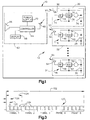
- Fig. 1 schematically illustrates a vehicle 10 equipped with a tire condition monitoring system 12 in accordance with the present invention.
- the system 12 includes a plurality of tire condition sensor modules 14, 16, and 18 for sensing one or more tire conditions of associated vehicle tires 20, 22, and 24, respectively. While for purposes of brevity three modules 14, 16, and 18 are illustrated, there typically is one module associated with each vehicle tire, including any spare tire(s) of the vehicle 10.
- Each module 14, 16, 18 includes a respective internal power supply 26, 28, 30 that supplies electrical energy to various circuit components of each associated module.
- each power supply 26, 28, 30 is electrically connected to a motion detector 32, 34, 36, respectively.
- Each power supply 26, 28, 30 also is electrically connected with a controller, such as an application specific integrated circuit (ASIC) 38, 40, 42, and to an RF transmitter 44, 46, 48, respectively.
- ASIC application specific integrated circuit
- Each motion detector 32, 34, 36 provides a motion signal to the associated ASIC 38, 40, 42 having an electrical characteristic or state that indicates movement of the associated vehicle tire 20, 22, 24.
- Each ASIC 38, 40, 42 has a plurality of operating modes responsive to the motion signal from its associated motion detector 32, 34, 36.
- Each ASIC 38, 40, 42 controls the operation of each module 14, 16, 18 according to the its current operating mode.
- each ASIC 38, 40, 42 includes one or more sensors operative to sense one or more conditions of each associated vehicle tire 20, 22, 24 and/or operating parameters of the associated module itself. The sensors provide sensor signals indicative of the condition sensed thereby. The associated ASIC 38, 40, 42 processes the sensor signals to determine desired tire condition data and/or diagnostic information. Each ASIC 38, 40, 42 provides tire condition data and/or diagnostic information to its corresponding transmitter 44, 46, 48. Each transmitter 44, 46, 48, under the control of its respective ASIC 38, 40, 42, provides an encoded data message signal to an associated antenna 50, 52 and 54 indicative of the data received from the ASIC.
- the antenna 50, 52, 54 transmits or broadcasts the data message as an RF signal through free space, indicated respectively at 51, 53, 55.
- the data message may include an indication of tire condition, diagnostic information for the associated module, an identification (ID) code of the module, a tire ID code indicating the location of the module relative to the vehicle, etc.
- the RF signals 51, 53, and 55 from the modules 14, 16, and 18 are received at an antenna 60 of the receiver module 62.
- the received signals are decoded by appropriate circuitry of the module 62 and provided to a controller 64.
- the controller 64 may include the circuitry that decodes or demodulates the signals.
- the decoder circuitry may be external to the controller 64 and connected between the antenna 60 and the controller.
- the controller 64 is a microcontroller or microcomputer configured for receiving the tire condition data signals, decoding and processing the received signals, and providing an indication of the received tire condition information.
- the controller 64 is electrically connected to a speaker 66 for, when appropriate, providing an audible indication, e.g., a warning signal, based on the information contained in the data messages.
- the controller 64 is connected to a display 68 that provides a visual indication of the received tire condition and diagnostic information.
- the display 68 for example, may be an LED or LCD display of known configuration for displaying detailed tire condition information for each vehicle tire as sensed by the tire condition sensor modules 14, 16, and 18.
- the controller 64, the associated display 68, and speaker 66 are powered by a power supply 70.
- the power supply may be a vehicle battery, such as when the receiver module 62 is mounted within the vehicle 10.
- the receiver module 62 alternatively might be powered by an internal power supply. It is also contemplated that the receiver module 62 may be a hand-held, portable device or fob that a vehicle occupant or other individual may carry to obtain an audible and/or visual indication of the tire condition and/or diagnostic information.
- the communications link between the modules 14, 16, and 18 and the receiver 62 has been described as being an RF link, other wireless communication links could be used in accordance with the present invention.
- Fig. 2 illustrates the tire condition sensor module 14 of Fig. 1 in accordance with an exemplary embodiment of the present invention.
- Identical reference numbers refer to parts of the module 14 previously identified with respect to Fig. 1.
- the sensor module 14 may be integrated in a single package, operating as a stand alone unit for use with the associated vehicle tire (e.g., 20 of Fig. 1).
- the sensor module 14 includes sensor components which are operative to sense various conditions of the vehicle tire and/or to obtain diagnostic information of the module 14.
- the tire conditions include tire pressure and temperature and the diagnostic information includes battery voltage. It is also contemplated that other parameters of the tire and/or of the module also may be monitored in accordance with the present invention.
- the transmitter 44 of the module 14 broadcasts a data message signal indicative of the sensed parameters, such as in a serial data format, for receipt by the central receiver (e.g., 62 of Fig. 1).
- the motion detector 32 detects movement of the associated vehicle tire (e.g., 20 of Fig. 1), such as in response to rotation or vibration thereof.
- the motion detector 32 is connected to a controller 72 of the ASIC 38 via connection 74.
- the motion detector 32 provides a signal to the controller 72 in response to the detected movement.
- the motion detector 32 is in the form of a normally open centrifugal switch that closes upon the associated vehicle tire 20 rotating at a predetermined rate.
- the centrifugal switch closes when the associated tire rotates at a rate corresponding to a vehicle speed of about 10 mph or greater.
- the centrifugal switch When the centrifugal switch is closed, it provides a motion signal to the controller 72, such as a logic HIGH signal at a predetermined voltage.
- the logic HIGH motion signal indicates that the associated vehicle tire (e.g., 20 of Fig. 1) is rotating at a rate corresponding to at least the predetermined vehicle speed.
- a logic LOW motion signal of a predetermined voltage e.g. zero volts, is provided to the controller 72. This indicates either the absence of vehicle movement or movement at a speed less than the predetermined vehicle speed.
- the controller 72 may be a microcontroller, a microprocessor, a state machine, discrete components, another ASIC or any combination thereof.
- the controller 72 controls operation of the module 14.
- the function of the controller 72 could be implemented as hardware and/or software.
- the controller 72 sets an operating mode or state of the module 14 in response to the motion signal received over 74 as well as in response to other criteria.
- the controller 72 tracks the state of various flag conditions that vary based on monitored parameters, such as pressure, temperature, battery voltage and motion of the associated vehicle tire.
- the controller 72 controls transitions between operating modes according to the particular value of each of the flag conditions.
- the controller 72 also controls the timing of tire condition measurements and the timing transmission of data messages.
- the controller 72 has an output 75 connected to a control switch 76 for controlling activation of other components of the sensor module 14.
- the control switch 76 has an input electrically connected to the power supply 26, such as through an appropriate filter and/or voltage regulator (not shown).
- the switch 76 also has an output connected to various circuit components located within the ASIC 38. The circuit components could, in accordance with the present invention, be located external to the ASIC 38.
- switches 76 While, for purposes of brevity, a single switch 76 is illustrated as connecting components to the power supply 26, the controller 72 alternatively could control each of the components through separate switches or an appropriate switching matrix.
- the switches may be located external to the controller 72, such as shown with switch 76 in Fig. 2. Alternatively, one or more switches may be integrated as part of the controller 72 so as to provide desired electrical energy to selected components.
- a pressure sensor 78 that is operative to sense tire pressure of the associated vehicle tire (e.g., 20 of Fig. 1) is connected to the switch 76.
- the pressure sensor 78 provides a tire pressure signal 80 to an input of a multiplexer circuit 82 indicative of the sensed tire pressure.
- the pressure sensor 78 provides the tire pressure signal 80 when activated by the control switch 76.
- the pressure sensor 78 may be an analog pressure sensing device, such as a Wheatstone bridge, that provides a signal having an electrical characteristic (e.g., a voltage differential) indicating an absolute relative pressure detected by the sensor 78.
- the pressure sensor 78 is capable of sensing pressure within a range, for example, from about 50 kPa to about 640 kPa over a wide temperature range.
- a temperature sensor 84 also is connected to the switch 76 and to an input of the multiplexer circuit 82.
- the temperature sensor 84 provides a signal 86 to the multiplexer circuit 82 having an electrical characteristic indicative of the sensed temperature of the associated vehicle tire.
- the controller 72 controls operation of the temperature sensor 84 through activation of the control switch 76.
- a battery voltage sensor 88 is electrically connected between the internal power supply 26 and an input of the multiplexer circuit 82.
- the voltage sensor 88 samples the voltage of the power supply 26 upon activation of the control switch 76 by the controller 72.
- the voltage sensor 88 provides a battery voltage signal 90 to the multiplexer circuit 82 having an electrical characteristic indicative of the sensed voltage.
- the value of the battery voltage signal 90 after each broadcast provides a good indication of the electrical energy available in the power supply 26.
- the multiplexer circuit 82 thus receives parallel input signals 80, 86 and 90 from the respective sensing components 78, 84 and 88.
- the multiplexer circuit 82 provides a multiplexed serial output signal 92, indicative of the sensed parameters from each of the sensors 78, 84 and 88.
- the controller 72 also could be connected to the multiplexer circuit 82 to further control the multiplexing function thereof.
- the multiplexed data signal 92 is provided to an analog-to-digital converter (A/D) 94 which provides a digitized output signal 96 to a calibration function 98.
- A/D analog-to-digital converter
- the signals from the sensors 78, 84, and 88 could be digitized prior to being provided to the multiplexer circuit 82.
- the calibration function 98 which may be hardware and/or software, is configured to de-multiplex the digitized data signal 96 received from ADC 94 and calibrate the data into a readable format for the controller 72.
- the calibration function 98 may include a plurality of pressure curves, temperature curves and/or look-up tables from which calibrated temperature and pressure values are determined based on the information contained in the digitized data signal 96.
- the look-up table and curves are derived from empirical data over a wide range of temperature and pressure for the particular pressure and temperature sensors 78 and 84 being used.
- the calibration function 98 also includes a look-up table for converting the digitized voltage signal into a calibrated voltage value in a useable format.
- the calibration block 98 provides a calibrated output signal 100 to another input of the controller 72.
- the signal 100 has a characteristic or value indicative of each of the sensed parameters, e.g., pressure, temperature, and battery voltage.
- the controller 72 receives the calibrated data signal 100 and stores at least some of the received data in appropriate memory (not shown).
- the controller 72 also is programmed with a unique identification (ID) code for the transmitter 44 of the module 14 and, optionally, a tire ID code.
- ID unique identification
- the transmitter ID code is set at the manufacturer.
- the tire ID code may be set at the factory or by a technician who installs the module.
- the tire ID code is set to indicate the tire location of the module 14 relative to the vehicle.
- the controller 72 is electrically connected with the transmitter 44 for controlling transmissions of the data message through the associated antenna 50.
- the broadcast of the data message signal occurs at selected times based on the particular operating mode of the ASIC 38.
- the controller 72 determines the operating mode of the ASIC 38 in response to both the motion signal received over connection 74 and in response to the sensed parameters indicated by the calibrated output signal 100.
- the controller 72 has a first operating mode, hereinafter referred to as the normal operating mode, in response to the motion signal indicating at least a predetermined rate of rotation of the associated vehicle tire, i.e., the centrifugal switch is closed.
- the controller 72 controls the switch 76 to effect periodic activation of the tire condition sensors 78, 84 and 88 as well as the other circuit components 82, 94 and 98 of the ASIC 38.
- sensors 78, 84 and 88 periodically sense the tire condition of the associated vehicle tire at a predetermined rate, such as about once every four to ten seconds.
- the controller 72 controls the RF transmitter 44 to broadcast the data message signal.
- the broadcast of each data message signal occurs intermittently at random time intervals within a variable time window, such as ranging from about three to about five minutes. This helps to reduce the overlap and interference of data messages from other sensor modules (e.g., 16, 18 of Fig. 1).
- the controller 72 controls the sensor module 14 to operate in a second, different operating mode.
- the second operating mode is referred to as a sleep mode.
- the controller 72 controls the switch 76 to activate each of the tire condition sensors 78, 84, and 88 so as to sense their respective parameters at a periodic rate that is substantially slower than the rate at which corresponding tire conditions are sensed when in the normal operating mode.
- the sensors 78, 84, and 88 are controlled to sense the tire conditions about every 15 minutes.
- the tire condition data signal is broadcast in the sleep mode only after one or more of the sensed tire conditions is determined to be below a predetermined threshold.
- the controller 72 controls the transmitter 44 to broadcast the tire condition data signal only after first determining that the sensed tire pressure is below a predetermined threshold, such as about 220kPa or about 18 psi.
- the broadcasting alternatively could be based on determining that the sensed temperature is at or above some predetermined level or that the sensed battery voltage is below a voltage threshold.
- the sleep mode helps to conserve the energy of the internal power supply 26 when the vehicle is parked or otherwise not being used.
- the sleep mode advantageously still provides for relatively frequent measurements of the tire condition so that upon determining the occurrence of, for example, a low tire pressure condition, this information is provided to the driver upon starting the vehicle as key-on-status information.
- the restricted broadcasts in the sleep mode further help to reduce interference with other RF communication links of the vehicle, such as a remote keyless entry system, that typically occur when the vehicle is stationary.
- Other operating modes also may be used to control the frequency of parameter measurements as well as transmission of the data message signals.
- a data message 120 has a time interval, indicated at 122.
- the data message 120 is subdivided into a plurality of data frames, such as five, indicated as FRAME 1 through FRAME 5.
- the time interval of FRAME 1 is indicated at 124.
- Each frame preferably has the same time interval.
- Each data frame is further divided into a plurality of time slots 126 into which desired data may be provided. In this example, there are four time slots per frame, although other numbers of time slots per frame could be used.
- the grouping of data that is provided in a time slot 126 is hereinafter referred to as a data packet.
- the duration of a time slot is indicated at 128 and the duration of a data packet is indicated at 130.
- Fig. 4 illustrates a functional example of a data packet 130 that extends an interval indicated at 132.
- Each data packet 126 in a data message includes a plurality of data bits that contains selected data.
- the data packet 130 includes a start pulse followed by a preamble that contains synchronization information for the data packet.
- the data packet contains calibrated data indicative of one or more of the sensed parameters, including at least one of temperature, battery voltage, and pressure.
- the data packet 126 also contains data indicating the type of calibrated data being indicated in the data packet.
- the data packet 130 contains data corresponding to the tire ID code and the transmitter ID code.
- the tire position ID code may comprise three bits while the transmitter ID code may comprise 19 bits.
- the data packet 130 includes data bits indicating the current operating mode of the transmitter.
- data bits are provided to indicate temperature status, such as whether the sensed temperature is normal, invalid, a low temperature, or a high temperature. Error bits also may be provided for indicating a low battery condition or other internal errors detected by the controller at the sensor module.
- a cyclic redundancy check (CRC) of the proceeding data also is provided in the data packet 130 for error detection.
- CRC cyclic redundancy check
- each data frame contains two data packets located in selected data slots.
- a data packet is positioned in the first slot of each frame.
- the second data packet in each frame of the data message is located in a time slot randomly selected from the three remaining slots per frame per data message.
- the random location for the second data packet in a frame is determined based on a selected parameter of the module 14.
- the parameter for example, could be the transmitter ID code or a sensed tire condition, such as pressure, temperature, wheel speed, etc.
- the time slot selection for the second data packet is determined by a random number generator, which may be hardware and/or software.
- the random number generator selects a time slot in each frame of the data message based on a parameter associated with module 14.
- the parameter could include the transmitter ID code, the tire position ID code and/or a sensed tire condition (e.g., pressure, temperature, wheel speed, etc.).
- the parameter is used to initialize or seed the random number generator.
- the random number generator modifies or shifts its values for each frame so as to provide a random value associated with a data slot locations for each frame of the data message.
- the algorithm 200 is a cyclic block coding scheme seeded by the transmitter ID code and the tire position ID code.
- the transmitter ID code is formed of 19 bits (ID0-ID18) and the tire position ID code has three bits (TID0-TID2).
- the random numbers are generated through the rotation of data through linear feedback shift registers and by Boolean operations performed on the data being shifted.
- the algorithm 200 may be implemented as hardware and/or software. While the example illustrated in Fig. 5 is a bitwise algorithm, larger units of bits could be used and may be combined with other arithmetic operations to help generate random numbers.
- the algorithm 200 includes a register 202 into which some of the transmitter ID bits (IDO-ID14) are stored.
- the algorithm 200 also includes another register 204 into which the remaining transmitter ID bits (ID15-ID18) are stored together with the tire position ID bits (TID0-TID2).
- the transmitter ID bits (ID0-ID14) are latched from the register 202 into a shift register 206. This typically occurs at the manufacturing plant when the battery (e.g., 26 of Fig. 2) is connected to the module.
- the other transmitter ID bits (ID15-ID18) along with the tire position ID bits (TID0-TID2) are latched from the register 204 into registers b0-b6 of a feedback shift register 208.
- ID15 is latched into b0
- ID16 is latched into b1
- ID17 is latched into b2
- ID18 is latched into b3
- TID0 is latched into b4
- TID1 is latched into b5
- TID2 is latched into b6.
- a predetermined bit value of 0 or 1 is stored in memory (e.g., TID0-TID2) of the controller, which values are latched into registers b4-b6 at power on.
- each register b0-b6 is shifted in the direction of the corresponding arrows.
- the values of BIT0-BIT13 are shifted one space to the right for each clock pulse provided to register 206.
- the registers 206 and 208 are clocked simultaneously.
- An Exclusive OR function 212 Exclusive ORs the value of BIT14 of register 206 with the value of register b6 each time the algorithm 200 is shifted.
- the value b6 also is fed as feedback into BIT0 of the shift register 206 each time the register 200 is shifted.
- the output value of the Exclusive OR function 212 is provided as feedback to two other Exclusive OR functions 214 and 216, as well as being loaded into the shift register b0 at each clock pulse.
- the value of shift register b1 is Exclusive ORed together with the output value of the Exclusive OR function 212 which is, in turn, shifted into b2.
- Exclusive OR function 216 performs an Exclusive OR operation on the output value of Exclusive OR function 212 and the value of register b5.
- the output value of the Exclusive OR function 216 is provided to register b6 at the next clock pulse.
- the values of shift registers b5 and b6 provide a two bit random number used to select the second slot of a given frame. Data is shifted in the algorithm 200 at least once for each data frame so that a different random value may be provided for slot selection in each frame.
- Table 1 illustrates the correlation of the random binary values of registers b5 and b6 to the slot selection for the current frame for the situation where there are four slots per frame.
- Other numbers of slots per frame could be used in accordance with the present invention.
- the values of registers b0-b4 provides another random number (e.g., a decimal value of 0-31) that is used in the time measurement interval between transmissions of subsequent data messages.
- Random Value Selected Slot 00 Slot 2 01 Slot 3 10 Slot 3 11 Slot 4
- Each tire transmitter module of the system (e.g., 12 of Fig. 1) includes such a random number generating algorithm 200.
- Each algorithm is initialized with a unique number, namely, the transmitter ID code and (when used) the tire position ID code.
- the ID code values are shifted into the feedback shift register over a period of shifts and then the results are continually rotated through the feedback shift register. In this way, the values of the different registers b0-b6 are manipulated to continually generate random numbers at registers b0-b6.
- the content of the data packet also may vary as a function of the operating mode of the module. For example, in a normal mode and a pressure alert mode, slot one in each frame contains pressure data.
- the second packet in frame 3 contains temperature data
- the second packet in frame 4 contains battery voltage data
- a second packet in frame 5 contains other parameters, such as data indicating the value of a run flat counter.
- slot one in each frame contains pressure data while the second packet in each frame contains temperature data.
- Fig. 6 illustrates an example of a timing diagram for two data messages (DATA_MESSAGE 1, DATA_MESSAGE 2) formatted according the above-described method.
- DATA_MESSAGE 1 includes a plurality of data frames, which includes a data packet is located in the first time slot of each frame.
- a second data packet is located in the last time slot of the first frame, and a second data packet is located in the second time slot of the second frame.
- registers 65 and 66 of Fig. 5 having a binary value of 11 when FRAME 1 is packaged and a binary value of 00 when FRAME 2 is packaged.
- Only one frame of the DATA_MESSAGE 2 is illustrated in which a data packet is located in the first time slot.
- a second data packet is located in the third time slot in response to the value of registers b5 and b6 providing a binary value of either 01 or 10.
- the repetition interval between data message transmissions is state dependent. In order to comply with FCC regulations, however, a minimum interval of 15 seconds must be held between data message transmissions. In order to further help avoid collision between transmissions of data messages, the length of the time interval 230 is randomized.
- the bits b0-b4 of the feedback shift register 208 of Fig. 5 provide a random number that is used to vary the length of the transmission time interval. The time interval further may vary according to the particular operating mode of the module.
- the time interval 230 may be provided by (32 + n) x t m , where n is a random number in the range of 0 to 31 which is read from registers b4-b0 of the feedback register of the random number generator and t m is the measurement interval over which the sensor measurements were taken, such as a nominal interval of 7.2 seconds.
- the timing of the first data transmission after activation of the motion detector also is based on at least some of the transmitter ID code and tire position ID code values.
- the first transmission of a data message is delayed by a binary value of (TID2 - TID0, ID18 - ID14) x 22 milliseconds. This initial delay is indicated at 232 in Fig. 6.
- the present invention provides an apparatus and method for helping avoid collision of data messages in a tire pressure sensing system.
- the controller of the transmitter varies the locations of selected data packets as a function of a random number generated using a parameter associated with the transmitter module, such as the transmitter ID code and, optionally, the tire position ID code.
- the controller of the transmitter module also may vary the interval between adjacent data messages based on the transmitter ID code and/or the tire position ID code.
- the present invention provides a system and method in which desired the tire condition data is transmitted in selected data slots in each frame of each data message.
- An apparatus wherein said data message is a serial data message which includes a plurality of frames, each of said frames having a plurality of data locations, said controller controlling said transmitter to provide tire condition data in a randomly selected data location of each frame of said data message, the location of said randomly selected data location being determined based on the identification code of said apparatus.
- controller further includes means for determining a randomly selected data location for each frame of each data message transmitted by said transmitter.
- said determining means is a random number generator initialized by the identification code of said apparatus, said random number generator providing a signal having value indicative of the randomly selected data location for each frame of each data message transmitted by said transmitter.
- An apparatus wherein said controller controls said transmitter to provide first desired data in a first data location of each frame of said data message and provide other desired tire condition data in a randomly selected second data location of each frame of said data message.
- An apparatus wherein said controller has a plurality of operating modes and the content of the other desired tire condition data for each frame of said data message varies based on the operating mode of said controller.
- An apparatus wherein the selected data locations further vary based on the location of said transmitter relative to a vehicle in which said apparatus is mounted.
- An apparatus further including a motion detector electrically connected to said controller, said motion detector providing a motion signal to said controller indicative of vehicle motion, said controller activating said tire condition apparatus in response to the motion signal.
- An apparatus wherein the duration of transmission delay is randomly determined based on the identification code of said apparatus.
- a tire condition sensing system for a vehicle comprising: a plurality of tire pressure transmitter modules; each of said plurality of modules having a unique identification code and including:
- a system wherein the data message from each of said transmitters is a serial data message that includes a plurality of frames, each of said frames having a plurality of data locations, each of said controllers controlling the associated one of said transmitters to provide tire condition data in a randomly selected data location of each frame of the data message, said randomly selected data location of each frame being determined based on the identification code of the associated one of said modules.
- each of said controllers has a plurality of operating modes and controls the associated one of said transmitters to provide first desired tire condition data in a first data location of each frame of said data message and provide other desired tire condition data in a randomly selected second data location of each frame of said data message, the content of the other desired tire condition data for each frame of said data message varying based on the operating mode of the associated one of said controllers.
- An apparatus wherein the randomly selected data locations further vary based on a programmed location of the associated one of said transmitters relative to a vehicle in which said apparatus is mounted.
- each of said controllers further includes means for determining a randomly selected data location tire condition data in each data message transmitted by the associated one of said transmitters.
- said determining means is a random number generator initialized with the identification code of the associated one of said modules, said random number generator providing a signal having value indicative of the randomly selected data location for tire condition data in each data message transmitted by the associated one of said transmitters.
- a tire condition sensing apparatus comprising:
- An apparatus wherein said apparatus has a unique identification code, said parameter associated with said apparatus being functionally related to said identification code of said apparatus.
- An apparatus wherein said parameter associated with said apparatus is functionally related to the sensed tire condition.
- controller further includes means for determining randomly selected data locations in said data message based on the parameter associated with said apparatus, said controller controlling said transmitter to transmit tire condition data in the determined randomly selected data locations in each data message transmitted by said transmitter.
- said determining means is a random number generator initialized by the parameter of said apparatus, said random number generator providing a signal having value indicative of said randomly selected data location in each data message transmitted by said transmitter.
- a method of transmitting a data message from a tire condition module comprising the steps of:
- a method wherein the data message is a serial data message which includes a plurality of frames, each of said frames having a plurality of data locations, said method further including providing tire condition data in a random data location of each frame of the data message, the random data location being determined based on the identification code of the tire condition module.
- a method wherein said step of determining further includes initializing a random number generator based on the identification code of the tire condition module, said random number generator providing a signal having value indicative of each random data location in each transmitted data message.
- first desired tire condition data is provided in a first data location of each frame of the data message and second desired tire condition data is provided in a randomly determined second data location of each frame of the data message.
- step of transmitting repeats at a rate according to a selected one of a plurality of operating modes, the content of the second desired tire condition data for each frame of said data message being determined based on the operating mode of said controller.
- a method further including the steps of detecting movement of the vehicle, determining the selected one of the operating mode based on the detected movement of the vehicle, and activating the transmitter in response to the detected movement of the vehicle.
- a method further including the step of delaying said step of transmitting the data message a duration based on the identification code of the tire condition module upon the transmitter being activated.
Landscapes
- Engineering & Computer Science (AREA)
- Mechanical Engineering (AREA)
- Computer Networks & Wireless Communication (AREA)
- Arrangements For Transmission Of Measured Signals (AREA)
- Measuring Fluid Pressure (AREA)
Applications Claiming Priority (2)
| Application Number | Priority Date | Filing Date | Title |
|---|---|---|---|
| US09/464,208 US6292096B1 (en) | 1999-12-15 | 1999-12-15 | Apparatus and method for transmitting data in a tire condition sensing system |
| US464208 | 1999-12-15 |
Publications (3)
| Publication Number | Publication Date |
|---|---|
| EP1108568A2 true EP1108568A2 (de) | 2001-06-20 |
| EP1108568A3 EP1108568A3 (de) | 2003-07-16 |
| EP1108568B1 EP1108568B1 (de) | 2005-12-07 |
Family
ID=23842975
Family Applications (1)
| Application Number | Title | Priority Date | Filing Date |
|---|---|---|---|
| EP00122282A Expired - Lifetime EP1108568B1 (de) | 1999-12-15 | 2000-10-19 | Verfahren und Vorrichtung zur Übertragung von Dateien über den Betriebszustand eines Reifen |
Country Status (3)
| Country | Link |
|---|---|
| US (1) | US6292096B1 (de) |
| EP (1) | EP1108568B1 (de) |
| DE (1) | DE60024572T2 (de) |
Cited By (8)
| Publication number | Priority date | Publication date | Assignee | Title |
|---|---|---|---|---|
| DE10220083A1 (de) * | 2002-05-04 | 2003-11-13 | Opel Adam Ag | Reifenluftdruck-Überwachungssystem für ein Fahrzeug |
| EP1527323A1 (de) * | 2002-08-01 | 2005-05-04 | Robert Bosch Gmbh | Verfahren zur berwachung wenigstens eines sensors |
| EP1338446A3 (de) * | 2002-02-18 | 2005-07-27 | Toyota Jidosha Kabushiki Kaisha | Vorrichtung zur Erfassung und Verarbeitung von Informationen bezüglich des Zustandes von Fahrzeugreifen |
| FR2887103A1 (fr) * | 2005-09-30 | 2006-12-15 | Siemens Vdo Automotive Sas | Procede de transmission d'une trame de donnees representatives d'au moins un parametre de fonctionnement d'une roue de vehicule. |
| FR2906063A1 (fr) * | 2006-09-19 | 2008-03-21 | Renault Sas | Systeme de gestion de capteurs embarques, piece de vehicule et vehicule correspondants |
| WO2009081425A1 (en) | 2007-12-20 | 2009-07-02 | Pirelli Tyre S.P.A. | Method and system for managing data transmission from a plurality of sensor devices included in a tyre |
| US20110159817A1 (en) * | 2009-12-29 | 2011-06-30 | Pirelli Tyre S.P.A. | Method and system for managing communications between sensor devices included in a tyre and a sensor coordinator device |
| DE102021133293A1 (de) | 2021-12-15 | 2023-06-15 | Huf Baolong Electronics Bretten Gmbh | Verfahren zum Überwachen des Reifendrucks |
Families Citing this family (55)
| Publication number | Priority date | Publication date | Assignee | Title |
|---|---|---|---|---|
| US20080065290A1 (en) * | 2000-09-08 | 2008-03-13 | Automotive Technologies International, Inc. | Component Monitoring System |
| US6453737B2 (en) * | 1999-06-16 | 2002-09-24 | Jorge A. Young | Tire pressure sensory and monitoring method |
| US6825758B1 (en) * | 2000-06-26 | 2004-11-30 | Nokian Tyres Plc | System for detecting and communicating operational characteristics of tires telecommunicationally and a method therefor |
| US7150187B2 (en) * | 2000-11-27 | 2006-12-19 | Pirelli Pneumatici S.P.A. | System and method for monitoring deformations of a moving tire |
| JP3818632B2 (ja) * | 2000-12-27 | 2006-09-06 | 太平洋工業株式会社 | タイヤ状態監視装置及びタイヤ状態監視方法 |
| US6463798B2 (en) | 2001-01-17 | 2002-10-15 | Microchip Technology Incorporated | Tire inflation pressure monitoring and location determining method and apparatus |
| US6571617B2 (en) * | 2001-01-17 | 2003-06-03 | Microchip Technology Incorporated | Method and apparatus using directional antenna or learning modes for tire inflation pressure monitoring and location determination |
| US20020092347A1 (en) * | 2001-01-17 | 2002-07-18 | Niekerk Jan Van | Radio frequency identification tag tire inflation pressure monitoring and location determining method and apparatus |
| DE60217826T2 (de) * | 2001-02-20 | 2007-06-14 | Siemens Vdo Automotive Corp., Auburn Hills | Kombinierter empfänger zur reifendrucküberwachung und zum schlüssellosen eintritt |
| US6518877B1 (en) * | 2001-05-31 | 2003-02-11 | The Goodyear Tire & Rubber Company | Pneumatic tire monitor |
| US6556915B2 (en) * | 2001-06-18 | 2003-04-29 | Trw Inc. | System and method for controlling vehicle cruise speed |
| US6489888B1 (en) | 2001-06-29 | 2002-12-03 | Johnson Controls Technology Company | Using signal strength to identify tire position |
| US6894600B2 (en) * | 2001-07-05 | 2005-05-17 | The Goodyear Tire & Rubber Company | Energy conservation in battery powered tag |
| US7095316B2 (en) * | 2001-11-15 | 2006-08-22 | Siemens Vdo Automotive Corporation | Tire pressure monitoring system transmission protocol |
| TW539627B (en) * | 2001-12-17 | 2003-07-01 | Taiheiyo Kogyo Kk | Apparatus and method for monitoring tire condition |
| US6745624B2 (en) | 2002-02-05 | 2004-06-08 | Ford Global Technologies, Llc | Method and system for calibrating a tire pressure sensing system for an automotive vehicle |
| GB0203230D0 (en) * | 2002-02-12 | 2002-03-27 | Lucas Industries Ltd | Tyre pressure monitor system |
| JP2003237328A (ja) * | 2002-02-19 | 2003-08-27 | Pacific Ind Co Ltd | タイヤ状態監視装置の送信機及びタイヤ状態監視装置 |
| US20030164033A1 (en) * | 2002-03-01 | 2003-09-04 | Riad Ghabra | System and method for tire pressure monitoring including vehicle immobilization |
| US6868358B2 (en) * | 2002-07-24 | 2005-03-15 | The Goodyear Tire & Rubber Company | Method for processing information in a tire pressure monitoring system |
| US6900725B1 (en) | 2002-08-07 | 2005-05-31 | Ford Global Technologies, Llc | Method and system for automatically extending a tire pressure monitoring system for an automotive vehicle to include auxiliary tires |
| US6985076B1 (en) | 2002-08-07 | 2006-01-10 | Ford Global Technologies, Llc | Method and system for detecting the presence of a spare replacement in a tire pressure monitoring system for an automotive vehicle |
| US6784794B1 (en) | 2002-08-07 | 2004-08-31 | Ford Global Technologies, Llc | Method and apparatus for reminding the vehicle operator to refill the spare tire in a tire pressure monitoring system |
| US6771169B1 (en) | 2002-08-07 | 2004-08-03 | Ford Global Technologies, Llc | Tire pressure monitoring system with a signal initiator |
| US7026922B1 (en) | 2002-08-07 | 2006-04-11 | Ford Global Technologies, Llc | Method and apparatus for automatically identifying the location of pressure sensors in a tire pressure monitoring system |
| US6952160B1 (en) * | 2002-08-07 | 2005-10-04 | Ford Global Technologies, Llc | Method and apparatus, for identifying the location of pressure sensors in a tire pressure monitoring system |
| US6750762B1 (en) | 2002-08-07 | 2004-06-15 | Ford Global Technologies, Llc | Method and system for resetting tire pressure monitoring system for an automotive vehicle |
| US6982636B1 (en) | 2002-08-07 | 2006-01-03 | Ford Global Technologies, Llc | Method and system for mitigating false alarms in a tire pressure monitoring system for an automotive vehicle |
| US6850155B1 (en) | 2002-08-07 | 2005-02-01 | Ford Global Technologies, Llc | Method and system of notifying of overuse of a mini-spare tire in a tire pressure monitoring system for an automotive vehicle |
| JP2004098993A (ja) * | 2002-09-12 | 2004-04-02 | Denso Corp | タイヤ空気圧監視システム及びタイヤ空気圧監視システムにおけるidコードの登録方法 |
| US8369525B2 (en) * | 2002-10-24 | 2013-02-05 | At&T Mobility Ii Llc | Dynamic password update for wireless encryption system |
| US6975236B2 (en) * | 2003-01-19 | 2005-12-13 | Blue Clover Design, Llc | Wireless soil moisture meter network |
| US20040150516A1 (en) * | 2003-02-05 | 2004-08-05 | Delphi Technologies, Inc. | Wireless wheel speed sensor system |
| JP3955536B2 (ja) * | 2003-02-13 | 2007-08-08 | 株式会社ブリヂストン | タイヤ内圧警報装置 |
| JP2004299448A (ja) * | 2003-03-28 | 2004-10-28 | Pacific Ind Co Ltd | タイヤ状態監視装置の受信機、及びタイヤ状態監視装置 |
| US7034654B2 (en) * | 2004-01-13 | 2006-04-25 | General Motors Corporation | Motor vehicle engine immobilizer security system and method |
| US7362218B2 (en) * | 2004-01-20 | 2008-04-22 | Schrader Bridgeport International, Inc. | Motion detection using a shock sensor in a remote tire pressure monitoring system |
| US7092804B2 (en) * | 2004-07-16 | 2006-08-15 | Ford Global Technologies, Llc | Method and apparatus for providing refill or bleed alerts in a tire pressure monitoring system |
| US20060010961A1 (en) * | 2004-07-19 | 2006-01-19 | Alex Gibson | Method and apparatus for detecting leakage rate in a tire pressure monitoring system |
| US7286859B2 (en) * | 2004-11-19 | 2007-10-23 | Lear Corporation | Adaptive radio frequency wakeup detection |
| US20060208865A1 (en) * | 2004-11-30 | 2006-09-21 | Tuan Quach | Bluetooth tire pressure monitor system |
| US7224269B2 (en) * | 2004-12-15 | 2007-05-29 | Ford Global Technologies, Llc | Method and system for resetting tire pressure monitoring system for an automotive vehicle |
| US7369043B2 (en) * | 2005-05-11 | 2008-05-06 | Ford Global Technologies, Llc | Method and apparatus for automatically identifying the location of pressure sensors in a tire pressure monitoring system |
| US7408452B2 (en) * | 2005-10-24 | 2008-08-05 | Infineon Technologies Ag | Wireless wheel speed sensor |
| US7570157B2 (en) * | 2005-10-24 | 2009-08-04 | Ford Global Technologies, Llc | Method and apparatus for adjusting the pressure sensor measurement range in a tire pressure monitoring system |
| US7705717B2 (en) * | 2005-11-30 | 2010-04-27 | Ford Global Technologies | Method and apparatus for receiving signals from a sensor into a tire pressure monitoring system |
| US20070139158A1 (en) * | 2005-12-21 | 2007-06-21 | Lear Corporation | Rf protocol with variable period wakeup |
| US7421902B2 (en) * | 2006-10-13 | 2008-09-09 | Smartire Systems, Inc. | Fluid pressure sensing method and apparatus |
| DE102007014097A1 (de) * | 2007-03-21 | 2008-09-25 | Continental Teves Ag & Co. Ohg | Reifenmodul |
| JP5117108B2 (ja) * | 2007-05-24 | 2013-01-09 | 太平洋工業株式会社 | 電気機器及びタイヤ状態監視装置 |
| US8907774B2 (en) | 2011-03-01 | 2014-12-09 | Bendix Commercial Vehicle Systems Llc | System and method for monitoring tire condition |
| JP2013046148A (ja) * | 2011-08-23 | 2013-03-04 | Tokai Rika Co Ltd | 通信方法及び通信システム、送信装置及び受信装置、並びにタイヤ空気圧監視システム |
| US8878663B2 (en) | 2013-01-29 | 2014-11-04 | Ford Global Technologies, Llc | Automatic sensor detection |
| US9067466B2 (en) | 2013-01-30 | 2015-06-30 | Bendix Commercial Vehicle Systems Llc | Diversity antenna |
| US10150339B2 (en) | 2015-04-24 | 2018-12-11 | Advantage Enterprises, Inc. | Systems and methods for monitoring tire pressure |
Citations (6)
| Publication number | Priority date | Publication date | Assignee | Title |
|---|---|---|---|---|
| US4316176A (en) | 1979-12-26 | 1982-02-16 | Eaton Corporation | Tire pressure monitor and self check system therefore |
| US5573610A (en) | 1994-06-03 | 1996-11-12 | Bridgestone/Firestone, Inc. | Tires containing a monitoring device for monitoring an engineering condition therein |
| US5600301A (en) | 1993-03-11 | 1997-02-04 | Schrader Automotive Inc. | Remote tire pressure monitoring system employing coded tire identification and radio frequency transmission, and enabling recalibration upon tire rotation or replacement |
| US5602524A (en) | 1992-02-26 | 1997-02-11 | Mock; Markus | Device for monitoring the air-pressure in pneumatic tires fitted on vehicle wheels |
| US5612671A (en) | 1995-12-11 | 1997-03-18 | Delco Electronics Corp. | Method of learning tire pressure transmitter ID |
| US5656993A (en) | 1995-05-08 | 1997-08-12 | Semisystems, Inc. | Vehicle wheel condition monitor and data storage system |
Family Cites Families (9)
| Publication number | Priority date | Publication date | Assignee | Title |
|---|---|---|---|---|
| US4117452A (en) * | 1977-04-06 | 1978-09-26 | Gould Inc. | Tire condition sensing apparatus |
| US4510484A (en) * | 1983-03-28 | 1985-04-09 | Imperial Clevite Inc. | Piezoelectric reed power supply for use in abnormal tire condition warning systems |
| US5285189A (en) * | 1991-05-14 | 1994-02-08 | Epic Technologies, Inc. | Abnormal tire condition warning system |
| AU673516B2 (en) * | 1993-03-11 | 1996-11-14 | Schrader Automotive Inc. | Remote tire pressure monitoring system employing coded tire identification and radio frequency transmission, and enabling recalibration upon tire rotation or replacement |
| US5473938A (en) | 1993-08-03 | 1995-12-12 | Mclaughlin Electronics | Method and system for monitoring a parameter of a vehicle tire |
| US5463374A (en) | 1994-03-10 | 1995-10-31 | Delco Electronics Corporation | Method and apparatus for tire pressure monitoring and for shared keyless entry control |
| US5505080A (en) * | 1994-05-12 | 1996-04-09 | Tellair Corporation | Tire pressure management system |
| US5581023A (en) | 1994-10-31 | 1996-12-03 | Handfield; Michael | Pressure transducer for monitoring a pneumatic tire |
| US5783992A (en) | 1996-07-22 | 1998-07-21 | Delco Electronics Corp. | Time based low tire pressure warning sensor |
-
1999
- 1999-12-15 US US09/464,208 patent/US6292096B1/en not_active Expired - Lifetime
-
2000
- 2000-10-19 EP EP00122282A patent/EP1108568B1/de not_active Expired - Lifetime
- 2000-10-19 DE DE60024572T patent/DE60024572T2/de not_active Expired - Fee Related
Patent Citations (6)
| Publication number | Priority date | Publication date | Assignee | Title |
|---|---|---|---|---|
| US4316176A (en) | 1979-12-26 | 1982-02-16 | Eaton Corporation | Tire pressure monitor and self check system therefore |
| US5602524A (en) | 1992-02-26 | 1997-02-11 | Mock; Markus | Device for monitoring the air-pressure in pneumatic tires fitted on vehicle wheels |
| US5600301A (en) | 1993-03-11 | 1997-02-04 | Schrader Automotive Inc. | Remote tire pressure monitoring system employing coded tire identification and radio frequency transmission, and enabling recalibration upon tire rotation or replacement |
| US5573610A (en) | 1994-06-03 | 1996-11-12 | Bridgestone/Firestone, Inc. | Tires containing a monitoring device for monitoring an engineering condition therein |
| US5656993A (en) | 1995-05-08 | 1997-08-12 | Semisystems, Inc. | Vehicle wheel condition monitor and data storage system |
| US5612671A (en) | 1995-12-11 | 1997-03-18 | Delco Electronics Corp. | Method of learning tire pressure transmitter ID |
Cited By (16)
| Publication number | Priority date | Publication date | Assignee | Title |
|---|---|---|---|---|
| EP1338446A3 (de) * | 2002-02-18 | 2005-07-27 | Toyota Jidosha Kabushiki Kaisha | Vorrichtung zur Erfassung und Verarbeitung von Informationen bezüglich des Zustandes von Fahrzeugreifen |
| US6960994B2 (en) | 2002-02-18 | 2005-11-01 | Toyota Jidosha Kabushiki Kaisha | Vehicle tire information obtaining apparatus and tire information processing apparatus |
| DE10220083A1 (de) * | 2002-05-04 | 2003-11-13 | Opel Adam Ag | Reifenluftdruck-Überwachungssystem für ein Fahrzeug |
| US6948359B2 (en) | 2002-05-04 | 2005-09-27 | General Motors Corporation | Tire pressure monitoring system |
| EP1527323A1 (de) * | 2002-08-01 | 2005-05-04 | Robert Bosch Gmbh | Verfahren zur berwachung wenigstens eines sensors |
| FR2887103A1 (fr) * | 2005-09-30 | 2006-12-15 | Siemens Vdo Automotive Sas | Procede de transmission d'une trame de donnees representatives d'au moins un parametre de fonctionnement d'une roue de vehicule. |
| FR2906063A1 (fr) * | 2006-09-19 | 2008-03-21 | Renault Sas | Systeme de gestion de capteurs embarques, piece de vehicule et vehicule correspondants |
| WO2008034993A3 (fr) * | 2006-09-19 | 2008-05-08 | Renault Sa | Systeme de gestion de capteurs embarques, piece de vehicule et vehicule correspondants |
| WO2009081425A1 (en) | 2007-12-20 | 2009-07-02 | Pirelli Tyre S.P.A. | Method and system for managing data transmission from a plurality of sensor devices included in a tyre |
| CN101932460A (zh) * | 2007-12-20 | 2010-12-29 | 倍耐力轮胎股份公司 | 用于管理从包括在轮胎中的多个传感器装置的数据发射的方法和系统 |
| JP2011507751A (ja) * | 2007-12-20 | 2011-03-10 | ピレリ・タイヤ・ソチエタ・ペル・アツィオーニ | タイヤに含まれる複数のセンサデバイスからのデータ伝送を管理するための方法およびシステム |
| US8452477B2 (en) | 2007-12-20 | 2013-05-28 | Pirelli Tyre S.P.A. | Method and system for managing data transmission from a plurality of sensor devices included in a tyre |
| CN101932460B (zh) * | 2007-12-20 | 2013-07-17 | 倍耐力轮胎股份公司 | 用于管理从包括在轮胎中的多个传感器装置的数据发射的方法和系统 |
| US20110159817A1 (en) * | 2009-12-29 | 2011-06-30 | Pirelli Tyre S.P.A. | Method and system for managing communications between sensor devices included in a tyre and a sensor coordinator device |
| DE102021133293A1 (de) | 2021-12-15 | 2023-06-15 | Huf Baolong Electronics Bretten Gmbh | Verfahren zum Überwachen des Reifendrucks |
| EP4197824A1 (de) | 2021-12-15 | 2023-06-21 | Huf Baolong Electronics Bretten GmbH | Verfahren zum überwachen des reifendrucks |
Also Published As
| Publication number | Publication date |
|---|---|
| DE60024572D1 (de) | 2006-01-12 |
| DE60024572T2 (de) | 2006-08-24 |
| US6292096B1 (en) | 2001-09-18 |
| EP1108568B1 (de) | 2005-12-07 |
| EP1108568A3 (de) | 2003-07-16 |
Similar Documents
| Publication | Publication Date | Title |
|---|---|---|
| EP1108568B1 (de) | Verfahren und Vorrichtung zur Übertragung von Dateien über den Betriebszustand eines Reifen | |
| US6580364B1 (en) | Apparatus and method for tracking an abnormal tire condition | |
| US6518875B2 (en) | Apparatus and method for sensing a condition of a vehicle tire | |
| US6232875B1 (en) | Apparatus and method for controlling a tire condition module of a vehicle tire | |
| EP1026016B1 (de) | Verfahren zur Datenübertragung in einem Reifendrucküberwachungssystem | |
| US7015801B1 (en) | Vehicle-controlled tire condition sensor communication utilizing fixed tire identification | |
| US6838985B2 (en) | System and method for remote tire pressure monitoring with low frequency initiation | |
| US20040095231A1 (en) | Tire monitoring system | |
| US6340930B1 (en) | System and method for monitoring a condition of a vehicle tire | |
| KR100839165B1 (ko) | 차량 휠 정보 처리장치 및 그 방법 | |
| US20030145650A1 (en) | Tire pressure monitoring system with pressure gauge operating mode for indicating when air pressure within a tire is within a predetermined pressure range | |
| EP2423007A1 (de) | Vorrichtung zur reifenluftdrucküberwachung | |
| WO2003016079A1 (en) | Tire monitor compatible with multiple data protocols | |
| US20040046651A1 (en) | Tire air pressure monitoring system | |
| US20030164774A1 (en) | System and method for remote tire pressure monitoring | |
| JP2001105812A (ja) | タイヤ空気圧監視装置 | |
| US6998974B2 (en) | Method and system for monitoring the wheels of motor vehicle | |
| EP1270276B1 (de) | Reifenüberwachungsgerät | |
| CN102015336B (zh) | 用于无线式轮胎压力监测的方法、系统和系统部件 | |
| GB2385927A (en) | Automatic tire location recognition using temperature and rotation direction data | |
| CN114801602A (zh) | 用于补偿轮胎压力监测系统中的传输延迟的系统和方法 | |
| EP2145778B1 (de) | Messgerät für fülldruck | |
| US20090243829A1 (en) | Apparatus and process for monitoring a vehicle condition | |
| JP3955536B2 (ja) | タイヤ内圧警報装置 | |
| JP2004196007A (ja) | タイヤ空気圧検出装置 |
Legal Events
| Date | Code | Title | Description |
|---|---|---|---|
| PUAI | Public reference made under article 153(3) epc to a published international application that has entered the european phase |
Free format text: ORIGINAL CODE: 0009012 |
|
| AK | Designated contracting states |
Kind code of ref document: A2 Designated state(s): AT BE CH CY DE DK ES FI FR GB GR IE IT LI LU MC NL PT SE |
|
| AX | Request for extension of the european patent |
Free format text: AL;LT;LV;MK;RO;SI |
|
| PUAL | Search report despatched |
Free format text: ORIGINAL CODE: 0009013 |
|
| AK | Designated contracting states |
Designated state(s): AT BE CH CY DE DK ES FI FR GB GR IE IT LI LU MC NL PT SE |
|
| AX | Request for extension of the european patent |
Extension state: AL LT LV MK RO SI |
|
| RAP1 | Party data changed (applicant data changed or rights of an application transferred) |
Owner name: TRW AUTOMOTIVE U.S. LLC |
|
| 17P | Request for examination filed |
Effective date: 20040116 |
|
| AKX | Designation fees paid |
Designated state(s): DE ES FR GB IT |
|
| 17Q | First examination report despatched |
Effective date: 20040820 |
|
| GRAP | Despatch of communication of intention to grant a patent |
Free format text: ORIGINAL CODE: EPIDOSNIGR1 |
|
| GRAS | Grant fee paid |
Free format text: ORIGINAL CODE: EPIDOSNIGR3 |
|
| GRAA | (expected) grant |
Free format text: ORIGINAL CODE: 0009210 |
|
| AK | Designated contracting states |
Kind code of ref document: B1 Designated state(s): DE ES FR GB IT |
|
| PG25 | Lapsed in a contracting state [announced via postgrant information from national office to epo] |
Ref country code: IT Free format text: LAPSE BECAUSE OF FAILURE TO SUBMIT A TRANSLATION OF THE DESCRIPTION OR TO PAY THE FEE WITHIN THE PRESCRIBED TIME-LIMIT;WARNING: LAPSES OF ITALIAN PATENTS WITH EFFECTIVE DATE BEFORE 2007 MAY HAVE OCCURRED AT ANY TIME BEFORE 2007. THE CORRECT EFFECTIVE DATE MAY BE DIFFERENT FROM THE ONE RECORDED. Effective date: 20051207 |
|
| REG | Reference to a national code |
Ref country code: GB Ref legal event code: FG4D |
|
| REF | Corresponds to: |
Ref document number: 60024572 Country of ref document: DE Date of ref document: 20060112 Kind code of ref document: P |
|
| PG25 | Lapsed in a contracting state [announced via postgrant information from national office to epo] |
Ref country code: ES Free format text: LAPSE BECAUSE OF FAILURE TO SUBMIT A TRANSLATION OF THE DESCRIPTION OR TO PAY THE FEE WITHIN THE PRESCRIBED TIME-LIMIT Effective date: 20060318 |
|
| PLBE | No opposition filed within time limit |
Free format text: ORIGINAL CODE: 0009261 |
|
| STAA | Information on the status of an ep patent application or granted ep patent |
Free format text: STATUS: NO OPPOSITION FILED WITHIN TIME LIMIT |
|
| 26N | No opposition filed |
Effective date: 20060908 |
|
| EN | Fr: translation not filed | ||
| GBPC | Gb: european patent ceased through non-payment of renewal fee |
Effective date: 20061019 |
|
| PG25 | Lapsed in a contracting state [announced via postgrant information from national office to epo] |
Ref country code: GB Free format text: LAPSE BECAUSE OF NON-PAYMENT OF DUE FEES Effective date: 20061019 |
|
| PG25 | Lapsed in a contracting state [announced via postgrant information from national office to epo] |
Ref country code: FR Free format text: LAPSE BECAUSE OF FAILURE TO SUBMIT A TRANSLATION OF THE DESCRIPTION OR TO PAY THE FEE WITHIN THE PRESCRIBED TIME-LIMIT Effective date: 20070126 |
|
| PG25 | Lapsed in a contracting state [announced via postgrant information from national office to epo] |
Ref country code: FR Free format text: LAPSE BECAUSE OF FAILURE TO SUBMIT A TRANSLATION OF THE DESCRIPTION OR TO PAY THE FEE WITHIN THE PRESCRIBED TIME-LIMIT Effective date: 20051207 |
|
| PGFP | Annual fee paid to national office [announced via postgrant information from national office to epo] |
Ref country code: DE Payment date: 20081031 Year of fee payment: 9 |
|
| PG25 | Lapsed in a contracting state [announced via postgrant information from national office to epo] |
Ref country code: DE Free format text: LAPSE BECAUSE OF NON-PAYMENT OF DUE FEES Effective date: 20100501 |