EP1108582B1 - Vorrichtung zur Verriegelung zweier relativ zueinander verstellbarer, zwangsgeführter Elemente - Google Patents
Vorrichtung zur Verriegelung zweier relativ zueinander verstellbarer, zwangsgeführter Elemente Download PDFInfo
- Publication number
- EP1108582B1 EP1108582B1 EP00126760A EP00126760A EP1108582B1 EP 1108582 B1 EP1108582 B1 EP 1108582B1 EP 00126760 A EP00126760 A EP 00126760A EP 00126760 A EP00126760 A EP 00126760A EP 1108582 B1 EP1108582 B1 EP 1108582B1
- Authority
- EP
- European Patent Office
- Prior art keywords
- interlocking
- coupling
- coupler
- link
- interlocking member
- Prior art date
- Legal status (The legal status is an assumption and is not a legal conclusion. Google has not performed a legal analysis and makes no representation as to the accuracy of the status listed.)
- Expired - Lifetime
Links
- 230000008878 coupling Effects 0.000 claims description 81
- 238000010168 coupling process Methods 0.000 claims description 81
- 238000005859 coupling reaction Methods 0.000 claims description 81
- 230000007246 mechanism Effects 0.000 claims description 13
- 230000000903 blocking effect Effects 0.000 claims description 8
- 238000013461 design Methods 0.000 claims description 5
- 230000001154 acute effect Effects 0.000 claims 1
- 238000000034 method Methods 0.000 description 7
- 230000008569 process Effects 0.000 description 7
- 238000013459 approach Methods 0.000 description 6
- 230000005540 biological transmission Effects 0.000 description 6
- 230000015572 biosynthetic process Effects 0.000 description 3
- 238000010276 construction Methods 0.000 description 2
- 238000001514 detection method Methods 0.000 description 2
- 230000000694 effects Effects 0.000 description 2
- 230000002349 favourable effect Effects 0.000 description 2
- 241000219098 Parthenocissus Species 0.000 description 1
- 230000004913 activation Effects 0.000 description 1
- 210000003323 beak Anatomy 0.000 description 1
- 230000001419 dependent effect Effects 0.000 description 1
- 238000010586 diagram Methods 0.000 description 1
- 238000006073 displacement reaction Methods 0.000 description 1
- 230000000977 initiatory effect Effects 0.000 description 1
- 230000003993 interaction Effects 0.000 description 1
- 238000004091 panning Methods 0.000 description 1
- 238000012546 transfer Methods 0.000 description 1
- 238000013519 translation Methods 0.000 description 1
Images



Classifications
-
- B—PERFORMING OPERATIONS; TRANSPORTING
- B60—VEHICLES IN GENERAL
- B60J—WINDOWS, WINDSCREENS, NON-FIXED ROOFS, DOORS, OR SIMILAR DEVICES FOR VEHICLES; REMOVABLE EXTERNAL PROTECTIVE COVERINGS SPECIALLY ADAPTED FOR VEHICLES
- B60J7/00—Non-fixed roofs; Roofs with movable panels, e.g. rotary sunroofs
- B60J7/20—Vehicle storage compartments for roof parts or for collapsible flexible tops
- B60J7/205—Vehicle storage compartments for roof parts or for collapsible flexible tops where the boot lid opens in rearward direction to receive the roof and in forward direction to receive luggage
-
- B—PERFORMING OPERATIONS; TRANSPORTING
- B60—VEHICLES IN GENERAL
- B60J—WINDOWS, WINDSCREENS, NON-FIXED ROOFS, DOORS, OR SIMILAR DEVICES FOR VEHICLES; REMOVABLE EXTERNAL PROTECTIVE COVERINGS SPECIALLY ADAPTED FOR VEHICLES
- B60J7/00—Non-fixed roofs; Roofs with movable panels, e.g. rotary sunroofs
- B60J7/185—Locking arrangements
- B60J7/19—Locking arrangements for rigid panels
- B60J7/198—Locking arrangements for rigid panels for locking tonneau covers such as covers for roof storage compartments or for pick-up truck beds
-
- E—FIXED CONSTRUCTIONS
- E05—LOCKS; KEYS; WINDOW OR DOOR FITTINGS; SAFES
- E05B—LOCKS; ACCESSORIES THEREFOR; HANDCUFFS
- E05B79/00—Mounting or connecting vehicle locks or parts thereof
- E05B79/10—Connections between movable lock parts
- E05B79/20—Connections between movable lock parts using flexible connections, e.g. Bowden cables
-
- E—FIXED CONSTRUCTIONS
- E05—LOCKS; KEYS; WINDOW OR DOOR FITTINGS; SAFES
- E05B—LOCKS; ACCESSORIES THEREFOR; HANDCUFFS
- E05B81/00—Power-actuated vehicle locks
- E05B81/02—Power-actuated vehicle locks characterised by the type of actuators used
- E05B81/10—Hydraulic or pneumatic
-
- E—FIXED CONSTRUCTIONS
- E05—LOCKS; KEYS; WINDOW OR DOOR FITTINGS; SAFES
- E05B—LOCKS; ACCESSORIES THEREFOR; HANDCUFFS
- E05B83/00—Vehicle locks specially adapted for particular types of wing or vehicle
- E05B83/16—Locks for luggage compartments, car boot lids or car bonnets
-
- Y—GENERAL TAGGING OF NEW TECHNOLOGICAL DEVELOPMENTS; GENERAL TAGGING OF CROSS-SECTIONAL TECHNOLOGIES SPANNING OVER SEVERAL SECTIONS OF THE IPC; TECHNICAL SUBJECTS COVERED BY FORMER USPC CROSS-REFERENCE ART COLLECTIONS [XRACs] AND DIGESTS
- Y10—TECHNICAL SUBJECTS COVERED BY FORMER USPC
- Y10S—TECHNICAL SUBJECTS COVERED BY FORMER USPC CROSS-REFERENCE ART COLLECTIONS [XRACs] AND DIGESTS
- Y10S292/00—Closure fasteners
- Y10S292/05—Automobile top latches
-
- Y—GENERAL TAGGING OF NEW TECHNOLOGICAL DEVELOPMENTS; GENERAL TAGGING OF CROSS-SECTIONAL TECHNOLOGIES SPANNING OVER SEVERAL SECTIONS OF THE IPC; TECHNICAL SUBJECTS COVERED BY FORMER USPC CROSS-REFERENCE ART COLLECTIONS [XRACs] AND DIGESTS
- Y10—TECHNICAL SUBJECTS COVERED BY FORMER USPC
- Y10T—TECHNICAL SUBJECTS COVERED BY FORMER US CLASSIFICATION
- Y10T292/00—Closure fasteners
- Y10T292/08—Bolts
- Y10T292/1043—Swinging
- Y10T292/1075—Operating means
- Y10T292/1082—Motor
Definitions
- the invention relates to a device for locking two Relatively adjustable, positively driven elements in a locking position according to the preamble of the claim 1.
- the locking element as part of the guide gear is designed in this solution as a fork trap and around to the supporting beam, and thus to the axle, which is fixed to the body pivotable. This is done through the intermediary of a locking member coaxial power transmission lever, which over the Actuator in the form of a double-acting hydraulic cylinder is pivotable, for which purpose an assigned to the power transmission lever Driver with play between two stop surfaces of the Interlocking member engages.
- the locking member takes its place Ready position, supported by the actuating cylinder mediating the in the locking member with idle stroke engaging driver who over the double acting Hydraulic cylinder trained actuating cylinder in the ready position attached to the standby position opening-side stop surface of the locking member is held against the locking member against a pawl limiting in the opposite direction. So it is the locking member in its ready position against Adjust by the actuator towards its the Corresponding locking position of the convertible top flap locked as long as the actuator is not controlled accordingly becomes.
- a control of the actuator is in Direction of an adjustment of the locking member in the direction connected to its locked position, and thus the lock against adjustment of the locking member in the direction of his Locked position canceled by the actuator.
- the Locking member can thus in its locking position via the driver be swiveled in by locking the pawl opposite the power transmission lever when depressurized Actuating cylinder is secured and by the application of the actuating cylinder in its opening direction of the locking member appropriate position is to be solved in that with appropriate actuation of the actuating cylinder, the power transmission lever lifts the pawl out of its locked position, before that as part of the idle stroke against the locking member pivotable driver the latter in the opening direction entraining.
- the locking member in its standby position against adjustment in the direction of its locking position is to be blocked in such a configuration of the Guide gear thus with a relatively large control effort connected.
- DE 15 05 721 A is another locking device of a motor vehicle folding roof in its closed Position in which the hood is against the cowl of the front Windshield is tensioned, known.
- the hood is with provided a counterpart equipped as an eyelet, on the part a hook is assigned to the cowl as a locking member, which is articulated on the cowl via a guide gear and adjustable by an actuator in the form of a hydraulic cylinder is.
- the hook usually takes one in the Creeper recessed position, both when closed as well as when the convertible top is open, and it is opened when the roof is closed Hoods via the adjustment drive assigned to them by actuation of the locking member on the guide gear acting actuator in a swung out against the cowl Ready position swung out. In this standby position can be provided as a locking member Hook the hood-side eyelet to the cowl accordingly approximate roof, so that it is in the locked position retracted and can be held in this.
- the standby position the hook corresponds to this known Solution the retracted position of the hydraulic cylinder, the Locked position of its extended position, so that when transferring of the locking member in the locking position against the working pressure constantly applied on the piston rod side is worked and a separate backup of the Locking position must be made.
- the standby position is an extended Represents position for the hook as a locking member and can only be started as long as the counter member, So the eyelet does not lie in the adjustment path of the hook Trigger pin either survive relatively far and / or offset to hook and eye.
- the actuator also a relative strong dimensioning of the same is required.
- the invention has for its object a device to create a simplified Setup enables and on the basis of which simple control for zippers.
- the standby position is secured as a blocked location according to the invention via a link mechanism forming a four-bar linkage, that in the standby position and / or in the Locking position has end positions, for example and preferably represent dead center positions.
- This allows in the standby position and, if necessary, in a corresponding manner Way in the locked position, so if desired in both positions due to the gearbox function alone mechanical security can be achieved without additional measures, what is essential in particular for the locking position the locking position regardless of the pressure supply to be able to maintain.
- the design of the guide gear as Handlebar gearbox also the possibility of maintaining the same on the part of the actuator applied to the Vary locking element acting force proportion so that starting from the standby position towards enlarged to the locking position and in the area of Locking position reached a maximum.
- Such a course proves itself among other things also under security aspects, for Example as anti-trap protection, as useful, especially since in connection with such a translation starting from the standby position achieve an increase in the closing speed leaves.
- Exerted forces can also be a non-positive Support, for example a support from a
- the spring stop should be sufficient as a stop that can be driven over. The latter, for example, in the case of heavy cover parts which are used for Swiveling on the element carrying the locking member braked to be intercepted to the locking process to be able to master it well.
- the locking member at the pivot point of a handlebar to connect the coupling to the handlebar gearbox and for the linkage of the actuator on the handlebar gearbox the pivot point to choose the other handlebar on the paddock. This eliminates separate articulation points and are also particularly favorable Force conditions.
- the connector is according to the invention for controlling the Swivel path between the ready position and the locked position a positive locking sliding coupling in one to the base of the Joint quadrilateral assigned fixed guide point, it proves to be simple and practical, the leading point of the Positive-locking sliding coupling through one of the base-side articulation points to form the steering gear. It is particularly useful it if the base-side guide point of the positive-locking sliding coupling through the base-side articulation point of the handlebar is formed, in the articulation point for coupling the actuator attacks, so that the articulation points of the quadrangle in the With regard to the linkage of the actuator and the linkage of the locking member with a double function are what simplifies the overall structure.
- a coupling link is assigned to the counter link, expediently on the one hand as coupling members a coupling pin and on the other hand a coupling mouth can be provided.
- the assignment of the coupling pin forms to the locking member and the coupling jaw to the counter member a preferred embodiment, especially when the locking member is assigned to the fixed element, against the counter member assigned to the counter element can be pivoted is.
- the counter member can for example by a bracket formed for a trunk lid or a trunk lid be while the locking member with associated Guide gear the other element, for example that Structure of a vehicle is assigned.
- the coupling pin assign the counter member, and the coupling mouth the locking member.
- the plane of the coupling mouth is approximately perpendicular to Coupling pin stands and the swivel plane of the against each other locking parts approximately with the pivoting plane of the locking member coincides.
- this is within the scope of the invention not mandatory, but rather the pivoting plane of the elements also lie transversely to the pivoting plane of the locking member.
- a hydraulic adjustment mechanism has been found for the actuator.
- a hydraulic actuator in particular a hydraulic actuator, as expedient, the closing or locking process when approaching the elements to be locked against each other automatically is initiated by in the course of the approach, near the End position of the elements in the locked state, one initially given standby position, given as a blocking position resolved and thereby the adjustment via the adjustment drive is released, via which the locking member is transferred to the locking position.
- the locking member in its standby position with respect to forces introduced in the closing direction via the actuator is initially blocked, d. H. not correspondingly via the actuator can be moved, the actuator can be closed be "biased", what in relation to one as Achieve hydraulic cylinder trained actuator is that in the direction of closing it is permanently connected to the Pressure side of the hydraulic supply is connected.
- connection between the respective drive element of the Actuator and the locking member can be dependent of structural conditions but also via separate linkage connections, Bowden cables or the like take place, furthermore also an electrical configuration of the actuator in the frame the invention possible.
- the locking member is above in terms of its interaction with the counterpart with regard to a closing function addressed. Reversing the sequence, the locking member but also be used to after releasing the lock the counter member and the counter element assigned to it in to transfer a position that the ready position of the locking member corresponds, i.e. in a slight opening position for the counter element, for example in a function as an actuation aid.
- This Storage space 3 includes a storage area for the total of 4 designated folding top, which is shown closed in Figure 1 is and for the dashed line in Figure 2 a storage position is indicated in the storage space 3. At least when closed Folding top usable as trunk 3 is over to close a trunk lid 2, the starting from its closed position in FIG. 1 by one in its front, area close to the roof, running in the transverse direction of the vehicle Swivel axis 5 in an open position, not shown is to be pivoted.
- the trunk lid 2 is on one via the pivot axis 5 Support frame 8 attached, which in turn hinged to the vehicle body is, with that in its rear, downward bent Area of the trunk lid 2 releasable via a lock 6, 7 is to be connected.
- the support frame 8 is in turn on its rear, lower End about a transverse pivot axis 9 articulated on the body, about this axis to the rear and up pivotable and together with the trunk lid carried by him 2 in an open position in which the Folding roof 4 is to be folded into the storage space 3.
- the locking device 10 includes with respect to the two elements to be locked against each other, namely the supporting frame 8 and the structure of an associated link, of which the locking member on the body side in the area of the wheel arch 11 13 and a counter member 12 is provided on the support frame.
- the counter member 12 and the locking member 13 are only here schematically indicated and the inventive design of the Locking device 10 for which with respect to FIGS and 2 only one preferred application is explained described in more detail with reference to the following figures.
- the locking device 10 is in the embodiment according to Figures 1 and 2 assigned an actuator 21, the starting of the locking member 13 comprises a cable 22, the a hydraulic cylinder 14 is articulated. This is on the body side displaceable in the cylinder longitudinal direction in a cylinder tube 17 carried by a bearing block 20 via a hinge pin 19 and with its piston rod 15 via an axle pin 16 hinged to the support frame 8. Is the cylinder 14 retracted, and that is, when the locking device 10 is locked the support pin 19 in a not shown in the figures lower position with respect to the cylinder side, in the cylinder barrel 17 provided slot 18, the cylinder barrel 17 the slot 18 in a subsequent to the bottom of the cylinder 14 Extension of the same.
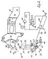
- a locking device usable for this purpose other Structure relates to the invention, which is based below of Figures 3ff is explained in more detail, wherein this locking device is designated with a total of 30 and only here with regard to those essential for the understanding of the invention Parts is shown.
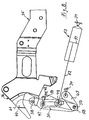
- locking member 31, guide gear 32 and actuator 33 are the support element the against each other via the locking device 30 locking elements assigned, the support element, analog to the design according to Figures 1 and 2 by the schematic indicated vehicle body 34 is formed.
- Figure 3 shows for the locking member 31 - corresponding to the locking member 13 in Figures 1 and 2 - and the counter member 36 - corresponding to counter-member 12 in Figure 1 and 2 -in their position in relation to each other is a position such as when pivoting of the support frame 35 in its closed position shortly before reaching the Locking position is given, the further movement of the Counter member 36 in the direction of the locking position for the Support frame 35 is illustrated by the arrow 37.
- the locking member 31 and the counter member 36 are in the embodiment each assigned a coupling member, and it is this coupling member on the part of the locking member 31 through a coupling pin 38 is formed, and on the part of the counter member 36 by a coupling mouth 39.
- the coupling mouth 39 has one to the jaw pin 38 extending jaw plane and forms to the coupling pin 38 a catch beak, which, based on the direction of arrow 37, an upper catching flank 40 and one has lower latching flank 41, the catching flank 40 in one in the opposite direction to the throat 42 of the coupling mouth 39 itself extending nose 43 which extends in the direction of extension of the Ratchet edge 41 extends beyond this.
- the locking member 31 is designed as a lever that over the guide gear 32 is guided.
- the latter is as a handlebar gearbox formed and includes handlebars 44 and 45 through a coupling 46 are connected and their remote from the coupling 46 base articulation points are fixed and with 47 and 48 are designated.
- the coupling-side articulation points of the Handlebars 44 and 45 are designated 49 and 50.
- a lever designed locking member 31 is with the guide gear connected at its pivot points 47 and 50
- the base Associated and fixed articulation point 47 the guide point a positive-locking sliding coupling, which forms the locking member 31 assigned, has a guide link 51, which extends in the longitudinal direction of the locking member 31 and in their direction of extension with the connecting straight line coincides between the coupling pin 38 and the articulation point 50, in which the coupling 46 is connected to the handlebar 45.
- Actuating cylinder 53 which in the exemplary embodiment is a hydraulic cylinder is formed and the piston rod side, as in Figure 3 indicated, via a volume-compensating pressure accumulator 54 uncontrolled connected to the pressure side of the pump 55 is.
- the connection to the hydraulic circuit is made in the opposite direction for example via a 3/2-way valve 56.
- the different Size of the effective surfaces of the piston 57 on both sides makes it possible to set the actuator cylinder 53 towards the piston rod 52 despite permanent loading of this piston side to adjust if a corresponding one via the directional valve 56 Activation takes place.
- the actuating cylinder 53 is like shown, on the piston rod side, i.e. biased in the direction of entry.
- the pulling force exerted by the piston rod 52 is intercepted via the guide gear 32 and in the articulation points 47 and 48 supported against the vehicle body 34 because the gear 32 is blocked.
- This is achieved in the exemplary embodiment in that in the piston rod side Articulation point 49 on the coupling 46 and at articulation point 50 with the Coupling 46 connected link 45 to coupling 46 in at least extended, preferably overstretched position, namely blocking support against the other handlebar 44.
- This support is in the embodiment by a handlebar 45th assigned nose 58 reached, which is against a formation 59th of the handlebar 44 supports.
- a corresponding one Secure the locking member 31 in position 3 despite the corresponding tensile load on the Ensure actuator 33 when the end position shown only an almost extended position of coupling 46 and handlebar 45 corresponds, with resilient support the same in the direction of their overstretched position.
- Such Resilient support can, for example, which is not shown here done by a traversable detent spring, especially in the position shown because of the guide gear 32 given leverage positions and leverage ratios bad gear ratio for the part on the part of the actuating cylinder 53 traction is exerted.
- Figure 4 shows in this regard the initiation of the pivoting process when approaching of the counter element 35 related to the locking member 31 on Figures 1 and 2 of the support frame 8 on the one in Figure 1 Shown closed position
- Figure 5 shows an intermediate position in which the blocking position is released and the coupling pin 38 of the Locking member 31 on the one hand over the nose 43 of the counter member 36 pressed and on the other hand over the locking member 31 under the influence of the tensile force of the actuator 33 is further introduced into the coupling mouth 39.
- Figure 6 further shows that by further running in of the coupling pin 38 in the coupling mouth 39, now alone due to the pivoting movement of the locking member 31 its guidance via the guide gear 32, the coupling pin 38 runs up against the locking flank 41 and thus in the further Swivel path the counter member 36 and the counter element carrying this 35 takes along in the closing direction.
- Figures 6 and 7 show that through the coupling 46 and the handlebar 44 formed support triangle for the articulated in the pivot point 49 Piston rod 52 progressively, so that there is an improved transmission ratio results, this effect still thereby is reinforced that the initiated via the guide gear 32 Actuating force on the locking member 31 also under one increasingly favorable leverage ratio takes effect.
- the locking position is reached when the handlebar 44 and the coupling 46 at least almost reaches an extended position have, and it will be the locking position shown in FIG 8 secured in a preferred manner according to the invention in that Handlebar 44 and coupling 46 reach an overstretched position is secured against attacks.
- the relevant stop is in figure 8 with 62, fixed to the structure and preferably the handlebar 44 assigned in such a way that it is in the range of Formation 59 interacts.
- the formation 49 is based on the illustrated embodiment through the apex area the handlebar 44 is formed in the case of a triangular configuration, where the base of the triangle is through the connecting straight line the pivot points 47 and 49 is formed.
- the guide gear 32 designed as a steering gear and forms a four-bar linkage, in which the links 44, 45 have essentially the same length and the length of the coupling 46 approximately the length of the link 44, 45 corresponds, is preferably somewhat larger than this.
- the length the base, that is the distance between the articulation points 47 and 48, is in the order of 1.5 times the handlebar length.
- an actuator 33 is a hydraulic one Drive shown, others are also within the scope of the invention Forms of drive, for example mechanically via a Bowden cable or electrically possible.
- the locking device in reverse the locking device also can serve the counter member from its locking position raise the appropriate position to a slightly open position, and so can help to prevent any occurring when opening To overcome breakaway forces or a weaker interpretation of a required for further opening of the counter member Enable actuator.
- flank surface 63 of the catching flank 40 is via the guide gear 32 determined movement path of the coupling pin 38 at an angle on the order of about 45 to 60 Degree is to sufficient adjustment in the direction of the Throat 42 of the coupling mouth 39 with acceptable frictional forces to achieve because despite the intended and inventive the small, space-saving design also achieved a sufficient level Overlap between the coupling pin 38 and the catching flank 40 must be given to compensate for larger tolerances to be able to and secure detection on the one hand and a ensure secure locking on the other hand.
- the locking member 31 is also appropriate to the locking member 31 as a double-edged Form lever, between which the counter member 36 with one-edged Support flank 40 and locking flank 41 engages.
Landscapes
- Engineering & Computer Science (AREA)
- Mechanical Engineering (AREA)
- Lock And Its Accessories (AREA)
- Harvester Elements (AREA)
- Accommodation For Nursing Or Treatment Tables (AREA)
- Prostheses (AREA)
- Jib Cranes (AREA)
Description
- Figur 1
- stark schematisiert, in Seitenansicht den Rückteil eines Kraftfahrzeuges mit Klappverdeck und einem Kofferraumdeckel, unterhalb dessen zumindest teilweise auch der Ablagekasten für das in seine Öffnungslage verbrachte Klappverdeck liegt, und zwar bei geschlossenem Kofferraumdeckel,
- Figur 2
- eine der Figur 1 entsprechende Darstellung bei den Ablagekasten freigebender Schwenklage des Kofferraumdeckels, in der dieser über einen zugeordneten Tragrahmen - und nach Lösen der diesem zugeordneten, vorderen Verriegelungsvorrichtung - nach hinten oben verschwenkt ist,
- Figur 3
- in stark schematisierter Darstellung die wesentlichen Elemente einer für diesen Zweck geeigneten, erfindungsgemäßen Verriegelungsvorrichtung in einer Lage, in der der Tragrahmen in die der Schliesslage des Kofferraumdeckels entsprechende Lage zurückgeführt ist, kurz bevor der Verriegelungsvorgang eingeleitet wird,
- Figur 4
- eine der Figur 3 entsprechende Darstellung in dem Punkt der Annäherungsphase, in dem das karosserieseitige Verriegelungsglied über das dem Tragrahmen zugeordnete Gegenglied tangiert wird,
- Figur 5
- eine Stellung der Verriegelungsvorrichtung in der Annäherung an die Verriegelungsposition, in der das karosserieseitige Verriegelungsglied über das Gegenglied aus einer als Sperrstellung dienenden Bereitschaftsstellung (Figur 4) soweit in Richtung auf die Verriegelungsstellung verschwenkt ist, dass die Sperrstellung aufgehoben ist und eine weitere Verschwenkung über den Stellantrieb möglich ist,
- Figur 6
- eine weitere Stellung im Verriegelungsablauf, wobei die zunächst vom Gegenglied auf das Verriegelungsglied ausgeübte Antriebsfunktion - Überführung von der eine Sperrstellung bildenden Bereitschaftsstellung in eine Freigabestellung - auf den Stellantrieb übergegangen ist und das Verriegelungsglied über den Stellantrieb in eine Mitnahmelage für das Gegenglied verschwenkt ist,
- Figur 7
- eine nächste Stufe im Verriegelungsablauf, in der das Verriegelungsglied das Gegenglied vollständig oder nahezu vollständig in die Verriegelungsstellung eingeschwenkt hat, und
- Figur 8
- die Endstellung des Verriegelungsgliedes in der Verriegelungsposition der über die Verriegelungsvorrichtung zu verbindenden Elemente, hier des Tragrahmens und des Fahrzeugaufbaues, bei formschlüssiger Sicherung des Verriegelungsgliedes in der Verriegelungsstellung.
Claims (36)
- Vorrichtung zur Verriegelung zweier relativ zueinander verstellbarer, zwangsgeführter Elemente in einer Verriegelungsposition, in der die Elemente aneinander angrenzend verbunden sind, insbesondere zur Verriegelung eines eine Fahrzeugöffnung abdeckenden Teiles gegenüber dem Fahrzeugaufbau, bei der das eine Element ein Tragelement (34) für ein Führungsgetriebe (32) mit einem Verriegelungsglied (31) bildet, bei der das andere Element als Gegenelement (35) mit einem Gegenglied (36) versehen ist, bei der das Verriegelungsglied (31) über das Führungsgetriebe (32) aus einer Bereitschaftsstellung zur Erfassung des Gegengliedes (36) in eine der Verriegelungsposition der Elemente (34, 35) entsprechende Verriegelungsstellung für das erfasste Gegenglied (36) überführbar ist und bei der das Führungsgetriebe (32) mit einem Stellantrieb (32) verbunden ist, wobei das Verriegelungsglied (31) in seiner Bereitschaftsstellung gegen Verstellung durch den Stellantrieb (32) in Richtung auf seine Verriegelungsstellung gesperrt und aus dieser gegen Verstellung durch den Verstellantrieb (33) gesperrten Lage durch Beaufschlagung über das Gegenelement (35) zu lösen ist,
dadurch gekennzeichnet, dass als Führungsgetriebe (32) ein Lenkergetriebe vorgesehen ist, das ein Gelenkviereck mit Anlenkpunkten (47 - 50) bildet, das eine der Bereitschaftsstellung und eine der Verriegelungsstellung entsprechende Endstellung aufweist. - Vorrichtung nach Anspruch 1,
dadurch gekennzeichnet, dass das Verriegelungsglied (31) über das dem Gegenelement (35) zugeordnete Gegenglied (36) in seine die Verstellung über den Stellantrieb (33) in Richtung auf die Verriegelungsstellung freigebende Lage zu überführen ist. - Vorrichtung nach Anspruch 1,
dadurch gekennzeichnet, dass die Bereitschaftsstellung als Sperrlage anschlaggesichert ist. - Vorrichtung nach Anspruch 1,
dadurch gekennzeichnet, dass die Bereitschaftsstellung als Sperrlage federgesichert ist. - Vorrichtung nach Anspruch 1,
dadurch gekennzeichnet, dass das Lenkergetriebe (32) eine Ausbildung aufweist, bei der, bezogen auf eine vorgegebene Stellkraft des Stellantriebes (33), das Verriegelungsglied (31) im Bereich seiner Verriegelungsstellung maximal belastet ist. - Vorrichtung nach Anspruch 1,
dadurch gekennzeichnet, dass von den Basis und Koppel (46) des Gelenkviereckes verbindenden Lenkern (44, 45) der eine Lenker (45) in der der Bereitschaftsstellung entsprechenden Stellung und der andere Lenker (44) in der der Verriegelungsstellung entsprechenden Endstellung zur Koppel (46) etwa in Flucht liegt. - Vorrichtung nach einem der Ansprüche 5 oder 6,
dadurch gekennzeichnet, dass das Verriegelungsglied (31) im Anlenkpunkt (50) eines Lenkers (45) an der Koppel (46) mit dem Lenkergetriebe (32) verbunden ist. - Vorrichtung nach einem der Ansprüche 5 bis 7,
dadurch gekennzeichnet, dass der Stellantrieb (33) im Anlenkpunkt (49) eines Lenkers (44) an der Koppel (46) mit dem Lenkergetriebe (32) verbunden ist. - Vorrichtung nach einem der Ansprüche 5 bis 8,
dadurch gekennzeichnet, dass der Stellantrieb (33) und das Verriegelungsglied (31) in jeweils einem anderen der beiden Anlenkpunkte (49, 50) der Koppel (46) an den Lenkern (44, 45) mit dem Lenkergetriebe (32) verbunden ist. - Vorrichtung nach einem der Ansprüche 5 bis 9,
dadurch gekennzeichnet, dass das Verriegelungsglied (31) durch eine Formschluss-Gleitkopplung in einem zur Basis des Gelenkviereckes lagefesten, durch den Anlenkpunkt (47) gebildeten Führungspunkt gelagert ist. - Vorrichtung nach Anspruch 10,
dadurch gekennzeichnet, dass der Führungspunkt der Formschluss-Gleitkopplung durch einen der basisseitigen Anlenkpunkte (47) des Lenkergetriebes (32) gebildet ist. - Vorrichtung nach Anspruch 10 oder 11,
dadurch gekennzeichnet, dass der basisseitige, den Führungspunkt der Formschluss-Gleitkopplung bildende Anlenkpunkt (47) dem Lenker (44) zugeordnet ist, in dessen Anlenkpunkt (49) zur Koppel (46) der Stellantrieb (33) angreift. - Vorrichtung nach Anspruch 2,
dadurch gekennzeichnet, dass dem Verriegelungsglied (31) und dem Gegenglied (36) jeweils ein Kupplungsglied (38, 39) zugeordnet ist und dass von den Kupplungsgliedern das eine als Kupplungszapfen (38) und das andere als Kupplungsmaul (39) ausgebildet ist. - Vorrichtung nach einem der Ansprüche 1 bis 13,
dadurch gekennzeichnet, dass das Verriegelungsglied (31) in seiner Bereitschaftsstellung eine Lage einnimmt, in der sein getriebeseitiger Anlenkpunkt (50), sein durch den Anlenkpunkt (47) gebildeter Führungspunkt und sein durch einen Kupplungszapfen (38) gebildetes Kupplungsglied in etwa auf einer Verbindungsgeraden liegen. - Vorrichtung nach Anspruch 14,
dadurch gekennzeichnet, dass die Erstreckungsrichtung der Verbindungsgeraden in der Bereitschaftsstellung etwa der Erstreckungsrichtung der Basis des Gelenkviereckes entspricht. - Vorrichtung nach Anspruch 14 und 15,
dadurch gekennzeichnet, dass, bezogen auf die Bereitschaftsstellung, der im durch den Anlenkpunkt (47) gebildeten Führungspunkt angelenkte Lenker (44) und die Koppel (46) zueinander spitzwinklig liegen. - Vorrichtung nach einem der Ansprüche 15 oder 16,
dadurch gekennzeichnet, dass, bezogen auf die Bereitschaftsstellung, die Koppel (46) und der im Anlenkpunkt (50) des Verriegelungsgliedes (31) anschließende Lenker (45) etwa gleiche Erstreckungsrichtung aufweisen. - Vorrichtung nach Anspruch 17,
dadurch gekennzeichnet, dass die Koppel (46) und der im Anlenkpunkt (50) des Verriegelungsgliedes (31) anschließende Lenker (45) eine in Richtung auf den Führungspunkt überstreckte Lage einnehmen. - Vorrichtung nach Anspruch 17,
dadurch gekennzeichnet, dass die Koppel (46) und der im Anlenkpunkt (50) des Verriegelungsgliedes (31) anschließende Lenker (45) eine gestreckte Lage einnehmen. - Vorrichtung nach einem der Ansprüche 17 bis 19,
dadurch gekennzeichnet, dass, bezogen auf die Bereitschaftsstellung, die Koppel (46) und/oder der im Anlenkpunkt (50) des Verriegelungsgliedes (31) anschließende Lenker (45) in Richtung auf den Führungspunkt federbelastet sind. - Vorrichtung nach einem der Ansprüche 17 bis 20,
dadurch gekennzeichnet, dass, bezogen auf die Bereitschaftsstellung, die Koppel (46) und/oder der im Anlenkpunkt (50) des Verriegelungsgliedes (31) anschließende Lenker (45) im Schwenkweg auf den Führungspunkt anschlagbegrenzt sind. - Vorrichtung nach einem der Ansprüche 12 bis 21,
dadurch gekennzeichnet, dass die Formschluss-Gleitkopplung eine Führungskulisse (51) umfasst, die sich in Erstreckungsrichtung der Verbindungsgeraden des Anlenkpunktes (50) zwischen Verriegelungsglied (31) und Koppel (46) und dem dem Verriegelungsglied (31) zugeordneten, durch den Kupplungszapfen (38) gebildetes Kupplungsglied erstreckt. - Vorrichtung nach einem der Ansprüche 1 bis 22,
dadurch gekennzeichnet, dass die Lenker (44, 45) etwa gleiche Länge aufweisen. - Vorrichtung nach einem der Ansprüche 1 bis 23,
dadurch gekennzeichnet, dass die Koppel (46) länger als ein Lenker (44 bzw. 45) ist. - Vorrichtung nach einem der Ansprüche 1 bis 24,
dadurch gekennzeichnet, dass, bezogen auf die Bereitschaftsstellung, die Kraftwirkungslinie des Stellantriebes (33) mit dem der Winkelhalbierenden des von Koppel (46) und im Führungspunkt des Verriegelungsgliedes (31) angelenktem Lenker (44) eingeschlossenen Winkels zusammenfällt. - Vorrichtung nach einem der Ansprüche 1 bis 25,
dadurch gekennzeichnet, dass in der der Verriegelungsposition der Elemente (34, 35) entsprechenden Verriegelungsstellung die Koppel (46) und der im Führungspunkt angelenkte Lenker (44) etwa eine gestreckte Lage einnehmen. - Vorrichtung nach einem der Ansprüche 1 bis 26,
dadurch gekennzeichnet, dass in der der Verriegelungsposition der Elemente (34, 35) entsprechenden Verriegelungsstellung die Koppel (46) und der im Führungspunkt des Verriegelungsgliedes (31) angelenkte Lenker (44) eine in Richtung auf die Basis des Gelenkviereckes überstreckte Lage einnehmen. - Vorrichtung nach Anspruch 26 oder 27,
dadurch gekennzeichnet, dass in der der Verriegelungsposition der Elemente (34, 35) entsprechenden Verriegelungsstellung die Koppel (46) und der im Führungspunkt des Verriegelungsgliedes (31) angelenkte Lenker (44) eine zur Wirkungslinie der Stellkraft des Stellantriebes (33) etwa senkrechte Erstreckung aufweisen. - Vorrichtung nach einem der Ansprüche 1 bis 28,
dadurch gekennzeichnet, dass die Länge der Führungskulisse (51) etwa der Länge der Koppel (46) entspricht. - Vorrichtung mindestens nach Anspruch 13,
dadurch gekennzeichnet, dass das Verriegelungsglied (31) als Kupplungsglied einen Kupplungszapfen (38) trägt. - Vorrichtung mindestens nach Anspruch 13,
dadurch gekennzeichnet, dass das Gegenglied (36) als Kupplungsglied ein Kupplungsmaul (39) aufweist. - Vorrichtung nach Anspruch 31,
dadurch gekennzeichnet, dass das Kupplungsmaul (39) sich in Schwenkrichtung des Verriegelungsgliedes (31) erstreckt. - Vorrichtung nach Anspruch 31 oder 32,
dadurch gekennzeichnet, dass das Kupplungsmaul (39) bezogen auf den Kupplungszapfen (38) eine diesen in der Verriegelungsstellung übergreifende Fangflanke (40) und eine diesen untergreifende Rastflanke (41) aufweist. - Vorrichtung nach Anspruch 33,
dadurch gekennzeichnet, dass die Fangflanke (40) einer in Gegenrichtung zum Rachen (42) des Kupplungsmaules (39) über die Rastflanke (41) hinausragenden Nase (43) zugeordnet ist. - Vorrichtung nach einem der Ansprüche 31 bis 34,
dadurch gekennzeichnet, dass sich Verriegelungsglied (31) und Rastmaul (39) etwa senkrecht zueinander erstrecken. - Vorrichtung mindestens nach Anspruch 1,
dadurch gekennzeichnet, dass der Stellantrieb (33) in Richtung auf die Verriegelungsstellung vorgespannt ist.
Applications Claiming Priority (2)
| Application Number | Priority Date | Filing Date | Title |
|---|---|---|---|
| DE1999160012 DE19960012C1 (de) | 1999-12-13 | 1999-12-13 | Vorrichtung zur Verriegelung zweier relativ zueineander verstellbarer, zwangsgeführter Elemente |
| DE19960012 | 1999-12-13 |
Publications (3)
| Publication Number | Publication Date |
|---|---|
| EP1108582A2 EP1108582A2 (de) | 2001-06-20 |
| EP1108582A3 EP1108582A3 (de) | 2003-03-19 |
| EP1108582B1 true EP1108582B1 (de) | 2004-03-03 |
Family
ID=7932444
Family Applications (1)
| Application Number | Title | Priority Date | Filing Date |
|---|---|---|---|
| EP00126760A Expired - Lifetime EP1108582B1 (de) | 1999-12-13 | 2000-12-06 | Vorrichtung zur Verriegelung zweier relativ zueinander verstellbarer, zwangsgeführter Elemente |
Country Status (3)
| Country | Link |
|---|---|
| US (1) | US6572157B2 (de) |
| EP (1) | EP1108582B1 (de) |
| DE (2) | DE19960012C1 (de) |
Families Citing this family (15)
| Publication number | Priority date | Publication date | Assignee | Title |
|---|---|---|---|---|
| NL1018035C2 (nl) | 2001-05-10 | 2002-11-12 | Actuant Corp | Hydraulische bedieningsinrichting voor een afdekking met bijbehorende grendel. |
| US6799788B2 (en) * | 2002-04-08 | 2004-10-05 | Ssr Roofing Systems, Llc | Decklid mechanism for vehicle with retractable top |
| US6899368B2 (en) * | 2002-05-23 | 2005-05-31 | Wilhelm Karmann Gmbh | Decklid mechanism for vehicle with retractable top |
| DE10247725B4 (de) * | 2002-10-12 | 2006-08-24 | Wilhelm Karmann Gmbh | Cabriolet-Fahrzeug mit versenkbarem Verdeck |
| NL1022048C2 (nl) * | 2002-12-02 | 2004-06-03 | Mps Holding B V | Drukmodule alsmede een drukmachine voorzien van een dergelijke drukmodule. |
| FR2846604B1 (fr) * | 2003-07-02 | 2012-08-03 | France Design | Capot de coffre arriere pour un vehicule decouvrable a toit repliable |
| DE10353515B3 (de) * | 2003-11-14 | 2005-04-14 | Cts Fahrzeug-Dachsysteme Gmbh | Traggestell mit einem Tragrahmen für einen Heckdeckel eines Personenkraftwagens |
| DE102004033870A1 (de) * | 2004-07-13 | 2006-02-09 | Wilhelm Karmann Gmbh | Cabriolet-Fahrzeug |
| DE102004056657B3 (de) * | 2004-11-23 | 2006-05-24 | Cts Fahrzeug-Dachsysteme Gmbh | Antriebsanordnung für ein Fahrzeugteil |
| DE102005034725A1 (de) * | 2005-07-21 | 2007-01-25 | Wilhelm Karmann Gmbh | Cabriolet-Fahrzeug mit einem im rückwärtigen Fahrzeugbereich ablegbaren Dach |
| US7762607B2 (en) * | 2006-12-21 | 2010-07-27 | Wilhelm Karmann Gmbh | Overcenter linkage mechanism for a decklid of an automotive vehicle |
| JP5177536B2 (ja) * | 2008-09-25 | 2013-04-03 | アイシン精機株式会社 | オープンルーフ開閉装置 |
| US7819459B2 (en) * | 2009-02-11 | 2010-10-26 | Valmet Automotive Oy | Convertible vehicle |
| CN107675965A (zh) * | 2017-10-31 | 2018-02-09 | 无锡瑞林控制软件有限公司 | 可调行程的拉丝固定结构 |
| US11680430B2 (en) * | 2019-02-20 | 2023-06-20 | Brose Schließsysteme GmbH & Co. Kommanditgesellschaft, Wuppertal | Linear cinching spindle |
Family Cites Families (11)
| Publication number | Priority date | Publication date | Assignee | Title |
|---|---|---|---|---|
| DE1505721B2 (de) * | 1966-04-16 | 1976-06-24 | Daimler-Benz Ag, 7000 Stuttgart | Vorrichtung zur verriegelung eines kraftfahrzeug-klappverdecks |
| DE2327487C2 (de) | 1973-05-30 | 1975-04-30 | Daimler-Benz Ag, 7000 Stuttgart | Schließ- und Verriegelungseinrichtung für einen Verdeckkastendeckel eines Pesonenkraftwagens |
| US4886307A (en) | 1987-04-01 | 1989-12-12 | Ewald Witte & Co. | Lock, particularly for trunk or engine compartments of automotive vehicles, doors or the like |
| DE3743282A1 (de) * | 1987-12-19 | 1989-07-06 | Bayerische Motoren Werke Ag | Verriegelungseinrichtung mit verstellantrieb |
| DE9007595U1 (de) | 1990-12-22 | 1993-03-04 | Design + Technik GmbH Entwicklung und Konstruktion von Industrieaufträgen, 2000 Hamburg | Vorrichtung zum Niederholen des freien Endes eines Fahrzeugverdecks o.dgl. |
| DE4111646C2 (de) * | 1991-04-10 | 1994-12-08 | Bayerische Motoren Werke Ag | Verriegelungseinrichtung, insbesondere für ein Cabrio-Faltverdeck |
| DE4322689C2 (de) | 1992-07-08 | 1999-07-08 | Ohi Seisakusho Co Ltd | Verriegelungsvorrichtung |
| NL9302107A (nl) * | 1993-12-03 | 1995-07-03 | Applied Power Inc | Inrichting voor het vastzetten van een dak van een voertuig, in het bijzonder een cabriolet-vouwdak, en voertuig voorzien van een dergelijke inrichting. |
| US5620226A (en) | 1995-12-07 | 1997-04-15 | Dura Convertible Systems, Inc. | Simplified automated top operator |
| FI107718B (fi) | 1998-02-27 | 2001-09-28 | Valmet Automotive Oy | Ajoneuvo ja avattava katto ajoneuvoa varten |
| US6290281B1 (en) | 1999-05-26 | 2001-09-18 | Asc Incorporated | Power latch for an automotive vehicle convertible roof system |
-
1999
- 1999-12-13 DE DE1999160012 patent/DE19960012C1/de not_active Expired - Lifetime
-
2000
- 2000-12-06 DE DE50005503T patent/DE50005503D1/de not_active Expired - Lifetime
- 2000-12-06 EP EP00126760A patent/EP1108582B1/de not_active Expired - Lifetime
- 2000-12-13 US US09/734,594 patent/US6572157B2/en not_active Expired - Fee Related
Also Published As
| Publication number | Publication date |
|---|---|
| US20010042998A1 (en) | 2001-11-22 |
| DE50005503D1 (de) | 2004-04-08 |
| US6572157B2 (en) | 2003-06-03 |
| DE19960012C1 (de) | 2001-02-15 |
| EP1108582A3 (de) | 2003-03-19 |
| EP1108582A2 (de) | 2001-06-20 |
Similar Documents
| Publication | Publication Date | Title |
|---|---|---|
| EP1197368B1 (de) | Mehrteilige Abdeckung für Fahrzeuge | |
| EP0747553B1 (de) | Kraftfahrzeug-Türgriff | |
| EP1989082B1 (de) | Karosserie für ein kraftfahrzeug | |
| DE19944615C2 (de) | Schloß für ein verschwenkbares Kraftfahrzeugverdeck | |
| DE102016011162A1 (de) | Verriegelungsvorrichtung für eine Fahrzeugtür und Verfahren | |
| EP0826539A1 (de) | Bewegliche Dachkonstruktion für einen offenen Personenkraftwagen | |
| DE19960012C1 (de) | Vorrichtung zur Verriegelung zweier relativ zueineander verstellbarer, zwangsgeführter Elemente | |
| DE10038530B4 (de) | Cabriolet-Fahrzeug mit einem unter einem Deckelteil ablegbaren Dach | |
| DE102005043508B4 (de) | Dach für Fahrzeuge mit offenem Aufbau | |
| DE102009018188B4 (de) | Vorrichtung zum automatischen Schließen einer Fahrzeugtür | |
| DE19801853C1 (de) | Antriebseinrichtung für einen Verdeckkastendeckel | |
| DE19912893C2 (de) | Cabrio-Fahrzeug mit einem Verdeck | |
| EP1831042B1 (de) | Kraftfahrzeug mit einem beweglichen deckelteil der karosserie | |
| EP1034979B1 (de) | Hutablage für Fahrzeuge mit abklappbarem Verdeck | |
| DE102007060486B4 (de) | Abdeckvorrichtung für ein Fahrzeug | |
| EP1414660B1 (de) | Verdeckkasten zur aufnahme eines verstellbaren fahrzeugverdecks | |
| DE10358960B3 (de) | Verstellbares Fahrzeugdach mit einer Verriegelungseinrichtung zum Verriegeln mindestens eines Dachteils | |
| DE102004059793B3 (de) | Verstellbares Deckelelement in einem Fahrzeug, insbesondere in einem Cabriolet-Fahrzeug und verstellbares Fahrzeugdach | |
| DE10156011C2 (de) | Verstellbares Deckelelement in einem Fahrzeug | |
| DE102007006518B4 (de) | Anlenkung für einen Heckdeckel | |
| EP0400376A2 (de) | Verstelleinrichtung an einem Faltverdeck eines Kraftfahrzeugs | |
| DE19513249C1 (de) | Kraftfahrzeug-Türgriff | |
| DE102006043817A1 (de) | Bewegungsmechanismus für eine Stauraumklappe eines Omnibusses | |
| DE10353515B3 (de) | Traggestell mit einem Tragrahmen für einen Heckdeckel eines Personenkraftwagens | |
| DE102011119500B4 (de) | Cabriolet-Fahrzeug mit einem verstellbaren Fahrzeugdach |
Legal Events
| Date | Code | Title | Description |
|---|---|---|---|
| PUAI | Public reference made under article 153(3) epc to a published international application that has entered the european phase |
Free format text: ORIGINAL CODE: 0009012 |
|
| AK | Designated contracting states |
Kind code of ref document: A2 Designated state(s): AT BE CH CY DE DK ES FI FR GB GR IE IT LI LU MC NL PT SE TR |
|
| AX | Request for extension of the european patent |
Free format text: AL;LT;LV;MK;RO;SI |
|
| PUAL | Search report despatched |
Free format text: ORIGINAL CODE: 0009013 |
|
| AK | Designated contracting states |
Kind code of ref document: A3 Designated state(s): AT BE CH CY DE DK ES FI FR GB GR IE IT LI LU MC NL PT SE TR |
|
| AX | Request for extension of the european patent |
Extension state: AL LT LV MK RO SI |
|
| RIC1 | Information provided on ipc code assigned before grant |
Ipc: 7B 60J 7/20 B Ipc: 7E 05B 65/19 B Ipc: 7B 60J 7/185 A |
|
| 17P | Request for examination filed |
Effective date: 20030703 |
|
| GRAP | Despatch of communication of intention to grant a patent |
Free format text: ORIGINAL CODE: EPIDOSNIGR1 |
|
| AKX | Designation fees paid |
Designated state(s): DE FR |
|
| GRAS | Grant fee paid |
Free format text: ORIGINAL CODE: EPIDOSNIGR3 |
|
| GRAA | (expected) grant |
Free format text: ORIGINAL CODE: 0009210 |
|
| AK | Designated contracting states |
Kind code of ref document: B1 Designated state(s): DE FR |
|
| RIN1 | Information on inventor provided before grant (corrected) |
Inventor name: OBENDIEK, KLAUS Inventor name: KAUTE, MARKUS Inventor name: ZIPPERLE, SIGFRIED Inventor name: SCHULER, ECKART |
|
| REG | Reference to a national code |
Ref country code: IE Ref legal event code: FG4D Free format text: GERMAN |
|
| REF | Corresponds to: |
Ref document number: 50005503 Country of ref document: DE Date of ref document: 20040408 Kind code of ref document: P |
|
| REG | Reference to a national code |
Ref country code: IE Ref legal event code: FD4D |
|
| ET | Fr: translation filed | ||
| PLBE | No opposition filed within time limit |
Free format text: ORIGINAL CODE: 0009261 |
|
| STAA | Information on the status of an ep patent application or granted ep patent |
Free format text: STATUS: NO OPPOSITION FILED WITHIN TIME LIMIT |
|
| 26N | No opposition filed |
Effective date: 20041206 |
|
| PGFP | Annual fee paid to national office [announced via postgrant information from national office to epo] |
Ref country code: FR Payment date: 20110107 Year of fee payment: 11 |
|
| PGFP | Annual fee paid to national office [announced via postgrant information from national office to epo] |
Ref country code: DE Payment date: 20110125 Year of fee payment: 11 |
|
| REG | Reference to a national code |
Ref country code: FR Ref legal event code: ST Effective date: 20120831 |
|
| REG | Reference to a national code |
Ref country code: DE Ref legal event code: R119 Ref document number: 50005503 Country of ref document: DE Effective date: 20120703 |
|
| PG25 | Lapsed in a contracting state [announced via postgrant information from national office to epo] |
Ref country code: DE Free format text: LAPSE BECAUSE OF NON-PAYMENT OF DUE FEES Effective date: 20120703 |
|
| PG25 | Lapsed in a contracting state [announced via postgrant information from national office to epo] |
Ref country code: FR Free format text: LAPSE BECAUSE OF NON-PAYMENT OF DUE FEES Effective date: 20120102 |