EP1108625B1 - Module de coussin gonflable fixé par encliquetage, avec logement en forme de moyeu - Google Patents
Module de coussin gonflable fixé par encliquetage, avec logement en forme de moyeu Download PDFInfo
- Publication number
- EP1108625B1 EP1108625B1 EP00126573A EP00126573A EP1108625B1 EP 1108625 B1 EP1108625 B1 EP 1108625B1 EP 00126573 A EP00126573 A EP 00126573A EP 00126573 A EP00126573 A EP 00126573A EP 1108625 B1 EP1108625 B1 EP 1108625B1
- Authority
- EP
- European Patent Office
- Prior art keywords
- peripheral wall
- restraint system
- occupant restraint
- vehicle occupant
- gas bag
- Prior art date
- Legal status (The legal status is an assumption and is not a legal conclusion. Google has not performed a legal analysis and makes no representation as to the accuracy of the status listed.)
- Expired - Lifetime
Links
- 230000002093 peripheral effect Effects 0.000 claims description 48
- 239000006260 foam Substances 0.000 claims description 6
- 229920003023 plastic Polymers 0.000 claims description 5
- 239000004033 plastic Substances 0.000 claims description 5
- 239000002184 metal Substances 0.000 claims description 2
- 230000004308 accommodation Effects 0.000 claims 4
- 238000005452 bending Methods 0.000 description 2
- 238000004519 manufacturing process Methods 0.000 description 1
- 238000007493 shaping process Methods 0.000 description 1
Images



Classifications
-
- B—PERFORMING OPERATIONS; TRANSPORTING
- B60—VEHICLES IN GENERAL
- B60R—VEHICLES, VEHICLE FITTINGS, OR VEHICLE PARTS, NOT OTHERWISE PROVIDED FOR
- B60R21/00—Arrangements or fittings on vehicles for protecting or preventing injuries to occupants or pedestrians in case of accidents or other traffic risks
- B60R21/02—Occupant safety arrangements or fittings, e.g. crash pads
- B60R21/16—Inflatable occupant restraints or confinements designed to inflate upon impact or impending impact, e.g. air bags
- B60R21/20—Arrangements for storing inflatable members in their non-use or deflated condition; Arrangement or mounting of air bag modules or components
- B60R21/217—Inflation fluid source retainers, e.g. reaction canisters; Connection of bags, covers, diffusers or inflation fluid sources therewith or together
-
- B—PERFORMING OPERATIONS; TRANSPORTING
- B60—VEHICLES IN GENERAL
- B60R—VEHICLES, VEHICLE FITTINGS, OR VEHICLE PARTS, NOT OTHERWISE PROVIDED FOR
- B60R21/00—Arrangements or fittings on vehicles for protecting or preventing injuries to occupants or pedestrians in case of accidents or other traffic risks
- B60R21/02—Occupant safety arrangements or fittings, e.g. crash pads
- B60R21/16—Inflatable occupant restraints or confinements designed to inflate upon impact or impending impact, e.g. air bags
- B60R21/20—Arrangements for storing inflatable members in their non-use or deflated condition; Arrangement or mounting of air bag modules or components
- B60R21/203—Arrangements for storing inflatable members in their non-use or deflated condition; Arrangement or mounting of air bag modules or components in steering wheels or steering columns
- B60R21/2035—Arrangements for storing inflatable members in their non-use or deflated condition; Arrangement or mounting of air bag modules or components in steering wheels or steering columns using modules containing inflator, bag and cover attachable to the steering wheel as a complete sub-unit
-
- B—PERFORMING OPERATIONS; TRANSPORTING
- B60—VEHICLES IN GENERAL
- B60R—VEHICLES, VEHICLE FITTINGS, OR VEHICLE PARTS, NOT OTHERWISE PROVIDED FOR
- B60R21/00—Arrangements or fittings on vehicles for protecting or preventing injuries to occupants or pedestrians in case of accidents or other traffic risks
- B60R21/02—Occupant safety arrangements or fittings, e.g. crash pads
- B60R21/16—Inflatable occupant restraints or confinements designed to inflate upon impact or impending impact, e.g. air bags
- B60R21/20—Arrangements for storing inflatable members in their non-use or deflated condition; Arrangement or mounting of air bag modules or components
- B60R21/205—Arrangements for storing inflatable members in their non-use or deflated condition; Arrangement or mounting of air bag modules or components in dashboards
-
- B—PERFORMING OPERATIONS; TRANSPORTING
- B60—VEHICLES IN GENERAL
- B60R—VEHICLES, VEHICLE FITTINGS, OR VEHICLE PARTS, NOT OTHERWISE PROVIDED FOR
- B60R21/00—Arrangements or fittings on vehicles for protecting or preventing injuries to occupants or pedestrians in case of accidents or other traffic risks
- B60R21/02—Occupant safety arrangements or fittings, e.g. crash pads
- B60R21/16—Inflatable occupant restraints or confinements designed to inflate upon impact or impending impact, e.g. air bags
- B60R21/20—Arrangements for storing inflatable members in their non-use or deflated condition; Arrangement or mounting of air bag modules or components
- B60R21/207—Arrangements for storing inflatable members in their non-use or deflated condition; Arrangement or mounting of air bag modules or components in vehicle seats
-
- B—PERFORMING OPERATIONS; TRANSPORTING
- B60—VEHICLES IN GENERAL
- B60R—VEHICLES, VEHICLE FITTINGS, OR VEHICLE PARTS, NOT OTHERWISE PROVIDED FOR
- B60R21/00—Arrangements or fittings on vehicles for protecting or preventing injuries to occupants or pedestrians in case of accidents or other traffic risks
- B60R21/02—Occupant safety arrangements or fittings, e.g. crash pads
- B60R21/16—Inflatable occupant restraints or confinements designed to inflate upon impact or impending impact, e.g. air bags
- B60R21/20—Arrangements for storing inflatable members in their non-use or deflated condition; Arrangement or mounting of air bag modules or components
- B60R21/21—Arrangements for storing inflatable members in their non-use or deflated condition; Arrangement or mounting of air bag modules or components in vehicle side panels, e.g. doors
-
- B—PERFORMING OPERATIONS; TRANSPORTING
- B60—VEHICLES IN GENERAL
- B60R—VEHICLES, VEHICLE FITTINGS, OR VEHICLE PARTS, NOT OTHERWISE PROVIDED FOR
- B60R21/00—Arrangements or fittings on vehicles for protecting or preventing injuries to occupants or pedestrians in case of accidents or other traffic risks
- B60R21/02—Occupant safety arrangements or fittings, e.g. crash pads
- B60R21/16—Inflatable occupant restraints or confinements designed to inflate upon impact or impending impact, e.g. air bags
- B60R21/20—Arrangements for storing inflatable members in their non-use or deflated condition; Arrangement or mounting of air bag modules or components
- B60R21/213—Arrangements for storing inflatable members in their non-use or deflated condition; Arrangement or mounting of air bag modules or components in vehicle roof frames or pillars
Definitions
- the invention relates to a vehicle occupant restraint system after the generic term of Claim 1.
- Gas bag modules in steering wheels usually have a plastic cover, the front, which is assigned to the passenger compartment is, form.
- the cup-shaped module covers not screwed with supporting module covers or riveted. Rather, locking connections, the fastening straps have provided, so that after the onset of the gas bag in the Receiving housing, the module cover only on the receiving housing put on and at the same time the locking connection is locked.
- the Unfolding the gas bag ruptures the cover on the front and swings outwards.
- the associated peripheral wall of the cover is thus also bent outward. This could lead to the Detent connection releases.
- This locking plate is on the side bent near the side surface of the module towards the front and supports the peripheral wall of the module cover, which is not so far can bend outward that the locking connection is released.
- the locking plate does not necessarily have to be angled be, there are other embodiments conceivable.
- the invention provides a vehicle occupant restraint system to the locking connection between the two peripheral walls secured in a simpler and more cost-effective manner. This is going through a vehicle occupant restraint system according to claim 1 achieved.
- the invention is therefore not a separate, only for the purpose of securing the latching connection provided sheet more available, but is the space around the gas bag module in the steering wheel designed so that the space defining, anyway provided receiving body the Fuse forms.
- the first peripheral wall is the laterally outer. This ensures that the gas bag in the folded State laterally abut the receiving housing and a can take the largest possible width.
- the module cover are made Plastic and the housing made of sheet metal, of course, the Recording housing can be made of plastic.
- the receiving housing advantageously has laterally in recesses in the first peripheral wall protruding latching hooks, which with the Recesses form the locking connection.
- the latching hooks can also vice versa on the peripheral wall and the recesses in the receiving housing be provided.
- the receiving body widens preferably to the front to the outside, thus allowing a certain bending of the peripheral wall of the module cover to the outside when the front of the module cover is torn open.
- the receiving body is not unfolded Condition of the gas bag already on the outer peripheral wall.
- the Receiving body also serves for the lateral fixation of the gas bag module in the vehicle, so he has a double function in this case.
- a vehicle occupant restraint system which consists of a gas bag module 3 and a receiving body 5.
- the Receiving body 5 is a hub pot, for example, a cup-shaped trained hub of the vehicle steering wheel.
- the receiving body can also a carrier plate in the area of the dashboard on the passenger side, be in the seat, the side door or the roof frame.
- the hubbub must be explained as explained by the invention spärter, not exclusively formed only by the hub of the steering wheel and it does not have to be closed circumferentially, but it must be closed is sufficient that spoke sections, the SpichenumCumung or other already provided parts near the module 3 towards protrude a front side 7 of the module.
- the gas bag module includes the already mentioned front side, a side surface 9 and a back 11th
- the gas bag module further consists of a pot-like module cover 13 with a closed peripheral wall 15, which in the following first Peripheral wall is called.
- the gas bag module is made a preferably inverted cup-shaped receptacle housing 17 Sheet.
- This receiving housing 17 has a rear wall 19 and a Circumferential wall 21, hereinafter called the second peripheral wall, on.
- First and second peripheral wall 15, 21 are in contact with each other and through several Locking connections 23, 25 attached to each other.
- the locking connections are formed so that a sliding of the module cover 7 on the Although housing 17 is possible, but not a peeling the Module cover.
- the side surface 9 is in the upper area by the outside the first peripheral wall 15 and in the lower area through the outside the peripheral wall 21 defined.
- Module cover 7 and receiving housing 17th define a space 27 for accommodating an airbag 29.
- the airbag 29 is only stylized and is in practice at the Peripheral wall 21 and fills almost the entire room 27.
- the rear wall 19 is a gas generator 31 on the receiving housing 17th appropriate.
- a restraint system which is already known. Since when unfolding the gas bag the Module cover 7 tears on the front and swings outward, too the peripheral wall 15 is pressed outwards, as with broken lines is indicated. The peripheral wall 15 could be so far outward be pivoted that the locking connection 23 dissolves. To this, too prevent is a cup-shaped locking plate 33 from below to the Mounted housing. The protruding to the front 7 section of the locking plate is almost at the first peripheral wall 15 and prevents excessive bending of the peripheral wall 15 during deployment of the gas bag.
- the receiving body (hub pot) 5 is shaped so that he close to the peripheral wall 15, which is the laterally outer of the two Circumferential walls 15, 21 forms, runs, so that he partially to her is applied.
- the receiving body 5 thus forms a fuse for the module cover, whose peripheral wall 15 so to speak between the second Peripheral wall 21 and the receiving body 5 is supported.
- the receiving body 5 which is fixed on the vehicle side and forms a vehicle frame part, that vehicle-fixed part on which the gas bag module 3 is locked.
- the receiving body is a cup-shaped hub of the steering wheel with a Floor 51 and a circumferentially closed side wall 53rd
- the two peripheral walls 15, 21 circumferentially not have to be closed, but that also appropriate Sections can perform the functions explained.
- the receiving body 5 is not at the same time the attachment of the gas bag module 3 serve. Rather, the receiving body 5 can also consist of several adjacent Parts to be assembled, with a part for fixing the Airbag module 3 is used and an adjacent part so close to the Circumferential wall 15 is placed so that it can serve as a backup.
- FIGS. 2 and 3 various forms of the Locking connection shown. Both detent connections can of course used in the invention.
- the illustrated in Fig. 2 Locking connection 23 consists of a punched and laterally externally bent hook-shaped extension 41 as part of the peripheral wall 21st and a recess 43 in the peripheral wall 15th
- the locking connection 25 shown in Fig. 3, however, consists of a hook-shaped upper edge portion 45 of the peripheral wall 21 and a corresponding, also in cross-section hook-shaped Recess 47 in the peripheral wall 15, wherein the recess 47 but does not penetrate the peripheral wall 15.
- Fig. 1 is also shown in the right half, that is the receiving body 5 to the front 7 expands and that the peripheral wall 15 at the outwardly flared upper portion of the receiving body 5 is present.
- the receiving body 5 supports during deployment of the Gas bag, the peripheral wall 15 from the side and thus secures the Locking connection 25 or 23.
- the hub pot from the skeleton of the steering wheel formed from the hub, which forms the bottom 51, and the Skeleton of the spokes attached to the hub and the circumference do not form closed side wall 53.
- the side surface 9 lies on the skeleton of the spokes, i.e. on the side wall 53 on.
- Figure 5 corresponds substantially to Figure 4, but the Skeleton 61 of the spokes a foam 63 with a radially inward extending projection 65 as a stop for the outer peripheral wall 15th Has.
- the skeleton lies Spoke outside the cutting plane.
- the skeleton is covered with a foam 63 provided, the hub pot one in the circumferential direction closed shape gives.
- the projection 65, on which the peripheral wall 15th strikes, lies between two spokes.
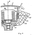
- the bottom 51 of the Hub of the steering wheel and the side wall 53 of a steering wheel cover in the form of a plastic shell attached to the rear of the hub formed the peripheral wall when opening the module.
- a rib 71 secures the peripheral wall 15.
Landscapes
- Engineering & Computer Science (AREA)
- Mechanical Engineering (AREA)
- Air Bags (AREA)
Claims (11)
- Système de retenue de passager de véhicule,
comportant un module de coussin à gaz (3) qui présente
une face antérieure (7), une face latérale (9) et une face postérieure (11) et en outre un couvercle de module (13) en forme de pot, avec une première paroi périphérique (15), et un boítier de réception (17) avec une deuxième paroi périphérique (21),
le couvercle de module (13) et le boítier de réception (17) définissant un espace (27) pour loger un coussin à gaz (29) faisant partie du module (3) et
les première et deuxième parois périphériques (15, 21) étant reliées l'une à l'autre par une liaison à enclenchement (23 ; 25) et au moins une des parois périphériques (15,21) définissant la surface latérale (9),
et comportant un corps de réception (5), fixé côté véhicule, pour le module de coussin à gaz (3), sous forme d'un pot de moyeu d'un volant de direction qui présente un moyeu et des rayons,
le corps de réception (5) étant agencé si près de la face latérale (9) qu'il soutient latéralement celle des deux parois latérales (15, 21) qui est située latéralement à l'extérieur lorsque le module de coussin à gaz (3) s'ouvre, et qu'il assure la liaison à enclenchement,
caractérisé en ce que le pot de moyeu est formé par le moyeu et par les rayons et en ce que celle des parois périphériques qui est située à l'extérieur prend appui sur les rayons lorsque le module de coussin à gaz s'ouvre. - Système de retenue de passager de véhicule selon la revendication 1, caractérisé en ce que la première paroi périphérique (15) est celle qui est située à l'extérieur.
- Système de retenue de passager de véhicule selon la revendication 1 ou 2, caractérisé en ce que le couvercle de module (13) est en matière plastique et le boítier de réception (17) est en tôle.
- Système de retenue de passager de véhicule selon l'une des revendications précédentes, caractérisé en ce que le boítier de réception (17) présente des crochets d'enclenchement (41 ; 45) faisant saillie latéralement dans des évidements (43 ; 47) ménagés dans la première paroi périphérique (15).
- Système de retenue de passager de véhicule selon l'une des revendications précédentes, caractérisé en ce que le corps de réception (5) est en appui sur la paroi périphérique (15) latéralement extérieure, à l'état non déployé du coussin à gaz (29).
- Système de retenue de passager de véhicule selon l'une des revendications précédentes, caractérisé en ce que le corps de réception (5) s'évase vers l'extérieur vers la face antérieure.
- Système de retenue de passager de véhicule selon l'une des revendications précédentes, caractérisé en ce que les rayons présentent un squelette et la paroi périphérique extérieure prend appui sur le squelette des rayons lorsque le module de coussin à gaz s'ouvre.
- Système de retenue de passager de véhicule selon l'une des revendications 1 à 6, caractérisé en ce que les rayons présentent un enrobage de mousse et la paroi périphérique extérieure prend appui sur l'enrobage de mousse lorsque le module de coussin à gaz s'ouvre.
- Système de retenue de passager de véhicule selon la revendication 8, caractérisé en ce que l'enrobage de mousse a une saillie s'étendant vers la paroi périphérique extérieure et servant de butée pour la paroi périphérique extérieure.
- Système de retenue de passager de véhicule selon la revendication 8, caractérisé en ce que l'enrobage de mousse confère au pot de moyeu une configuration fermée en direction périphérique.
- Système de retenue de passager de véhicule selon l'une des revendications précédentes, caractérisé en ce que le corps de réception est une tôle de réception ou une tôle de fixation pour le tableau de bord ou pour un cadre façonné d'un siège de véhicule.
Applications Claiming Priority (2)
| Application Number | Priority Date | Filing Date | Title |
|---|---|---|---|
| DE29921857U DE29921857U1 (de) | 1999-12-13 | 1999-12-13 | Fahrzeuginsassen-Rückhaltesystem |
| DE29921857U | 1999-12-13 |
Publications (3)
| Publication Number | Publication Date |
|---|---|
| EP1108625A2 EP1108625A2 (fr) | 2001-06-20 |
| EP1108625A3 EP1108625A3 (fr) | 2004-01-07 |
| EP1108625B1 true EP1108625B1 (fr) | 2005-10-26 |
Family
ID=8082875
Family Applications (1)
| Application Number | Title | Priority Date | Filing Date |
|---|---|---|---|
| EP00126573A Expired - Lifetime EP1108625B1 (fr) | 1999-12-13 | 2000-12-12 | Module de coussin gonflable fixé par encliquetage, avec logement en forme de moyeu |
Country Status (4)
| Country | Link |
|---|---|
| US (1) | US20010005075A1 (fr) |
| EP (1) | EP1108625B1 (fr) |
| DE (2) | DE29921857U1 (fr) |
| ES (1) | ES2250065T3 (fr) |
Families Citing this family (7)
| Publication number | Priority date | Publication date | Assignee | Title |
|---|---|---|---|---|
| DE10157440A1 (de) * | 2001-11-23 | 2003-06-12 | Breed Automotive Tech | Rasteinrichtung für ein Airbagmodul |
| US6783150B2 (en) * | 2002-09-30 | 2004-08-31 | Trw Vehicle Safety Systems Inc. | Snap together mounting of an air bag module and a vehicle steering wheel |
| US10295898B2 (en) | 2016-06-17 | 2019-05-21 | Moonlite World Inc. | Image projection device |
| US10571793B2 (en) * | 2016-06-17 | 2020-02-25 | Moonlite World Inc. | Image projection device |
| WO2018213501A1 (fr) * | 2017-05-16 | 2018-11-22 | Performance Designed Products Llc | Dispositifs d'entrée utilisateur intelligents, et systèmes et procédés de surveillance de tels dispositifs d'entrée utilisateur intelligents |
| FR3113477B1 (fr) * | 2020-08-18 | 2022-09-16 | Autoliv Dev | Volant de véhicule comprenant un habillage de volant et un module de sécurité |
| US12377808B1 (en) * | 2024-10-16 | 2025-08-05 | Faurecia Interior Systems, Inc. | Vehicle interior panel having an expandable airbag chute |
Family Cites Families (10)
| Publication number | Priority date | Publication date | Assignee | Title |
|---|---|---|---|---|
| US5354093A (en) * | 1993-04-05 | 1994-10-11 | General Motors Corporation | Air bag module having integral cover attachment |
| US5505483A (en) * | 1993-04-28 | 1996-04-09 | Nippondenso Co., Ltd. | Airbag safety module for vehicle |
| US5460400A (en) * | 1994-05-20 | 1995-10-24 | Takata, Inc. | Passenger-side air bag module with improved assembly features |
| GB2290268B (en) * | 1994-06-07 | 1998-02-18 | Autoliv Dev | Improvements in or relating to a safety arrangement |
| DE4430588C2 (de) * | 1994-08-19 | 1999-02-25 | Petri Ag | Gassack (Airbag)-System für Kraftfahrzeuge |
| JPH08295199A (ja) | 1995-03-02 | 1996-11-12 | Nippondenso Co Ltd | エアバッグ装置 |
| JPH09142242A (ja) | 1995-11-27 | 1997-06-03 | Toyoda Gosei Co Ltd | 助手席用エアバッグ装置 |
| DE19730837A1 (de) * | 1997-07-18 | 1999-01-21 | Opel Adam Ag | Elastische Abdeckung für eine Airbag-Einrichtung |
| JPH11268602A (ja) | 1998-03-20 | 1999-10-05 | Toyoda Gosei Co Ltd | エアバッグ装置 |
| DE29816568U1 (de) | 1998-09-15 | 1998-11-05 | TRW Automotive Safety Systems GmbH, 63743 Aschaffenburg | Airbag-Modul für Kraftfahrzeuglenkräder |
-
1999
- 1999-12-13 DE DE29921857U patent/DE29921857U1/de not_active Expired - Lifetime
-
2000
- 2000-12-12 ES ES00126573T patent/ES2250065T3/es not_active Expired - Lifetime
- 2000-12-12 EP EP00126573A patent/EP1108625B1/fr not_active Expired - Lifetime
- 2000-12-12 DE DE50011432T patent/DE50011432D1/de not_active Expired - Fee Related
- 2000-12-13 US US09/735,449 patent/US20010005075A1/en not_active Abandoned
Also Published As
| Publication number | Publication date |
|---|---|
| US20010005075A1 (en) | 2001-06-28 |
| DE50011432D1 (de) | 2005-12-01 |
| EP1108625A2 (fr) | 2001-06-20 |
| ES2250065T3 (es) | 2006-04-16 |
| DE29921857U1 (de) | 2000-04-20 |
| EP1108625A3 (fr) | 2004-01-07 |
Similar Documents
| Publication | Publication Date | Title |
|---|---|---|
| DE69910181T2 (de) | Airbagmodul-mechanismus und verfahren zur montage eines airbags | |
| DE4437773C1 (de) | Instrumententafel mit einem integrierten, aufklappbaren Gassackdeckel | |
| EP0668195B1 (fr) | Couvercle pour un dispositif de retenue par sac gonflable dans un véhicule | |
| EP1288084B1 (fr) | Module de coussin gonflable | |
| DE102011010255B4 (de) | Instrumententafel | |
| DE69208594T2 (de) | Gaskissenschutzvorrichtung | |
| DE69611475T2 (de) | Airbag Abdeckungsanordnung | |
| EP0646499B1 (fr) | Tableau de bord dans une automobile | |
| DE19641641A1 (de) | Airbagmodul mit vereinfachter Kissenbefestigung | |
| EP1087879A1 (fr) | Dispositif de retenue pour panneau d'habillage d'airbag | |
| DE19829755A1 (de) | Airbagvorrichtung für ein Kraftfahrzeug | |
| EP1108625B1 (fr) | Module de coussin gonflable fixé par encliquetage, avec logement en forme de moyeu | |
| DE69619059T2 (de) | Luftsack-Modulgehäuse für Seitenaufprall-Luftsackmodul | |
| EP1324900B1 (fr) | Boitier destine a un coussin gonflable d'un vehicule automobile | |
| DE10241604B4 (de) | Unsichtbare Airbagabdeckung | |
| EP1144226A2 (fr) | Module d'airbag | |
| DE19750945A1 (de) | Seitenaufprallschutzmodul zur Montage an einem Sitz eines Kraftfahrzeugs | |
| DE202005009002U1 (de) | Modulbaugruppe für eine Airbageinrichtung zum Schutz von Insassen eines Kraftfahrzeugs | |
| EP1167123B1 (fr) | Emblème pour couvercle de module de coussin gonflable et module de coussin gonflable | |
| DE69615701T2 (de) | Luftsackmodul | |
| DE10041763B4 (de) | Airbag-Befestigung | |
| EP1426248B1 (fr) | Module de coussin gonflable | |
| EP1452404B1 (fr) | Airbag pour volant de véhicule | |
| EP1251045B1 (fr) | Module de coussin gonflable | |
| EP0983913B1 (fr) | Coussin gonflable et fixation de coussin gonflable |
Legal Events
| Date | Code | Title | Description |
|---|---|---|---|
| PUAI | Public reference made under article 153(3) epc to a published international application that has entered the european phase |
Free format text: ORIGINAL CODE: 0009012 |
|
| AK | Designated contracting states |
Kind code of ref document: A2 Designated state(s): AT BE CH CY DE DK ES FI FR GB GR IE IT LI LU MC NL PT SE TR |
|
| AX | Request for extension of the european patent |
Free format text: AL;LT;LV;MK;RO;SI |
|
| PUAL | Search report despatched |
Free format text: ORIGINAL CODE: 0009013 |
|
| AK | Designated contracting states |
Kind code of ref document: A3 Designated state(s): AT BE CH CY DE DK ES FI FR GB GR IE IT LI LU MC NL PT SE TR |
|
| AX | Request for extension of the european patent |
Extension state: AL LT LV MK RO SI |
|
| 17P | Request for examination filed |
Effective date: 20040621 |
|
| 17Q | First examination report despatched |
Effective date: 20040803 |
|
| AKX | Designation fees paid |
Designated state(s): DE ES FR GB IT |
|
| GRAP | Despatch of communication of intention to grant a patent |
Free format text: ORIGINAL CODE: EPIDOSNIGR1 |
|
| GRAS | Grant fee paid |
Free format text: ORIGINAL CODE: EPIDOSNIGR3 |
|
| GRAA | (expected) grant |
Free format text: ORIGINAL CODE: 0009210 |
|
| RAP1 | Party data changed (applicant data changed or rights of an application transferred) |
Owner name: TRW AUTOMOTIVE SAFETY SYSTEMS GMBH |
|
| AK | Designated contracting states |
Kind code of ref document: B1 Designated state(s): DE ES FR GB IT |
|
| PG25 | Lapsed in a contracting state [announced via postgrant information from national office to epo] |
Ref country code: GB Free format text: LAPSE BECAUSE OF FAILURE TO SUBMIT A TRANSLATION OF THE DESCRIPTION OR TO PAY THE FEE WITHIN THE PRESCRIBED TIME-LIMIT Effective date: 20051026 |
|
| REG | Reference to a national code |
Ref country code: GB Ref legal event code: FG4D Free format text: NOT ENGLISH |
|
| REF | Corresponds to: |
Ref document number: 50011432 Country of ref document: DE Date of ref document: 20051201 Kind code of ref document: P |
|
| REG | Reference to a national code |
Ref country code: ES Ref legal event code: FG2A Ref document number: 2250065 Country of ref document: ES Kind code of ref document: T3 |
|
| GBV | Gb: ep patent (uk) treated as always having been void in accordance with gb section 77(7)/1977 [no translation filed] |
Effective date: 20051026 |
|
| ET | Fr: translation filed | ||
| PLBE | No opposition filed within time limit |
Free format text: ORIGINAL CODE: 0009261 |
|
| STAA | Information on the status of an ep patent application or granted ep patent |
Free format text: STATUS: NO OPPOSITION FILED WITHIN TIME LIMIT |
|
| 26N | No opposition filed |
Effective date: 20060727 |
|
| PGFP | Annual fee paid to national office [announced via postgrant information from national office to epo] |
Ref country code: FR Payment date: 20061201 Year of fee payment: 7 |
|
| PGFP | Annual fee paid to national office [announced via postgrant information from national office to epo] |
Ref country code: ES Payment date: 20061220 Year of fee payment: 7 |
|
| PGFP | Annual fee paid to national office [announced via postgrant information from national office to epo] |
Ref country code: DE Payment date: 20061229 Year of fee payment: 7 |
|
| PGFP | Annual fee paid to national office [announced via postgrant information from national office to epo] |
Ref country code: IT Payment date: 20071217 Year of fee payment: 8 |
|
| PG25 | Lapsed in a contracting state [announced via postgrant information from national office to epo] |
Ref country code: DE Free format text: LAPSE BECAUSE OF NON-PAYMENT OF DUE FEES Effective date: 20080701 |
|
| PGFP | Annual fee paid to national office [announced via postgrant information from national office to epo] |
Ref country code: GB Payment date: 20051209 Year of fee payment: 6 |
|
| REG | Reference to a national code |
Ref country code: FR Ref legal event code: ST Effective date: 20081020 |
|
| REG | Reference to a national code |
Ref country code: ES Ref legal event code: FD2A Effective date: 20071213 |
|
| PG25 | Lapsed in a contracting state [announced via postgrant information from national office to epo] |
Ref country code: FR Free format text: LAPSE BECAUSE OF NON-PAYMENT OF DUE FEES Effective date: 20071231 Ref country code: ES Free format text: LAPSE BECAUSE OF NON-PAYMENT OF DUE FEES Effective date: 20071213 |
|
| PG25 | Lapsed in a contracting state [announced via postgrant information from national office to epo] |
Ref country code: IT Free format text: LAPSE BECAUSE OF NON-PAYMENT OF DUE FEES Effective date: 20081212 |