EP1108675A2 - Arbeitsmethode und Schutzsystem für PERSONENFÖRDER anlage - Google Patents
Arbeitsmethode und Schutzsystem für PERSONENFÖRDER anlage Download PDFInfo
- Publication number
- EP1108675A2 EP1108675A2 EP00107688A EP00107688A EP1108675A2 EP 1108675 A2 EP1108675 A2 EP 1108675A2 EP 00107688 A EP00107688 A EP 00107688A EP 00107688 A EP00107688 A EP 00107688A EP 1108675 A2 EP1108675 A2 EP 1108675A2
- Authority
- EP
- European Patent Office
- Prior art keywords
- passenger conveyer
- curing system
- frame
- passenger
- conveyer
- Prior art date
- Legal status (The legal status is an assumption and is not a legal conclusion. Google has not performed a legal analysis and makes no representation as to the accuracy of the status listed.)
- Granted
Links
Images


Classifications
-
- E—FIXED CONSTRUCTIONS
- E01—CONSTRUCTION OF ROADS, RAILWAYS, OR BRIDGES
- E01C—CONSTRUCTION OF, OR SURFACES FOR, ROADS, SPORTS GROUNDS, OR THE LIKE; MACHINES OR AUXILIARY TOOLS FOR CONSTRUCTION OR REPAIR
- E01C11/00—Details of pavings
- E01C11/22—Gutters; Kerbs ; Surface drainage of streets, roads or like traffic areas
- E01C11/221—Kerbs or like edging members, e.g. flush kerbs, shoulder retaining means ; Joint members, connecting or load-transfer means specially for kerbs
- E01C11/222—Raised kerbs, e.g. for sidewalks ; Integrated or portable means for facilitating ascent or descent
-
- B—PERFORMING OPERATIONS; TRANSPORTING
- B66—HOISTING; LIFTING; HAULING
- B66B—ELEVATORS; ESCALATORS OR MOVING WALKWAYS
- B66B31/00—Accessories for escalators, or moving walkways, e.g. for sterilising or cleaning
-
- E—FIXED CONSTRUCTIONS
- E01—CONSTRUCTION OF ROADS, RAILWAYS, OR BRIDGES
- E01F—ADDITIONAL WORK, SUCH AS EQUIPPING ROADS OR THE CONSTRUCTION OF PLATFORMS, HELICOPTER LANDING STAGES, SIGNS, SNOW FENCES, OR THE LIKE
- E01F13/00—Arrangements for obstructing or restricting traffic, e.g. gates, barricades ; Preventing passage of vehicles of selected category or dimensions
Definitions
- the present invention relates to a working method for a passenger conveyer such as an escalator, a moving sidewalk and the like, and a curing system for a passenger conveyer used during installing or repairing the passenger conveyer.
- a curing system including sheets and panels has been arranged so as to surround the escalator in order to protect pedestrians around there from danger.
- the conventional curing system of this kind is composed of, for example, a plurality of leg bodies capable of being set up on a floor surface where the escalator is to be installed, and the sheets and the panels described above which are fixed to the leg bodies in order to perform curing of the escalator.
- the conventional curing system has a problem in that a large amount of curing members is required, the whole curing structure is complex and large, and the handling at transporting and managing is complicated. Further, there is a problem in that an additional area is required around the installation area because the leg bodies are set up on the floor near the installation area of the escalator, and accordingly the area occupied by the escalator during installing or repairing becomes so large as to restrict the pedestrian zone.
- An object of the present invention is to provide a working method for a passenger conveyer and a curing system for a passenger conveyer by which curing of the passenger conveyer can be performed without leg bodies specifically used for curing and to be set up on a floor surface where the escalator is to be installed.
- a frame of a passenger conveyer supports a curing system for covering a working position when the passenger conveyer is being installed or repaired.
- the working position of the passenger conveyer can be covered to perform desired curing without the specifically used leg bodies to be set up on the floor surface. Further, since the specifically used leg bodies are unnecessary, number of the members and installation area for the curing part can be reduced, the structure can be simplified, and the area around the passenger conveyer can be kept relatively wider.
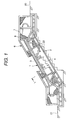
- FIG. 1 is a side view showing a first embodiment of a curing system for a passenger conveyer in accordance with the present invention.
- FIG. 2 is an enlarged cross-sectional view showing the I-portion of FIG. 1.
- FIG. 3 is a view showing the state that the curing system shown in FIG. 2 is attached to a frame composing the main body of the passenger conveyer.
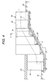
- FIG. 4 is a side view showing a second embodiment in accordance with the present invention.
- FIG. 5 is an enlarged cross-sectional view showing the II-portion of FIG. 4.
- FIG. 6 is a cross-sectional view showing a main portion of a third embodiment in accordance with the present invention.
- FIG. 1 to FIG. 3 An embodiment of a curing system for a passenger conveyer in accordance with the present invention will be described below, referring to FIG. 1 to FIG. 3.
- the curing system 6 composing the first embodiment is arranged so as to cover over the whole side area in one side of the passenger conveyer, for example, the escalator to be cured.
- the escalator 1 comprises a frame 2 forming the main body rising up, for example, to a position of a balustrade 3, steps 4, hand rails 5 and so on.
- the curing system 6 covering the whole side area in one side portion of the escalator comprises a frame body 7; a sheet-shaped body, for example, a net body 8 attached to the frame body 7; and projecting parts 9, 10 by which the frame body 7 is fixed to, for example, the frame 2 of the escalator 1.
- Holes 11, 12 provided in the projecting parts 9, 10 are fit to holes 13, 14 provided in the frame 2, respectively, and the curing system 6 is supported by the escalator 1 by inserting a bolt 15 into the holes 11, 13 and a bolt 16 into the holes 12, 14 and fastening the bolts 15, 16.
- a holding means for holding the curing system 6 to the passenger conveyer 1 itself that is, a fixing means for fixing the curing system 6 to the frame 2 composing the main body of the escalator 1 is composed of the projecting parts 9, 10; the holes 11, 12 in the projecting parts 9, 10; the holes 13, 14 formed in the frame 2; and the bolts 15, 16.
- the first embodiment constructed as described above restricts equipment, machines, work tools to project from the outside of the escalator 1, and accordingly it is possible to protect the environment around the escalator 1. Therefore, during the installation work or the repairing work, it is possible to secure the safety and the protection to pedestrians walking, for example, on the staircase 22.
- the curing system 6 can be formed in a simple structure with less number of members since the leg bodies need not to be set up on the floor surface of the upper floor 20, the floor surface of the lower floor 21 and the staircase 22. Further, it is possible to reduce the total volume of the curing system by the amount of the leg bodies, and it is easy to handle the curing system in transportation and management. Furthermore, the area around the escalator 1 can be kept relatively wider, and the restriction to the pedestrian zone can be moderated.
- the first embodiment described above comprises the holes 11, 12 in the frame 2, the holes 13, 14 formed in the frame 2 and bolts 15, 16 as the fixing means for fixing the curing system 6 to the frame 2
- the curing system 6 may be fixed to the frame 2 by welding the projecting parts 9, 10 to the frame 2 without providing the holes 11, 12, 13, 14 and the bolts 15, 16.
- number of the projecting parts 9, 10 in the frame body 7 may be appropriately determined depending on necessity.
- the first embodiment described above basically comprises only the curing system 6, a lighting fixture, a ventilation unit and so on may be added.
- FIG. 4 A second embodiment in accordance with the present invention will be describe below, referring to FIG. 4 and FIG. 5.
- the passenger conveyer to be cured is also an escalator 1 installed on a staircase 22 arranged between an upper floor 20 and a lower floor 21 in a building, similarly to the first embodiment described above, and the second embodiment has a curing system 30 covering over the whole side area in one side of the escalator 1.
- the curing system 30 comprises a frame body 31, plate-shaped bodies, that is, panels 32 having solidity to be attached to the frame body 31, and extension parts 39 extending the panels 32 up to near a ceiling part 23 of a building.
- the curing system comprises projecting parts 33, 34 in the frame body 31, holes 35, 36 provided in the projecting parts 33, 34, holes formed in the frame 2 so as to fit to the holes 35, 36 and bolts 37, 38 to be inserted into the corresponding holes.
- a holding means for holding the curing system 30 to the passenger conveyer 1 itself that is, a fixing means for fixing the curing system 30 to the frame 2 composing the main body of the escalator 1 is composed of the projecting parts 33, 34 in the frame body 31; the holes 35, 36 and so on; and the bolts 37, 38.
- the second embodiment constructed as described above can also perform curing of the escalator 1 without any leg bodies to be set up on the upper floor 20, the lower floor 21 and the staircase 22, and has the operation and the effects similar to those of the first embodiment described above.
- the extension parts 39 of the curing system 30 cover the wider range extending up to near a ceiling part 23 of a building, it is possible to more certainly protect the environment around the escalator 1 during installation work or repairing work of the escalator 1. Therefore, it is possible to more certainly secure the safety and the protection to pedestrians walking on the staircase 22.
- FIG. 6 shows a third embodiment in accordance with the present invention.
- the frame body 31 comprises a hook-shaped hooking part 41 as well as the projecting part 33.
- a hole 35 is formed in the projecting part 33, and a hole fit to the hole 35 is formed at the corresponding position in the frame 2.
- a bolt 37 is inserted into the hole 35 and the hole.
- a hook-shaped hooking part 40 for hooking the above-mentioned hooking part 41 is provided in the frame 2.
- the other structures are similar to those in the second embodiment described above.
- the above-mentioned hooking part 41 in the frame body 31 and the hooking part 40 in the frame 2 compose a holding means for holding the curing system 30 to the escalator 1 itself, that is, a hooking means for hooking the curing system 30 to the frame 2.
- the hooking part 41 in the frame body 31 is initially hooked to the hooking part 40 in the frame 2, and the hole 35 of the projecting part 33 in the frame body 31 is fit to the hole formed in the frame 2, and then the bolt 37 is inserted the hole 35 and the hole and fastened.
- the third embodiment constructed as described above can also perform curing of the escalator 1 without any leg bodies to be set up on the upper floor 20, the lower floor 21 and the staircase 22, and has the operation and the effects similar to those of the second embodiment described above.
- the bolt 37 is fastened, for example, by hand work after hooking the hooking part 41 in the frame body 31 to the hooking part 40 in the frame 2, manpower of the fastening work using the bolts can be reduced. Therefore, the attaching work of the curing system 30 can be efficiently performed.
- the third embodiment has the projecting part 33, and the projecting part 33 is fastened to the frame 2 through the bolt 37.
- a hooking part similar to the hooking part 41 is provided instead of the projecting part 33, and a hooking part to be hooked with the hooking part is provided in the frame 2.
- the curing system 6 or 30 is arranged so as to cover over the whole side area in one side of the escalator 1.
- the present invention is not limited that the curing system 6 or 30 is arranged in such a manner.
- the curing system may be arranged so as to cover a part, for example, a half of the a side area in one side of the escalator 1, or may be arranged so as to cover over the whole side area in both side of the escalator 1, or may be arranged so as to cover over the landings in the upper and the lower floors of the escalator 1, if necessary.
- the escalator 1 is taken as an example of the passenger conveyer to be cured.
- the escalator 1 may be a generally used escalator, or may be a recently developed thin escalator of which the total height is lower than that of the general escalator by 20 to 30 %.
- the curing system may be employed for a moving sidewalk instead of the escalator 1.
- the passenger conveyer is installed in a staircase in a railway station
- civil work is performed to excavate an installation place such as part of the upper and the lower floors and the staircase where the passenger conveyer is to be installed.
- a simple fence or cover is put up around the working zone so as to prevent the passengers in the railway station from entering in there.
- the passenger conveyer is brought in to be temporarily installed in the excavated portion.
- the curing system is held with the frame of the passenger conveyer to surround the working zone.
- the fourth step assembling of the remaining parts of the passenger conveyer and accurate positioning of the passenger conveyer are performed. Further, after the fourth step, the fifth step is performed to remove the curing system and to attach the exterior features of the passenger conveyer. Thus, the installation of the passenger conveyer is completed.
- the work from the first step to the fifth step described above is a procedure for newly installing a passenger conveyer.
- the curing system described above is not always necessary to be supported with the frame of the passenger conveyer and the curing system may be supported using the balustrade or the like.
- the total weight of the curing system described above is completely supported by the passenger conveyer side.
- the curing system may be set up on the floors in the upper and the lower floors and on the staircase where the passenger conveyer is installed. Thereby, the weight of the curing system is sustained by the floors and the staircase, and the passenger conveyer side only prevents the set-up curing system from falling down.
- curing of the passenger conveyer can be performed without the specifically used leg bodies to be set up on the floor surface, number of the members for the curing system can be reduced compared to the conventional curing system, and the structure of the curing system can be simplified. Thereby, the manufacturing cost can be reduced. Further, the total volume of the curing system can be reduced compared to that of the conventional curing system by the amount of eliminating the leg bodies, and the handling at transporting and managing can be easily performed. Furthermore, the area around the passenger conveyer can be kept wider compared to the conventional curing system, and accordingly the restrictions to the pedestrian zone and so on can be moderated.
Landscapes
- Engineering & Computer Science (AREA)
- Architecture (AREA)
- Civil Engineering (AREA)
- Structural Engineering (AREA)
- Escalators And Moving Walkways (AREA)
Applications Claiming Priority (2)
| Application Number | Priority Date | Filing Date | Title |
|---|---|---|---|
| JP35807599 | 1999-12-16 | ||
| JP35807599A JP3454766B2 (ja) | 1999-12-16 | 1999-12-16 | 乗客コンベアの工事方法及び乗客コンベアの養生装置 |
Publications (3)
| Publication Number | Publication Date |
|---|---|
| EP1108675A2 true EP1108675A2 (de) | 2001-06-20 |
| EP1108675A3 EP1108675A3 (de) | 2004-02-04 |
| EP1108675B1 EP1108675B1 (de) | 2012-12-12 |
Family
ID=18457415
Family Applications (1)
| Application Number | Title | Priority Date | Filing Date |
|---|---|---|---|
| EP00107688A Expired - Lifetime EP1108675B1 (de) | 1999-12-16 | 2000-04-10 | Arbeitsmethode und Schutzsystem für PERSONENFÖRDER anlage |
Country Status (6)
| Country | Link |
|---|---|
| EP (1) | EP1108675B1 (de) |
| JP (1) | JP3454766B2 (de) |
| KR (1) | KR20010066772A (de) |
| CN (1) | CN1167603C (de) |
| MY (1) | MY133186A (de) |
| TW (1) | TW522136B (de) |
Cited By (3)
| Publication number | Priority date | Publication date | Assignee | Title |
|---|---|---|---|---|
| ES2564908A1 (es) * | 2015-10-05 | 2016-03-29 | Thyssenkrupp Elevator Innovation Center, S. A. | Pasillo, rampa o escalera mecánica |
| WO2019185573A1 (de) | 2018-03-28 | 2019-10-03 | Inventio Ag | Befestigungsvorrichtung zum befestigen eines temporären wartungsgeländers an einem tragwerk einer personentransportanlage |
| WO2022258449A1 (de) | 2021-06-11 | 2022-12-15 | Inventio Ag | Tragwerk einer fahrtreppe oder eines fahrsteigs |
Families Citing this family (5)
| Publication number | Priority date | Publication date | Assignee | Title |
|---|---|---|---|---|
| CN101966961A (zh) * | 2010-10-29 | 2011-02-09 | 江南嘉捷电梯股份有限公司 | 自动扶梯或自动人行道上的护栏结构 |
| CN102838036B (zh) * | 2012-09-19 | 2014-03-26 | 苏州富士电梯有限公司 | 自动扶梯或自动人行道的进出口面板安装结构 |
| CN104310184B (zh) * | 2014-08-21 | 2017-07-11 | 西尼机电(杭州)有限公司 | 雨棚一体式自动扶梯 |
| DE102018220899A1 (de) * | 2018-12-04 | 2020-06-04 | Thyssenkrupp Ag | Balustrade für eine Personenfördervorrichtung, Personenfördervorrichtung mit einer solchen Balustrade und Verfahren zur Modernisierung einer Personenfördervorrichtung |
| US11970365B2 (en) | 2020-03-04 | 2024-04-30 | Inventio Ag | Protective device during assembly work on an escalator or a moving walkway |
Citations (2)
| Publication number | Priority date | Publication date | Assignee | Title |
|---|---|---|---|---|
| JPH04144900A (ja) | 1990-10-05 | 1992-05-19 | Toshiba Corp | エスカレータ |
| JPH07179284A (ja) | 1993-12-24 | 1995-07-18 | Hitachi Ltd | 通路設備 |
Family Cites Families (4)
| Publication number | Priority date | Publication date | Assignee | Title |
|---|---|---|---|---|
| JPH10182047A (ja) * | 1996-12-24 | 1998-07-07 | Hitachi Ltd | 乗客コンベアの透明型欄干用フェンス体 |
| JP3122625B2 (ja) * | 1997-02-20 | 2001-01-09 | 株式会社日立ビルシステム | エスカレータの養生方法および養生パネル |
| JPH10250965A (ja) * | 1997-03-14 | 1998-09-22 | Hitachi Building Syst Co Ltd | エスカレータの乗降部養生方法 |
| JPH11322250A (ja) * | 1998-05-20 | 1999-11-24 | Mitsubishi Electric Building Techno Service Co Ltd | 屋外用エスカレータの作業用安全柵 |
-
1999
- 1999-12-16 JP JP35807599A patent/JP3454766B2/ja not_active Expired - Fee Related
-
2000
- 2000-04-10 EP EP00107688A patent/EP1108675B1/de not_active Expired - Lifetime
- 2000-04-20 MY MYPI20001694A patent/MY133186A/en unknown
- 2000-04-20 KR KR1020000020919A patent/KR20010066772A/ko not_active Withdrawn
- 2000-04-24 CN CNB001069837A patent/CN1167603C/zh not_active Expired - Fee Related
- 2000-04-26 TW TW089107910A patent/TW522136B/zh not_active IP Right Cessation
Patent Citations (2)
| Publication number | Priority date | Publication date | Assignee | Title |
|---|---|---|---|---|
| JPH04144900A (ja) | 1990-10-05 | 1992-05-19 | Toshiba Corp | エスカレータ |
| JPH07179284A (ja) | 1993-12-24 | 1995-07-18 | Hitachi Ltd | 通路設備 |
Cited By (3)
| Publication number | Priority date | Publication date | Assignee | Title |
|---|---|---|---|---|
| ES2564908A1 (es) * | 2015-10-05 | 2016-03-29 | Thyssenkrupp Elevator Innovation Center, S. A. | Pasillo, rampa o escalera mecánica |
| WO2019185573A1 (de) | 2018-03-28 | 2019-10-03 | Inventio Ag | Befestigungsvorrichtung zum befestigen eines temporären wartungsgeländers an einem tragwerk einer personentransportanlage |
| WO2022258449A1 (de) | 2021-06-11 | 2022-12-15 | Inventio Ag | Tragwerk einer fahrtreppe oder eines fahrsteigs |
Also Published As
| Publication number | Publication date |
|---|---|
| JP2001171964A (ja) | 2001-06-26 |
| EP1108675A3 (de) | 2004-02-04 |
| JP3454766B2 (ja) | 2003-10-06 |
| KR20010066772A (ko) | 2001-07-11 |
| CN1167603C (zh) | 2004-09-22 |
| MY133186A (en) | 2007-10-31 |
| EP1108675B1 (de) | 2012-12-12 |
| CN1299773A (zh) | 2001-06-20 |
| TW522136B (en) | 2003-03-01 |
Similar Documents
| Publication | Publication Date | Title |
|---|---|---|
| KR101794085B1 (ko) | 다층 건물의 건축 시스템 및 방법 | |
| KR100913381B1 (ko) | 지중 수직터널 구조물용 슬립폼 및 이를 이용한 지중수직터널 구조물의 시공방법 | |
| WO2011002120A1 (ko) | 건축공사용 복합케이지 | |
| EP1108675B1 (de) | Arbeitsmethode und Schutzsystem für PERSONENFÖRDER anlage | |
| KR20190018646A (ko) | 빌딩의 현대화 방법 및 빌딩에 형성된 리프트 시스템을 구비한 구조체 | |
| KR102033453B1 (ko) | 엘리베이터 승강장 출입구의 문턱 시공방법 | |
| JP5417018B2 (ja) | 既設建物へのエレベーターの設置工法 | |
| JP6239686B2 (ja) | トンネルの立坑内部構造の構築部材、工事用リフト及び資材搬送台車 | |
| CN209891598U (zh) | 轻型预制装配式楼梯 | |
| KR102335856B1 (ko) | 철골빔 설치용 안전 난간대 | |
| JP2022097091A (ja) | 高架下足場の製造方法および送出具 | |
| EP0713942A1 (de) | Vorläufige Treppe mit Podest und Anwendungsverfahren | |
| JP6534938B2 (ja) | ライニングプレート据付兼雨養生治具及びこの治具を用いたライニングプレート据付方法 | |
| JPH06305657A (ja) | エレベーターとそのエレベーターシャフト | |
| JPH09296407A (ja) | 覆工板 | |
| JP3212231B2 (ja) | プラントの建設方法及びその建設設備 | |
| KR100683506B1 (ko) | 계단 조립체 및 그 시공방법 | |
| KR102714426B1 (ko) | 수직구의 최상단에 시공되는 가설슬래브 및 이를 이용한 지상 콘크리트 구조물의 시공방법 | |
| KR102664920B1 (ko) | 천장 구조물 설치용 전산볼트 조립체 및 그 시공방법 | |
| JP2001042076A (ja) | 原子力発電設備の建設工法 | |
| JP2004132038A (ja) | Alc床・壁構造 | |
| KR101234263B1 (ko) | 난간 설치용 지지유닛 및 이를 사용하는 난간 시공방법 | |
| JP2936043B2 (ja) | 開口工事方法、これを用いたエレベータの乗場増設工事施工方法及びこれらの方法に適する養生板 | |
| JP3228821B2 (ja) | エレベータ出入口部材の仮固定装置 | |
| JPH08303006A (ja) | 建築物のビルドアンドスクラップ式構築方法 |
Legal Events
| Date | Code | Title | Description |
|---|---|---|---|
| PUAI | Public reference made under article 153(3) epc to a published international application that has entered the european phase |
Free format text: ORIGINAL CODE: 0009012 |
|
| AK | Designated contracting states |
Kind code of ref document: A2 Designated state(s): AT BE CH CY DE DK ES FI FR GB GR IE IT LI LU MC NL PT SE |
|
| AX | Request for extension of the european patent |
Free format text: AL;LT;LV;MK;RO;SI |
|
| PUAL | Search report despatched |
Free format text: ORIGINAL CODE: 0009013 |
|
| AK | Designated contracting states |
Kind code of ref document: A3 Designated state(s): AT BE CH CY DE DK ES FI FR GB GR IE IT LI LU MC NL PT SE |
|
| AX | Request for extension of the european patent |
Extension state: AL LT LV MK RO SI |
|
| 17P | Request for examination filed |
Effective date: 20040729 |
|
| AKX | Designation fees paid |
Designated state(s): DE FR GB |
|
| 17Q | First examination report despatched |
Effective date: 20080328 |
|
| GRAP | Despatch of communication of intention to grant a patent |
Free format text: ORIGINAL CODE: EPIDOSNIGR1 |
|
| GRAS | Grant fee paid |
Free format text: ORIGINAL CODE: EPIDOSNIGR3 |
|
| GRAP | Despatch of communication of intention to grant a patent |
Free format text: ORIGINAL CODE: EPIDOSNIGR1 |
|
| GRAA | (expected) grant |
Free format text: ORIGINAL CODE: 0009210 |
|
| AK | Designated contracting states |
Kind code of ref document: B1 Designated state(s): DE FR GB |
|
| REG | Reference to a national code |
Ref country code: GB Ref legal event code: FG4D |
|
| REG | Reference to a national code |
Ref country code: DE Ref legal event code: R096 Ref document number: 60047686 Country of ref document: DE Effective date: 20130207 |
|
| PLBE | No opposition filed within time limit |
Free format text: ORIGINAL CODE: 0009261 |
|
| STAA | Information on the status of an ep patent application or granted ep patent |
Free format text: STATUS: NO OPPOSITION FILED WITHIN TIME LIMIT |
|
| 26N | No opposition filed |
Effective date: 20130913 |
|
| GBPC | Gb: european patent ceased through non-payment of renewal fee |
Effective date: 20130410 |
|
| REG | Reference to a national code |
Ref country code: DE Ref legal event code: R097 Ref document number: 60047686 Country of ref document: DE Effective date: 20130913 |
|
| PG25 | Lapsed in a contracting state [announced via postgrant information from national office to epo] |
Ref country code: DE Free format text: LAPSE BECAUSE OF NON-PAYMENT OF DUE FEES Effective date: 20131101 Ref country code: GB Free format text: LAPSE BECAUSE OF NON-PAYMENT OF DUE FEES Effective date: 20130410 |
|
| REG | Reference to a national code |
Ref country code: FR Ref legal event code: ST Effective date: 20131231 |
|
| REG | Reference to a national code |
Ref country code: DE Ref legal event code: R119 Ref document number: 60047686 Country of ref document: DE Effective date: 20131101 |
|
| PG25 | Lapsed in a contracting state [announced via postgrant information from national office to epo] |
Ref country code: FR Free format text: LAPSE BECAUSE OF NON-PAYMENT OF DUE FEES Effective date: 20130430 |