EP1108820A2 - Einbaugarnitur mit lösbarem Glockenadapter - Google Patents
Einbaugarnitur mit lösbarem Glockenadapter Download PDFInfo
- Publication number
- EP1108820A2 EP1108820A2 EP00116673A EP00116673A EP1108820A2 EP 1108820 A2 EP1108820 A2 EP 1108820A2 EP 00116673 A EP00116673 A EP 00116673A EP 00116673 A EP00116673 A EP 00116673A EP 1108820 A2 EP1108820 A2 EP 1108820A2
- Authority
- EP
- European Patent Office
- Prior art keywords
- sleeve
- installation set
- set according
- connection
- sleeve tube
- Prior art date
- Legal status (The legal status is an assumption and is not a legal conclusion. Google has not performed a legal analysis and makes no representation as to the accuracy of the status listed.)
- Granted
Links
- 238000009434 installation Methods 0.000 title claims description 46
- 230000008878 coupling Effects 0.000 claims description 17
- 238000010168 coupling process Methods 0.000 claims description 17
- 238000005859 coupling reaction Methods 0.000 claims description 17
- 238000007789 sealing Methods 0.000 claims description 4
- 239000013505 freshwater Substances 0.000 claims description 3
- 238000002372 labelling Methods 0.000 claims description 3
- 238000010276 construction Methods 0.000 description 6
- 238000004519 manufacturing process Methods 0.000 description 5
- 230000001012 protector Effects 0.000 description 5
- 230000008901 benefit Effects 0.000 description 3
- 239000007787 solid Substances 0.000 description 3
- 230000006978 adaptation Effects 0.000 description 1
- 230000015572 biosynthetic process Effects 0.000 description 1
- 238000011109 contamination Methods 0.000 description 1
- 238000005516 engineering process Methods 0.000 description 1
- 239000000463 material Substances 0.000 description 1
- 230000002787 reinforcement Effects 0.000 description 1
- XLYOFNOQVPJJNP-UHFFFAOYSA-N water Substances O XLYOFNOQVPJJNP-UHFFFAOYSA-N 0.000 description 1
Images


Classifications
-
- E—FIXED CONSTRUCTIONS
- E03—WATER SUPPLY; SEWERAGE
- E03B—INSTALLATIONS OR METHODS FOR OBTAINING, COLLECTING, OR DISTRIBUTING WATER
- E03B9/00—Methods or installations for drawing-off water
- E03B9/02—Hydrants; Arrangements of valves therein; Keys for hydrants
- E03B9/08—Underground hydrants
Definitions
- the invention relates to an installation set for those running in the road substructure Pipes, especially fresh water pipes, which end in the street cap Key bar features the bottom end in the form of a dome sleeve is releasably connected to the spindle of the line slide, the key rod is surrounded by a sleeve tube with a connection area of the coupling sleeve and spindle surrounding bell is connected.
- the bell adapter is used to connect the key rod to encapsulate and seal the dome sleeve or dome sleeve to the spindle.
- This inevitably has the disadvantage that the area of the coupling sleeve and whose connections, especially the connection of key rod and coupling sleeve in the installed set is practically inaccessible. Is so for example to loosen the connection between the installation set and the line slide, there are significant problems.
- the object of the invention is therefore to create a built-in set, which can be flexibly adapted to the installation conditions and their coupling sleeve area remains accessible.
- Each installation set can therefore be individually adapted on the construction site because the connection between the key rod and the spindle producing the coupling sleeve is accessible remains, since the bell enveloping and sealing this area at all times can be detached from the sleeve tube.
- Disadvantages compared to the previously known welded joint but do not exist because the connection between the sleeve tube and bell is tensile and otherwise stable.
- a screw, bayonet or snap connection In contrast to a welded connection, it is practically anytime, even when installed solvable.
- the area of the dome sleeve can be made accessible at any time by loosening the bell adapter from the sleeve tube.
- a preferred embodiment of such a connection is that in which Sleeve tube and bell through a plug connection secured by a safety catch are interconnected. Accordingly, the sleeve tube can be inserted into the bell trained, the safety catch also serves this connector reliable protection against high tensile loads.
- the safety catch can be designed so that the two components sleeve tube and bell when inserted into each other automatically lock together in the longitudinal direction or so that initially one Rotational movement between bell and sleeve tube is to be carried out in In this case, make safety catches not arranged in the longitudinal axis direction.
- Locking tooth and locking tooth holder can be on the outside as well as the inside of the Installation set to be arranged. Without further ado, it is also conceivable that the locking tooth Assign the sleeve tube and the locking tooth holder to the bell.
- the locking tooth is through two oppositely arranged locking lugs are formed, so that these automatically into the Snap the ratchet tooth holder into place and create a permanent, tensile connection.
- sleeve tube and bell on the top and bottom sides of a stop ring, whereby both stop rings lie on each other when assembling the components come and assigned these detent rings also locking tooth or locking tooth holder is.
- connection has a coarse thread.
- the sleeve tube and bell can be screwed together, whereby the thread is roughly made, which is not just manufacturing Brings benefits, but also takes into account that it is in this Area can come to contamination.
- a screw connection can both manufactured under workshop and construction site conditions and easily assembled and can be dismantled just as easily.
- connection is designed like a bayonet lock. Also Such a connection can be made both in the workshop and on the construction site manufacture and is suitable, the tensile forces acting on the installation set similarly good to take up like a welded joint.
- connection is designed as a locking connection.
- the sleeve tube and / or bell are included to provide corresponding locking means, which snap against each other, so that also here a tensile connection is created, in which case a pure snap connection in contrast to the one already described secured by additional latching Plug connection is given.
- the locking connection is released by handling.
- connection as Frictional connection is formed. In this case too there is a provision additional safety catch thought.
- the external thread preferably equipped with a thread is.
- the formation of only one thread is less in terms of production technology complex and especially in connection with the pollution occurring in this area advantageous. It is also possible, instead of the sleeve tube or the external thread to equip the bell or the internal thread with only one thread, if the corresponding thread is multi-start.
- a preferred embodiment of the invention provides that the sleeve tube consisting of several telescopically interconnected single sleeve tubes is trained.
- the sleeve tube is formed in two or more parts, so here too an optimal adaptation to the site conditions can take place.
- the single sleeve pipes are connected to each other by screwing, locking or bayonet-type locking connected or can also be telescopically slidable. It is therefore possible to connect individual sleeve pipes of different lengths to one another, special coupling or supplementary sleeve tubes may also be present.
- the sleeve tube can be extended with a sleeve tube extension, which has a Sleeve is connected to the sleeve tube.
- a sleeve tube extension can also afterwards inserted as an additional component between the actual sleeve tube and the bell be set.
- the connection from the sleeve tube to the sleeve tube extension suitably corresponds of the sleeve tube extension to the bell so that these components together are compatible.
- the sleeve tube extension corresponds to the sleeves in this respect formed that the sleeve tube extension snaps at one end or at both ends or has a thread. Also a bayonet lock between the lowest Single sleeve tube and the bell is conceivable.
- the individual sleeve tubes and / or the sleeves with a handle for connecting and disconnecting Sleeve tube and bell are equipped.
- the handles are designed so that with as little force as possible exerted a torque on the sleeves or the sleeve tube can be.
- Another proposal for the interchangeability of the components of a built-in set consists of the key bar with the dome sleeve or a key bar extension is detachably connected. This means that one and the same key bar can be used various KOS or VAS dome sleeves can be equipped. This eliminates the previous, very complex to install pin connection that only with the largest Effort could be solved by using the pin that fits snugly in the fit Hammer was knocked out of the hole.
- a particularly advantageous detachable connection is created when the key bar and coupling sleeve via a snap connection or a screw connection with each other are connected.
- a snap connection or a screw connection with each other are connected.
- Threaded holes are provided in which a screw is inserted.
- This screw connection can be released in a very simple manner, and at the same time it takes up space extremely low during assembly and disassembly.
- a rest connection happens in such a way that locking pins which are connected to one another via a spring on opposite sides End faces of the key bar are set up as soon as the holes automatically snap into the dome sleeve.
- the key bar is formed in several parts, with individual key bar sections connected via adapters are. These adapters are shaped as square holders and are made using a Screw connection connected to the key bar sections.
- a compact design of the square protector is achieved when the Key bar rotating sliding washer and the square cover a common unit form. To do this, the square protector advantageously does not have to be reinforced be equipped.
- the one to be used to operate the key bar Torque is much lower than in the prior art because the between Sliding disc and edge cap of the sleeve tube existing separating surface accordingly small and thus the frictional resistance is also correspondingly low.
- the locking between the sliding washer and the sleeve tube takes place in the form that the edge cap fixing the sleeve tube with resiliently arranged and / or designed Lugs is equipped and that the sliding washer with form and of the Position forth to the detents corresponding barbs is equipped.
- This Barbs like the rest, are formed by a sliding washer and square protectors Unit very solidly formed, where against the locking lugs assigned to the sleeve tube are very small and have a web-like cross-section. against The barbs of the assembly snap into place over these locking lugs, the sleeve tube advantageously made of a more flexible, less expensive plastic can be.
- Installation-specific data and information can be particularly good place where between the one that forms the upper end of the edge cap Sealing washer and the sliding washer a labeling disc is arranged.
- This label can also be designed to accommodate a machine-readable transponder his.
- the installation set according to the invention is characterized in particular by that it can be disassembled into many individual components and thus only individually when it is installed needs to be put together. While previously complete installation sets delivered, it is now possible to provide individual parts and, if necessary, exchange with each other.
- the individual sleeve tubes over sleeves with each other are connected as well as a particularly solid, made of sliding washer and Square protector existing unit, which in existing lugs on the sleeve tube is designed to snap in, is also the connection area of the coupling sleeve and Bell enveloping spindle can be screwed or locked to the lowest single-sleeve tube educated. This creates a modular system, with a built-in set only compiled at the latest possible time immediately before installation are needed.
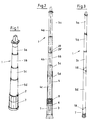
- Fig. 1 shows a built-in set 1 in a perspective view.
- the sleeve tube 5 consists of three individual sleeve tubes 5a, 5b, 5c, 5d.
- the lower single sleeve tube 5d is with the bell 7, which surrounds the connection area of the coupling sleeve and spindle a plug connection is connected and a safety catch 2 is secured.
- the individual sleeve tubes 5a, 5b, 5c and 5d have pull-out safeguards 29, 29 ' on, which are formed correspondingly in adjacent individual sleeve tubes.
- the connection 8 between the lowest single sleeve tube 5d and bell 7 is in the embodiment 2 formed by a screw connection.
- Bell 7 is in the connection area 6 arranged between key rod 4 and coupling sleeve 3.
- the view 2 shows that the installation set 1 according to the invention consists of many individual, there are interconnectable components that correspond to a modular system only need to be put together during installation.
- FIG. 3 an installation set 1 is shown, in which the individual sleeve pipes 5c and 5d are connected to one another via a latching connection 18, as are the individual sleeve tubes 5c and 5d are connected by a latch 18.
- connection 8 between the lower individual sleeve tube 5d and the bell 7 is shown in FIG. 4. It is a screw connection, the bell 7 on the End 12 facing sleeve tube is equipped with an internal thread 9. Correspondence The external thread 10 is at the end 11 of the bell 7 facing the bell Sleeve tube 5d formed. This creates a tensile but detachable connection 8. Das Internal thread 9 has only one thread 20, for which manufacturing reasons speak. It also takes into account the fact that pollution can occur at these points.
- the individual sleeve tubes 5c and 5d are in this Case telescopically slidable. On key bar and Dome sleeve has been omitted in this illustration.
- FIG. 5 A longitudinal section through an installation set 1 in this area also shows Fig. 5, where also a key rod 4 with a detachably connected to this coupling sleeve 3 is shown.
- These components can be put together just as individually as this is the case between the sleeve tube 5 and the bell 7. Between these components is the Connection 8 a screw connection.
- the connection area 6 between the key bar 4 and dome sleeve 3, which is encased by the bell 7, sealed and protected remains accessible even after installing the installation set 1.
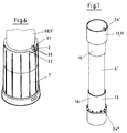
- Fig. 6 shows a bell 7, which with the lower sleeve tube 5d or one Sleeve tube extension 5 'is connected by a plug connection.
- This connector is additionally secured against tension by a safety catch 2.
- This is what Sleeve tube 5d a locking tooth receptacle 32 and the bell 7 corresponding to it trained locking tooth 31 assigned.
- the locking tooth 31 is opposite by two arranged locking lugs 35 formed automatically in the locking tooth receptacle 32nd engage, especially since they are arranged in the longitudinal axis direction of the installation set.
- sleeves 13 are also attached to one in FIG Sheathed tube extension 5 'shown, which serve as push-in sleeves, which have an additional locking 34 are secured.
- a single sleeve pipe with a screw connection is shown as it Sleeve tube extension 5 'is used.
- screw sockets 17 are equipped with handles 14 in order to be easily released to be able to.
- Fig. 10 shows a sleeve tube cap 30, which is a particularly advantageous construction having.
- the unit consisting of square protector 21 and sliding washer 23 22 is particularly solid and engages with its barbs 25 in the edge cap 28 assigned locking lugs 24, which are arranged and / or formed resiliently are.
- the sleeve tube 5 is made of a relatively soft and flexible Material made. That for actuating the key bar, not shown here Torque to be applied can be relatively low because the assembly 22 is extreme is smooth.
Landscapes
- Health & Medical Sciences (AREA)
- Life Sciences & Earth Sciences (AREA)
- Engineering & Computer Science (AREA)
- Hydrology & Water Resources (AREA)
- Public Health (AREA)
- Water Supply & Treatment (AREA)
- Mutual Connection Of Rods And Tubes (AREA)
- Catching Or Destruction (AREA)
- Telephone Function (AREA)
- Coupling Device And Connection With Printed Circuit (AREA)
- Oscillators With Electromechanical Resonators (AREA)
- Diaphragms For Electromechanical Transducers (AREA)
- Accessories Of Cameras (AREA)
- Tents Or Canopies (AREA)
- Quick-Acting Or Multi-Walled Pipe Joints (AREA)
Abstract
Description
- Fig. 1
- eine Einbaugarnitur in perspektivischer Ansicht,
- Fig. 2
- eine Einbaugarnitur im Längsschnitt,
- Fig. 3
- eine Einbaugarnitur in perspektivischer Ansicht,
- Fig. 4
- die Schraubverbindung zwischen Glocke und Hülsrohr,
- Fig. 5
- den Längsschnitt durch eine Glocke mit Anschlüssen,
- Fig. 6
- die Steckverbindung zwischen Glocke und Hülsrohr
- Fig. 7
- ein Einzelhülsrohr mit Steckverbindung
- Fig. 8
- ein Einzelhülsrohr mit Schraubverbindung,
- Fig. 9
- ein Einzelhülsrohr im Schnitt und
- Fig. 10
- die geschnittene, perspektivische Ansicht einer Hülsrohrkappe.
Claims (19)
- Einbaugarnitur (1) für im Straßenunterbau verlaufende Leitungen, insbesondere Frischwasserleitungen, die über eine in der Straßenkappe endende Schlüsselstange (4) verfügt, die mit ihrem unteren Ende in Form einer Kuppelmuffe (3) mit der Spindel des Leitungsschiebers lösbar verbunden ist, wobei die Schlüsselstange (4) von einem Hülsrohr (5) umgeben ist, das mit einer den Anschlussbereich (6) von Kuppelmuffe (3) und Spindel umgebenden Glocke (7) verbunden ist,
dadurch gekennzeichnet,
dass Hülsrohr (5) und Glocke (7) eine zugfeste und lösbar ausgebildete Verbindung (8) aufweisend ausgebildet sind. - Einbaugarnitur nach Anspruch 1,
dadurch gekennzeichnet,
dass Hülsrohr (5) und Glocke (7) durch eine durch eine Sicherheitsverrastung (2) gesicherte Steckverbindung miteinander verbunden sind. - Einbaugarnitur nach Anspruch 2,
dadurch gekennzeichnet,
dass die Sicherheitsverrastung (2) durch einen der Glocke (7) zugeordneten Rastzahn (31) und eine dem Hülsrohr (5) zugeordnete Rastzahnaufnahme (32) gebildet ist. - Einbaugarnitur nach Anspruch 1,
dadurch gekennzeichnet,
dass die Verbindung (8) über ein Grobgewinde (9,10) verfügend ausgebildet ist. - Einbaugarnitur nach Anspruch 1,
dadurch gekennzeichnet,
dass die Verbindung bajonettverschlussartig ausgebildet ist. - Einbaugarnitur nach Anspruch 1,
dadurch gekennzeichnet,
dass die Verbindung als Rastverbindung (18) ausgebildet ist. - Einbaugarnitur nach einem oder mehreren der vorhergehenden Ansprüche,
dadurch gekennzeichnet,
dass die Verbindung als Reibschlußverbindung ausgebildet ist. - Einbaugarnitur nach einem oder mehreren der vorhergehenden Ansprüche,
dadurch gekennzeichnet,
dass die Glocke (7) an ihrem dem Hülsrohr (5) zugewandten Ende (11) ein Innengewinde (9) aufweist und dass das Hülsrohr (5) an seinem der Glocke (7) zugewandten Ende (12) ein Außengewinde (10) aufweist, wobei das Außengewinde (10) vorzugsweise mit einem Gewindegang (20) ausgestattet ist. - Einbaugarnitur nach einem oder mehreren der vorhergehenden Ansprüche,
dadurch gekennzeichnet,
dass das Hülsrohr (5) aus mehreren, teleskopierbar miteinander verbundenen Einzelhülsrohren (5a, 5b, 5c, 5d) bestehend ausgebildet ist. - Einbaugarnitur nach einem oder mehreren der vorhergehenden Ansprüche,
dadurch gekennzeichnet,
dass das Hülsrohr (5) mit einer Hülsrohrverlängerung (5') verlängerbar ist, welche über eine Muffe (13) mit dem Hülsrohr (5) verbunden ist. - Einbaugarnitur nach einem oder mehreren der vorhergehenden Ansprüche,
dadurch gekennzeichnet,
dass die Muffen (13) als durch eine Zusatzverrastung (34) gesicherte Steckmuffe (33) oder als Schraubmuffe (17) ausgebildet sind. - Einbaugarnitur nach einem oder mehreren der vorhergehenden Ansprüche,
dadurch gekennzeichnet,
dass die Hülsrohrverlängerung (5') an einem Ende (15) oder an beiden Enden (15, 16) Einrastungen oder ein Gewinde aufweist. - Einbaugarnitur nach einem oder mehreren der vorhergehenden Ansprüche,
dadurch gekennzeichnet,
dass die Einzelhülsrohre (5a, 5b, 5c, 5d) und/oder die Muffen (13) mit einer Handhabe (14) zum Verbinden und Lösen von Hülsrohr (5) und Glocke (7) ausgerüstet sind. - Einbaugarnitur nach einem oder mehreren der vorhergehenden Ansprüche,
dadurch gekennzeichnet,
dass die Schlüsselstange (4) mit der Kuppelmuffe (3) oder einer Schlüsselstangenverlängerung lösbar verbunden ist. - Einbaugarnitur nach einem oder mehreren der vorhergehenden Ansprüche,
dadurch gekennzeichnet,
dass Schlüsselstange (4) und Kuppelmuffe (3) über eine Rastverbindung oder eine Schraubverbindung miteinander verbunden sind. - Einbaugarnitur nach einem oder mehreren der vorhergehenden Ansprüche,
dadurch gekennzeichnet,
dass Schlüsselstange (4) und Schlüsselstangenverlängerung über Adapter miteinander verbunden sind. - Einbaugarnitur nach einem oder mehreren der vorhergehenden Ansprüche,
dadurch gekennzeichnet,
dass die mit der Schlüsselstange (4) drehende Gleitscheibe (23) und der Vierkantschoner (21) eine gemeinsame Baueinheit (22) bilden. - Einbaugarnitur nach einem oder mehreren der vorhergehenden Ansprüche,
dadurch gekennzeichnet,
dass die das Hülsrohr (5) fixierende Randkappe (28) mit nachgiebig angeordneten und/oder ausgebildeten Rastnasen (24) ausgerüstet ist und dass die Gleitscheibe (23) mit formmäßig und von der Position her zu den Rastnasen korrespondierenden Widerhaken ausgerüstet ist. - Einbaugarnitur nach einem oder mehreren der vorhergehenden Ansprüche,
dadurch gekennzeichnet,
dass zwischen der den oberen Abschluss der Randkappe (28) bildenden Dichtscheibe (26) und der Gleitscheibe (23) eine Beschriftungsscheibe (27) angeordnet ist.
Priority Applications (1)
| Application Number | Priority Date | Filing Date | Title |
|---|---|---|---|
| DK00116673T DK1108820T3 (da) | 1999-12-17 | 2000-08-02 | Indbygningsarmatur med aftagelig klokkeadapter |
Applications Claiming Priority (2)
| Application Number | Priority Date | Filing Date | Title |
|---|---|---|---|
| DE19961418A DE19961418C2 (de) | 1999-12-17 | 1999-12-17 | Einbaugarnitur mit lösbarem Glockenadapter |
| DE19961418 | 1999-12-17 |
Publications (3)
| Publication Number | Publication Date |
|---|---|
| EP1108820A2 true EP1108820A2 (de) | 2001-06-20 |
| EP1108820A3 EP1108820A3 (de) | 2002-11-20 |
| EP1108820B1 EP1108820B1 (de) | 2004-11-24 |
Family
ID=7933400
Family Applications (1)
| Application Number | Title | Priority Date | Filing Date |
|---|---|---|---|
| EP00116673A Expired - Lifetime EP1108820B1 (de) | 1999-12-17 | 2000-08-02 | Einbaugarnitur mit lösbarem Glockenadapter |
Country Status (6)
| Country | Link |
|---|---|
| EP (1) | EP1108820B1 (de) |
| AT (1) | ATE283395T1 (de) |
| CZ (1) | CZ298361B6 (de) |
| DE (2) | DE19961418C2 (de) |
| DK (1) | DK1108820T3 (de) |
| PL (1) | PL194010B1 (de) |
Families Citing this family (3)
| Publication number | Priority date | Publication date | Assignee | Title |
|---|---|---|---|---|
| DE20217513U1 (de) | 2002-11-13 | 2003-01-16 | Ernst Schmieding GmbH & Co. KG, 59439 Holzwickede | Adapter für ein Armaturenbetätigungsgestänge |
| DE102006048579A1 (de) * | 2006-10-13 | 2008-04-17 | Hawle Armaturen Gmbh | Einbaugarnitur-Teleskopadaptersatz |
| DE102021128619A1 (de) | 2021-11-03 | 2023-05-04 | Schönborner Armaturen GmbH | Einbaugarnitur |
Citations (1)
| Publication number | Priority date | Publication date | Assignee | Title |
|---|---|---|---|---|
| DE4438205C2 (de) | 1994-10-26 | 1998-12-03 | Michael Buhla | Einbaugarnitur mit Schnellspannkuppelmuffe |
Family Cites Families (6)
| Publication number | Priority date | Publication date | Assignee | Title |
|---|---|---|---|---|
| US5115833A (en) * | 1991-08-13 | 1992-05-26 | Harold Himle | Ground hydrant with ninety-degree water flow turn-off ball valve below frost line |
| DE19623513A1 (de) * | 1995-11-13 | 1997-12-18 | Michael Buhla | Einbaugarnitur mit stiftfreier Spindel-Muffen-Verbindung und Abstandshalter |
| DE19703397A1 (de) * | 1997-01-30 | 1998-08-06 | Philips Patentverwaltung | Interne Gerätediagnose |
| DE19703379C1 (de) * | 1997-01-30 | 1998-05-07 | Asp Armaturen Schilling Puspas | Betätigungsgestänge |
| DE19711200C2 (de) * | 1997-03-19 | 2000-10-12 | Michael Buhla | Einbaugarnitur mit Multi-Teleskop |
| DE29907395U1 (de) * | 1999-04-28 | 1999-07-29 | Dittmann, Frank, 33758 Schloß Holte-Stukenbrock | Einbaugarnitur |
-
1999
- 1999-12-17 DE DE19961418A patent/DE19961418C2/de not_active Expired - Fee Related
-
2000
- 2000-08-02 EP EP00116673A patent/EP1108820B1/de not_active Expired - Lifetime
- 2000-08-02 DE DE50008739T patent/DE50008739D1/de not_active Expired - Lifetime
- 2000-08-02 AT AT00116673T patent/ATE283395T1/de active
- 2000-08-02 DK DK00116673T patent/DK1108820T3/da active
- 2000-08-31 PL PL342285A patent/PL194010B1/pl unknown
- 2000-09-21 CZ CZ20003494A patent/CZ298361B6/cs not_active IP Right Cessation
Patent Citations (1)
| Publication number | Priority date | Publication date | Assignee | Title |
|---|---|---|---|---|
| DE4438205C2 (de) | 1994-10-26 | 1998-12-03 | Michael Buhla | Einbaugarnitur mit Schnellspannkuppelmuffe |
Also Published As
| Publication number | Publication date |
|---|---|
| DE19961418A1 (de) | 2001-07-05 |
| PL342285A1 (en) | 2001-06-18 |
| DE19961418C2 (de) | 2002-07-11 |
| DE50008739D1 (de) | 2004-12-30 |
| EP1108820A3 (de) | 2002-11-20 |
| CZ20003494A3 (cs) | 2002-01-16 |
| PL194010B1 (pl) | 2007-04-30 |
| DK1108820T3 (da) | 2005-03-29 |
| EP1108820B1 (de) | 2004-11-24 |
| ATE283395T1 (de) | 2004-12-15 |
| CZ298361B6 (cs) | 2007-09-05 |
Similar Documents
| Publication | Publication Date | Title |
|---|---|---|
| DE202013103517U1 (de) | Befestigungsanordnung für einen Wasserhahn | |
| DE4438205A1 (de) | Einbaugarnitur mit Schnellspannkuppelmuffe | |
| EP0717156A1 (de) | Höhenverstellbarer Hydrant | |
| DE19961412C2 (de) | Einbaugarnitur mit lösbarer Kuppelmuffenverbindung | |
| DE19961418C2 (de) | Einbaugarnitur mit lösbarem Glockenadapter | |
| DE19540111B4 (de) | Elektronik- und Instrumentierungsgehäuse | |
| DE3133267C2 (de) | Wasserauslauf-Armatur, insbesondere für sanitäre Zwecke | |
| DE3401427A1 (de) | Tuerpuffer | |
| DE29515370U1 (de) | Handlauf, insbesondere zur Befestigung an Geländern und Gebäudewänden | |
| EP0708209B1 (de) | Bausatz von rohrförmigen Armaturen für die Wasserleitungs-, Sanitär-, Heizungs-, Gasleitungstechnik u.dgl. | |
| DE19961420C2 (de) | Einbaugarnitur mit verbesserter Verrastung | |
| DE102005002627A1 (de) | Duscheinrichtung | |
| DE102004061168B4 (de) | Einbaugarnitur | |
| DE102012201693B4 (de) | Adapterelement | |
| EP1918467A1 (de) | Revisionsschacht für Spülkasten | |
| DE102012109033B4 (de) | Anschlussvorrichtung | |
| DE10057229B4 (de) | Wandanschlussfitting für Armaturen | |
| DE102022122848B3 (de) | Verbindungsklammer sowie Einbaugarnitur | |
| WO2019193016A1 (de) | Auslegerarm mit innen liegender rohrhalterverschraubung | |
| DE19920208C1 (de) | Verbindung einer Schlüsselstange mit der Spindel einer Absperrarmatur | |
| DE10119988A1 (de) | Verdübelungs-Vorrichtung für die Ringelemente einer Tübbingauskleidung für unterirdische Bauwerke | |
| CH686452A5 (de) | Einrichtung als Einleglehre. | |
| DE19548163C1 (de) | Vorrichtung zur Fixierung einer Hauseinführungskombination in einem Durchbruch einer Gebäudewand | |
| EP4119737A1 (de) | Rückhaltevorrichtung insbesondere für den wasserablauf von flachdächern | |
| DE29721397U1 (de) | System zur Verwendung im Betonbau für die Herstellung von Durchführungen |
Legal Events
| Date | Code | Title | Description |
|---|---|---|---|
| PUAI | Public reference made under article 153(3) epc to a published international application that has entered the european phase |
Free format text: ORIGINAL CODE: 0009012 |
|
| AK | Designated contracting states |
Kind code of ref document: A2 Designated state(s): AT BE CH CY DE DK ES FI FR GB GR IE IT LI LU MC NL PT SE |
|
| AX | Request for extension of the european patent |
Free format text: AL;LT;LV;MK;RO;SI |
|
| 17P | Request for examination filed |
Effective date: 20011115 |
|
| PUAL | Search report despatched |
Free format text: ORIGINAL CODE: 0009013 |
|
| AK | Designated contracting states |
Kind code of ref document: A3 Designated state(s): AT BE CH CY DE DK ES FI FR GB GR IE IT LI LU MC NL PT SE |
|
| AX | Request for extension of the european patent |
Free format text: AL;LT;LV;MK;RO;SI |
|
| 17Q | First examination report despatched |
Effective date: 20030218 |
|
| AKX | Designation fees paid |
Designated state(s): AT BE CH CY DE DK ES FI FR GB GR IE IT LI LU MC NL PT SE |
|
| GRAP | Despatch of communication of intention to grant a patent |
Free format text: ORIGINAL CODE: EPIDOSNIGR1 |
|
| GRAS | Grant fee paid |
Free format text: ORIGINAL CODE: EPIDOSNIGR3 |
|
| GRAA | (expected) grant |
Free format text: ORIGINAL CODE: 0009210 |
|
| AK | Designated contracting states |
Kind code of ref document: B1 Designated state(s): AT BE CH CY DE DK ES FI FR GB GR IE IT LI LU MC NL PT SE |
|
| PG25 | Lapsed in a contracting state [announced via postgrant information from national office to epo] |
Ref country code: IT Free format text: LAPSE BECAUSE OF FAILURE TO SUBMIT A TRANSLATION OF THE DESCRIPTION OR TO PAY THE FEE WITHIN THE PRESCRIBED TIME-LIMIT;WARNING: LAPSES OF ITALIAN PATENTS WITH EFFECTIVE DATE BEFORE 2007 MAY HAVE OCCURRED AT ANY TIME BEFORE 2007. THE CORRECT EFFECTIVE DATE MAY BE DIFFERENT FROM THE ONE RECORDED. Effective date: 20041124 Ref country code: NL Free format text: LAPSE BECAUSE OF FAILURE TO SUBMIT A TRANSLATION OF THE DESCRIPTION OR TO PAY THE FEE WITHIN THE PRESCRIBED TIME-LIMIT Effective date: 20041124 Ref country code: IE Free format text: LAPSE BECAUSE OF FAILURE TO SUBMIT A TRANSLATION OF THE DESCRIPTION OR TO PAY THE FEE WITHIN THE PRESCRIBED TIME-LIMIT Effective date: 20041124 Ref country code: FI Free format text: LAPSE BECAUSE OF FAILURE TO SUBMIT A TRANSLATION OF THE DESCRIPTION OR TO PAY THE FEE WITHIN THE PRESCRIBED TIME-LIMIT Effective date: 20041124 |
|
| REG | Reference to a national code |
Ref country code: GB Ref legal event code: FG4D Free format text: NOT ENGLISH |
|
| REG | Reference to a national code |
Ref country code: CH Ref legal event code: EP |
|
| REF | Corresponds to: |
Ref document number: 50008739 Country of ref document: DE Date of ref document: 20041230 Kind code of ref document: P |
|
| REG | Reference to a national code |
Ref country code: IE Ref legal event code: FG4D Free format text: GERMAN |
|
| REG | Reference to a national code |
Ref country code: CH Ref legal event code: NV Representative=s name: PA ALDO ROEMPLER |
|
| PG25 | Lapsed in a contracting state [announced via postgrant information from national office to epo] |
Ref country code: GR Free format text: LAPSE BECAUSE OF FAILURE TO SUBMIT A TRANSLATION OF THE DESCRIPTION OR TO PAY THE FEE WITHIN THE PRESCRIBED TIME-LIMIT Effective date: 20050224 Ref country code: SE Free format text: LAPSE BECAUSE OF FAILURE TO SUBMIT A TRANSLATION OF THE DESCRIPTION OR TO PAY THE FEE WITHIN THE PRESCRIBED TIME-LIMIT Effective date: 20050224 |
|
| PG25 | Lapsed in a contracting state [announced via postgrant information from national office to epo] |
Ref country code: ES Free format text: LAPSE BECAUSE OF FAILURE TO SUBMIT A TRANSLATION OF THE DESCRIPTION OR TO PAY THE FEE WITHIN THE PRESCRIBED TIME-LIMIT Effective date: 20050306 |
|
| GBT | Gb: translation of ep patent filed (gb section 77(6)(a)/1977) |
Effective date: 20050222 |
|
| REG | Reference to a national code |
Ref country code: DK Ref legal event code: T3 |
|
| NLV1 | Nl: lapsed or annulled due to failure to fulfill the requirements of art. 29p and 29m of the patents act | ||
| REG | Reference to a national code |
Ref country code: IE Ref legal event code: FD4D |
|
| PG25 | Lapsed in a contracting state [announced via postgrant information from national office to epo] |
Ref country code: LU Free format text: LAPSE BECAUSE OF NON-PAYMENT OF DUE FEES Effective date: 20050802 Ref country code: CY Free format text: LAPSE BECAUSE OF FAILURE TO SUBMIT A TRANSLATION OF THE DESCRIPTION OR TO PAY THE FEE WITHIN THE PRESCRIBED TIME-LIMIT Effective date: 20050802 |
|
| PG25 | Lapsed in a contracting state [announced via postgrant information from national office to epo] |
Ref country code: BE Free format text: LAPSE BECAUSE OF NON-PAYMENT OF DUE FEES Effective date: 20050831 Ref country code: MC Free format text: LAPSE BECAUSE OF NON-PAYMENT OF DUE FEES Effective date: 20050831 |
|
| PLBE | No opposition filed within time limit |
Free format text: ORIGINAL CODE: 0009261 |
|
| STAA | Information on the status of an ep patent application or granted ep patent |
Free format text: STATUS: NO OPPOSITION FILED WITHIN TIME LIMIT |
|
| ET | Fr: translation filed | ||
| 26N | No opposition filed |
Effective date: 20050825 |
|
| BERE | Be: lapsed |
Owner name: *KETTLER G.M.B.H. Effective date: 20050831 |
|
| PG25 | Lapsed in a contracting state [announced via postgrant information from national office to epo] |
Ref country code: PT Free format text: LAPSE BECAUSE OF NON-PAYMENT OF DUE FEES Effective date: 20050424 |
|
| REG | Reference to a national code |
Ref country code: CH Ref legal event code: PCAR Free format text: ALDO ROEMPLER PATENTANWALT;BRENDENWEG 11 POSTFACH 154;9424 RHEINECK (CH) |
|
| PGFP | Annual fee paid to national office [announced via postgrant information from national office to epo] |
Ref country code: DK Payment date: 20140826 Year of fee payment: 15 |
|
| PGFP | Annual fee paid to national office [announced via postgrant information from national office to epo] |
Ref country code: FR Payment date: 20140827 Year of fee payment: 15 |
|
| REG | Reference to a national code |
Ref country code: DK Ref legal event code: EBP Effective date: 20150831 |
|
| REG | Reference to a national code |
Ref country code: FR Ref legal event code: ST Effective date: 20160429 |
|
| PG25 | Lapsed in a contracting state [announced via postgrant information from national office to epo] |
Ref country code: DK Free format text: LAPSE BECAUSE OF NON-PAYMENT OF DUE FEES Effective date: 20150831 Ref country code: FR Free format text: LAPSE BECAUSE OF NON-PAYMENT OF DUE FEES Effective date: 20150831 |
|
| PGFP | Annual fee paid to national office [announced via postgrant information from national office to epo] |
Ref country code: GB Payment date: 20160831 Year of fee payment: 17 Ref country code: CH Payment date: 20160824 Year of fee payment: 17 |
|
| PGFP | Annual fee paid to national office [announced via postgrant information from national office to epo] |
Ref country code: AT Payment date: 20160826 Year of fee payment: 17 |
|
| REG | Reference to a national code |
Ref country code: CH Ref legal event code: PL |
|
| REG | Reference to a national code |
Ref country code: AT Ref legal event code: MM01 Ref document number: 283395 Country of ref document: AT Kind code of ref document: T Effective date: 20170802 |
|
| GBPC | Gb: european patent ceased through non-payment of renewal fee |
Effective date: 20170802 |
|
| PG25 | Lapsed in a contracting state [announced via postgrant information from national office to epo] |
Ref country code: CH Free format text: LAPSE BECAUSE OF NON-PAYMENT OF DUE FEES Effective date: 20170831 Ref country code: LI Free format text: LAPSE BECAUSE OF NON-PAYMENT OF DUE FEES Effective date: 20170831 |
|
| PG25 | Lapsed in a contracting state [announced via postgrant information from national office to epo] |
Ref country code: AT Free format text: LAPSE BECAUSE OF NON-PAYMENT OF DUE FEES Effective date: 20170802 |
|
| PG25 | Lapsed in a contracting state [announced via postgrant information from national office to epo] |
Ref country code: GB Free format text: LAPSE BECAUSE OF NON-PAYMENT OF DUE FEES Effective date: 20170802 |
|
| PGFP | Annual fee paid to national office [announced via postgrant information from national office to epo] |
Ref country code: DE Payment date: 20190829 Year of fee payment: 20 |
|
| REG | Reference to a national code |
Ref country code: DE Ref legal event code: R071 Ref document number: 50008739 Country of ref document: DE |