EP1108846A2 - Mécanisme d'entraínement d'une porte battante - Google Patents
Mécanisme d'entraínement d'une porte battante Download PDFInfo
- Publication number
- EP1108846A2 EP1108846A2 EP00127062A EP00127062A EP1108846A2 EP 1108846 A2 EP1108846 A2 EP 1108846A2 EP 00127062 A EP00127062 A EP 00127062A EP 00127062 A EP00127062 A EP 00127062A EP 1108846 A2 EP1108846 A2 EP 1108846A2
- Authority
- EP
- European Patent Office
- Prior art keywords
- swing door
- drive
- door
- lever
- articulated
- Prior art date
- Legal status (The legal status is an assumption and is not a legal conclusion. Google has not performed a legal analysis and makes no representation as to the accuracy of the status listed.)
- Granted
Links
- 210000000078 claw Anatomy 0.000 description 7
- 230000005540 biological transmission Effects 0.000 description 6
- 230000008878 coupling Effects 0.000 description 6
- 238000010168 coupling process Methods 0.000 description 6
- 238000005859 coupling reaction Methods 0.000 description 6
- 238000009434 installation Methods 0.000 description 5
- 238000010276 construction Methods 0.000 description 2
- 238000013016 damping Methods 0.000 description 2
- 238000005516 engineering process Methods 0.000 description 2
- 230000007246 mechanism Effects 0.000 description 2
- 238000004026 adhesive bonding Methods 0.000 description 1
- 150000001875 compounds Chemical class 0.000 description 1
- 230000006835 compression Effects 0.000 description 1
- 238000007906 compression Methods 0.000 description 1
- 230000005611 electricity Effects 0.000 description 1
- 230000002349 favourable effect Effects 0.000 description 1
- 230000009760 functional impairment Effects 0.000 description 1
- 238000007373 indentation Methods 0.000 description 1
- 238000005259 measurement Methods 0.000 description 1
- 238000004091 panning Methods 0.000 description 1
- 230000009467 reduction Effects 0.000 description 1
- 239000007787 solid Substances 0.000 description 1
- 230000007704 transition Effects 0.000 description 1
- 238000003466 welding Methods 0.000 description 1
Images




Classifications
-
- E—FIXED CONSTRUCTIONS
- E05—LOCKS; KEYS; WINDOW OR DOOR FITTINGS; SAFES
- E05F—DEVICES FOR MOVING WINGS INTO OPEN OR CLOSED POSITION; CHECKS FOR WINGS; WING FITTINGS NOT OTHERWISE PROVIDED FOR, CONCERNED WITH THE FUNCTIONING OF THE WING
- E05F15/00—Power-operated mechanisms for wings
- E05F15/60—Power-operated mechanisms for wings using electrical actuators
- E05F15/603—Power-operated mechanisms for wings using electrical actuators using rotary electromotors
- E05F15/611—Power-operated mechanisms for wings using electrical actuators using rotary electromotors for swinging wings
- E05F15/63—Power-operated mechanisms for wings using electrical actuators using rotary electromotors for swinging wings operated by swinging arms
-
- E—FIXED CONSTRUCTIONS
- E05—LOCKS; KEYS; WINDOW OR DOOR FITTINGS; SAFES
- E05F—DEVICES FOR MOVING WINGS INTO OPEN OR CLOSED POSITION; CHECKS FOR WINGS; WING FITTINGS NOT OTHERWISE PROVIDED FOR, CONCERNED WITH THE FUNCTIONING OF THE WING
- E05F15/00—Power-operated mechanisms for wings
- E05F15/60—Power-operated mechanisms for wings using electrical actuators
- E05F15/603—Power-operated mechanisms for wings using electrical actuators using rotary electromotors
- E05F15/611—Power-operated mechanisms for wings using electrical actuators using rotary electromotors for swinging wings
- E05F15/616—Power-operated mechanisms for wings using electrical actuators using rotary electromotors for swinging wings operated by push-pull mechanisms
- E05F15/619—Power-operated mechanisms for wings using electrical actuators using rotary electromotors for swinging wings operated by push-pull mechanisms using flexible or rigid rack-and-pinion arrangements
-
- E—FIXED CONSTRUCTIONS
- E05—LOCKS; KEYS; WINDOW OR DOOR FITTINGS; SAFES
- E05Y—INDEXING SCHEME ASSOCIATED WITH SUBCLASSES E05D AND E05F, RELATING TO CONSTRUCTION ELEMENTS, ELECTRIC CONTROL, POWER SUPPLY, POWER SIGNAL OR TRANSMISSION, USER INTERFACES, MOUNTING OR COUPLING, DETAILS, ACCESSORIES, AUXILIARY OPERATIONS NOT OTHERWISE PROVIDED FOR, APPLICATION THEREOF
- E05Y2201/00—Constructional elements; Accessories therefor
- E05Y2201/20—Brakes; Disengaging means; Holders; Stops; Valves; Accessories therefor
- E05Y2201/214—Disengaging means
- E05Y2201/216—Clutches
-
- E—FIXED CONSTRUCTIONS
- E05—LOCKS; KEYS; WINDOW OR DOOR FITTINGS; SAFES
- E05Y—INDEXING SCHEME ASSOCIATED WITH SUBCLASSES E05D AND E05F, RELATING TO CONSTRUCTION ELEMENTS, ELECTRIC CONTROL, POWER SUPPLY, POWER SIGNAL OR TRANSMISSION, USER INTERFACES, MOUNTING OR COUPLING, DETAILS, ACCESSORIES, AUXILIARY OPERATIONS NOT OTHERWISE PROVIDED FOR, APPLICATION THEREOF
- E05Y2201/00—Constructional elements; Accessories therefor
- E05Y2201/20—Brakes; Disengaging means; Holders; Stops; Valves; Accessories therefor
- E05Y2201/23—Actuation thereof
- E05Y2201/246—Actuation thereof by auxiliary motors, magnets, springs or weights
-
- E—FIXED CONSTRUCTIONS
- E05—LOCKS; KEYS; WINDOW OR DOOR FITTINGS; SAFES
- E05Y—INDEXING SCHEME ASSOCIATED WITH SUBCLASSES E05D AND E05F, RELATING TO CONSTRUCTION ELEMENTS, ELECTRIC CONTROL, POWER SUPPLY, POWER SIGNAL OR TRANSMISSION, USER INTERFACES, MOUNTING OR COUPLING, DETAILS, ACCESSORIES, AUXILIARY OPERATIONS NOT OTHERWISE PROVIDED FOR, APPLICATION THEREOF
- E05Y2201/00—Constructional elements; Accessories therefor
- E05Y2201/40—Motors; Magnets; Springs; Weights; Accessories therefor
- E05Y2201/46—Magnets
- E05Y2201/462—Electromagnets
-
- E—FIXED CONSTRUCTIONS
- E05—LOCKS; KEYS; WINDOW OR DOOR FITTINGS; SAFES
- E05Y—INDEXING SCHEME ASSOCIATED WITH SUBCLASSES E05D AND E05F, RELATING TO CONSTRUCTION ELEMENTS, ELECTRIC CONTROL, POWER SUPPLY, POWER SIGNAL OR TRANSMISSION, USER INTERFACES, MOUNTING OR COUPLING, DETAILS, ACCESSORIES, AUXILIARY OPERATIONS NOT OTHERWISE PROVIDED FOR, APPLICATION THEREOF
- E05Y2201/00—Constructional elements; Accessories therefor
- E05Y2201/60—Suspension or transmission members; Accessories therefor
- E05Y2201/622—Suspension or transmission members elements
- E05Y2201/71—Toothed gearing
- E05Y2201/722—Racks
-
- E—FIXED CONSTRUCTIONS
- E05—LOCKS; KEYS; WINDOW OR DOOR FITTINGS; SAFES
- E05Y—INDEXING SCHEME ASSOCIATED WITH SUBCLASSES E05D AND E05F, RELATING TO CONSTRUCTION ELEMENTS, ELECTRIC CONTROL, POWER SUPPLY, POWER SIGNAL OR TRANSMISSION, USER INTERFACES, MOUNTING OR COUPLING, DETAILS, ACCESSORIES, AUXILIARY OPERATIONS NOT OTHERWISE PROVIDED FOR, APPLICATION THEREOF
- E05Y2900/00—Application of doors, windows, wings or fittings thereof
- E05Y2900/50—Application of doors, windows, wings or fittings thereof for vehicles
- E05Y2900/53—Type of wing
- E05Y2900/546—Tailboards, tailgates or sideboards opening upwards
Definitions
- the invention relates to a swing door drive, in particular motor vehicle door drive for example (Tail) flaps, trunk lid or the like, with a drive device, and with one of the drive device loadable output device, which a connected swing door, in particular tailgate to pivoted a door axis.
- a swing door drive in particular motor vehicle door drive for example (Tail) flaps, trunk lid or the like
- a drive device for example (Tail) flaps, trunk lid or the like
- the drive device loadable output device which a connected swing door, in particular tailgate to pivoted a door axis.
- Swing door drives that are known in practice are used, for example on a hydraulic cylinder / piston arrangement back as a drive device. That is why complex, because for the required tightness of the Hydraulic medium must be taken care of and otherwise a special hydraulic medium supply is required.
- drives of this type generally have an expansive construction, what with regard to mostly cramped installation conditions is disadvantageous. Because such motor vehicle door or Swing door drives are usually in the rear fender or placed in the roof area. However, it says here only limited installation space available.
- swing door drives at the beginning described design in multiple variations (cf. DE 296 23 202 U1, DE 40 40 372 A1, EP 0 379 801 A2, US 2,833 536 A and US 4,333,269 A). There are different lines of development tracked for the panning movement mentioned to care.
- the invention is based on the technical problem, one Swing door drive of the construction described above to train that with little effort a special compact design succeeds and possible obstacles in the vehicle body with reliable operation can be easily overcome.
- the invention proposes a first alternative in a generic swing door drive before that the output device is a push rod and an articulated as well as with the swing door connected pivot lever, the Swivel lever through linear adjustment movements of the push rod causes circular arc movements and the push rod regularly in the course of these adjusting movements evades.
- these circular arc movements of the push rod these are usually rotations of the swivel lever about its lever axis, which is generally related to the Door axis of the swing door coincides.
- a rack is usually used as a push rod.
- the push rod or rack and the Swivel lever articulated to one another via a hinge, thus the mostly linear actuating movements of the Push rod or rack easily in rotations of the Swivel lever or the described circular arc movements can be transferred.
- too (slightly) curved movements of the push rod within the scope of the Invention.
- the hinge in question between the rack and the Most of the swivel lever describes an arc, and in the course of the adjusting movements of the rack.
- the radius this circular arc corresponds to the distance between the hinge and lever axis or door axis, because door axis and lever axis collapse regularly.
- the two respective end points of the arc can be arranged in a horizontal plane. Of course is also a non-horizontal one at this point Level conceivable. In any case, the two endpoints are in usually in a vertical extension. Hence the two respective endpoints of the Adjustment movements of the rack in this horizontal plane.
- the hinge the circular arc in question describes also explains that the rack in the Evasive or evasive in the course of their adjusting movements got to. Otherwise the hinge movements could not be balanced because the rack is in is usually designed as a rigid linear drive and thus a kind of crank mechanism between rack and swivel lever is present. This would only look different if the Reduce the length of the push rod in the course of the adjusting movements and would buckle if necessary, but what is complex.
- this rack is a three-point bearing between two base-side roles and a top-side role Has drive gear.
- This top-sided Drive gear usually meshes with a rod toothing the rack.
- the above three points usually clamp an at least isosceles Triangle on.
- the rack is practical between the two base-side roles and the top-side role Drive gear clamped, the drive gear engages in the rack teeth and in this way for the desired (linear) movements the rack cares.
- the rollers can be used together with a bearing bush for the Drive gear on a bearing plate so that the rotary evasion of the Rack succeeds in the course of their adjusting movements. Because this bearing plate is preferably rotatable about the drive shaft stored, what the aforementioned bearing bush ensures. This becomes closer with reference to the figure description are explained.
- the drive device usually has an electric motor, which if necessary with a gear can be equipped. Additionally belongs to the Drive device the drive gear already described.
- the swing door drive described has one extremely small number of required components, so that realizes a compact design right from the start can be.
- the Torques to be applied by the drive motor are particularly low, so that usually on a intermediate gear can be dispensed with.
- basically the drive power of the Reduce the electric motor are particularly low.
- this leads to one further reduction of the required installation volume, so that the presented swing door drive is practical anywhere in a vehicle body leaves. So are installation positions in one of the rear Fenders just as conceivable as in the roof area nearby a tailgate. Yes, even a placement in one of the front fender can be realized, for example to drive a hood.
- this applies also for side swing doors, in particular Rear doors, because then the swing door drive according to the invention There has to be room in the B-pillar, which is easy to do.
- the subject of the invention convinces with a compact design with sophisticated kinematics, so that with relatively small compared to the prior art Drive torques can be worked.
- the arcuate articulated lever arrangement preferably has at least two levers that are hinged together are, the levers are usually designed as bow levers are. These bow levers pose as circular arc segments a circular arc with preferably matching Radius represents.
- the two bow levers run with theirs connecting joint wavy with in the area of the joint defined kink angle.
- the position of the swing door forms the two bow levers preferably a continuous arc, the Length of the length of the two compound bow levers corresponds.
- crank joint moves approximately to the position at which the closed state of the swing door previously the lever joint has found.
- This articulation of the crank joint causes the articulated lever arrangement shifted as a whole, with the Swing door in your desired way open position is transferred.
- This increases the kink angle in the area of the lever joint is increasing, so that the articulated lever arrangement or the two bow levers in open position of the swing door finally an elongated or have an arcuate course.
- the two bow levers form a continuous one Circular arc with preferably the same Radius.
- the kink angle thus takes on values in the range of approx. 180 °.
- a particularly advantageous drive device is distinguished by an electric motor plus, if necessary, a transmission and optionally one connected via a disengageable coupling Output gear off.
- This clutch can be considered linear claw clutch can be engaged and disengaged.
- intermediate positions of the Swing door i.e. positions between closed and open Position.
- Swing door usually also disengaged because in this position is a normal one, possibly with a Servo locking device equipped, door lock with rotary latch and pawl for keeping this closed Position. In this way it can be achieved that possible movements of the swing door no negative Influence on the articulated lever arrangement or the output device and can exercise the drive device.
- the swing door is in half, for example open position for the transport of bulky goods to be held.
- the clutch or claw coupling between drive device and output device disengaged.
- the swing door then provide optional additional Damping devices, e.g. B. gas spring, the the swing door are connected.
- the entire swing door drive is operated advantageous using a control unit that is in the area of the dashboard or also mobile (as a remote control).
- This control unit can be at least the functions Represent "opening and closing" of the swing door.
- the aforementioned control unit also with a mostly obligatory remote control for central locking to a combined control module be summarized.
- the drive device is designed to be self-locking overall. Pinch protection can also be provided. This accesses a measurement of the torque on the Drive device or on the electric motor back. Pinched Objects correspond in this position mostly to an excessive torque or input current, which results in the drive device being switched off.
- a space-saving version of a Swing door drive can be achieved, at least the Drive device and / or the output device preferably in such areas of a trunk or cargo space installed for loading and storage purposes are not needed.
- the Drive device and / or the output device preferably in such areas of a trunk or cargo space installed for loading and storage purposes are not needed.
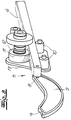
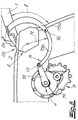
- FIGS. 1 and 4 are a swing door drive, according to the embodiment a motor vehicle door drive for a Tailgate 1 shown.
- This tailgate 1 is a component of a motor vehicle, in the present case a van.
- the Tailgate 1 can be pivoted about a door axis 2, how this is indicated by dash-dotted lines in FIGS. 1 and 4 and is visualized by an arrow.
- the swing door drive or motor vehicle door drive a drive device 3 with a drive shaft 4, which acts on an output device 5.
- an output device 5 To this Output device 5 is the tailgate 1 or swing door 1 connected.
- the output device 5 exists in the variant according to the 1 to 3 essentially from a push rod 6 and a pivoted lever 7 connected to it.
- Im Frame of the embodiment is the push rod 6 as Rack 6 executed.
- the articulated connection between this rack 6 and the pivot lever 7 is carried out via a Hinge 8.
- the tailgate is 1 with the swivel lever 7 connected.
- the hinge 8 between the Rack 6 and the pivot lever 7 in the frame of the shown For example, an arc K, in the course of (linear) movements of the rack 6.
- the radius R this circular arc K corresponds to the distance between the Hinge 8 and the lever axis or door axis 2.
- the swivel lever 7 is an exemplary embodiment executed in an arc of a circle, in accordance with the Circular arc K or the radius R. He, d. H. the swivel lever 7, one in engagement with the tailgate 1
- Have nose projection 9, which for power transmission from the drive device 3 via the output device 5 to the tailgate 1 ensures.
- the Tailgate 1 In the area of the nose projection 9 screwed the pivot lever 7.
- Other mounting options such as B. welding, riveting, gluing or the like is conceivable at this point.
- the end points A and E of the circular arc K are after Embodiment in one level, in the present case one Horizontal plane H. This moves accordingly Hinge 8 on the end of the rack 6 along the circular arc K from the starting point A to the ending point E, that is between these two endpoints A and E.
- This is kinematically particularly favorable because the solid in Fig. 1 shown starting position or the starting point A corresponds to the vertical position of the tailgate 1, during the end point E of the actuating movements of the rack 6 and thus the end point E of the hinge 8 to complete Opening of the tailgate 1 corresponds (dash-dotted Presentation).
- a three-point bearing is provided.
- Rollers 10 which support the underside of the rack 6 and a crest-side drive gear 11.
- This drive gear 11 is on the top of the rack 6 arranged and meshed with a rod toothing there. Between these three points 10 and 11 is the rack 6 practically pinched.
- the three-point bearing is in Realized the shape of an isosceles triangle.
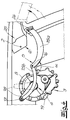
- the two bottom rollers 10 are together with one Bearing bush 12 for the drive gear 11 or the drive shaft 4 attached to at least one bearing plate 13. According to the embodiment, there are two bearing plates 13, which the drive gear 11 and the rack 6th record between them (see Fig. 2).
- the two bearing plates 13 extend according to the embodiment perpendicular to the horizontal plane H and are connected to each other, e.g. B. by riveting.
- Bearing bush 12 for the drive gear 11 and the two Bearing plates 13 these bearing plates 13 around the Turn the drive shaft 4, which passes through this bearing bush 12.
- the (vertically arranged) Bearing plates 13 rotational or swiveling movements around the drive shaft 4 in the by a double arrow in Fig. 1 indicated manner.
- the rack 6 succeeds in the course of its adjusting movements - caused by rotations of the drive gear 11 - to be able to avoid rotation, namely by the bearing bush 12 around the drive shaft 4 accordingly is rotated.
- Such swiveling movements are essential so that the hinge 8 the arc K can follow.
- the tailgate 1 With the help of the swing door drive described the tailgate 1 usually in the main or pre-locking position a motor vehicle door lock not expressly shown bring. One also not shown Closing aid then ensures a reliable one Lock the tailgate 1 and, if necessary, equalize Tolerances between drive device 3, Output device 5 and tailgate 1 off.
- the drive device 3 is not designed to be self-locking their failure also a mechanical closing of the tailgate 1 succeeds easily.
- This electric motor 14 can also in terms of Query recorded current, from what to be applied Torques can be closed. This is important if anti-trap protection is to be implemented. Of course, this can also be done with so-called anti-trap strips to be realized, as a rule are designed as conductive rubber hoses and for a Turn off at a given level of compression.
- the output device has 5 an articulated lever arrangement 15a, 15b, which to show the closed position of the swing door or tailgate 1 (see FIG. 4) buckled and its open Position (see Fig. 5) elongated or arcuate runs.
- the illustrated arcuate articulated lever arrangement 15a, 15b and the Output device 5 a more or less arcuate Movement, so that a cross bar Q in the vehicle body with the tailgate hinged to it 1 easily passed by the output device 5 or is bypassed (see. Fig. 4 and 5).
- the articulated lever arrangement 15a, 15b consists of two levers 15a, 15b, which are articulated to one another by a lever joint 16 are connected.
- a certain kink angle ⁇ which in the present case values occupies between 80 ° and 120 °.
- Both levers 15a, 15b are designed as bow levers 15a, 15b, namely as circular arc segments with the same Radius R.
- This radius R corresponds to the Embodiment of the distance between the bow levers 15a, 15b the door axis 2.
- crank joint 17 In addition to the lever joint 16 is another joint, namely a crank joint 17 realized. About this crank joint 17 is a bow lever 15b to a crank or one Crank lever 18 articulated. This crank lever 18 is acted upon by the drive device 3 in rotation.
- the drive device 3 sits down 6 and 7 from an electric motor 19 plus transmission 20th as well as a coupling 21 and one connected to it Output gear 22 together.
- the clutch 21 is a claw clutch executed and can be linearly engaged and disengaged as shown in Fig. 6 by a double arrow is indicated.
- Such a door lock can be used with a servo locking aid be equipped, the door lock after reaching one so-called pre-position (electro) motorized in the Is brought into the closed position.
- that can Door lock with a device for the so-called (electro) motorized opening, the Corresponding locking device (e.g. the pawl) lifted from the catch by means of (electro) motor power and then the respective door with the drive according to the invention is opened.
- the clutch 21 or claw clutch 21 has in detail Claws that form and / or into associated claw receptacles engage non-positively when engaging, so that then one continuous mechanical connection between the electric motor 19 and the tailgate 1 is present.
- a control unit in or on the dashboard (wireless or wired) exposure to the Electric motor 19 or 14. This allows the tailgate 1 open and close.
- Such an operating unit can also be designed as a mobile control unit and consequently wireless application of the electric motor 19, 14 enable.
- crank joint 17 sweeps an angle ⁇ of approx. 120 °, as indicated by dashed lines in Fig. 4.
- the crank joint 17 moves approximately a position previously occupied by the lever joint 16 has been.
- crank joint 17 is found in open position of the tailgate 1 (see FIG. 5) approximately where the tailgate 1 previously found the lever joint 16 (see FIG. 4).
- the transmission 20 and thus the entire drive device 3 is self-locking to prevent uncontrolled swivel movements to suppress the tailgate 1.
- FIGS. 4 to 7 are two output devices 5 on the illustrated tailgate 1 provided, namely in the area of respective hinges 25.
- Both output devices 5 can be one act on single drive device 3. Of course it is also possible to have separate drive devices 3 to be implemented per output device 5. It is also within the scope of the invention, only on one central output device 5 or articulated lever arrangement 15a, 15b to fall back on.
Landscapes
- Power-Operated Mechanisms For Wings (AREA)
- Superstructure Of Vehicle (AREA)
Applications Claiming Priority (4)
| Application Number | Priority Date | Filing Date | Title |
|---|---|---|---|
| DE19960373A DE19960373A1 (de) | 1999-12-14 | 1999-12-14 | Schwenktürantrieb, insbesondere Kraftfahrzeugtürantrieb für beispielsweise (Heck-)Klappen, Kofferraumdeckel oder dergleichen |
| DE19960373 | 1999-12-14 | ||
| DE20004973U | 2000-03-17 | ||
| DE20004973U DE20004973U1 (de) | 2000-03-17 | 2000-03-17 | Schwenktürantrieb |
Publications (3)
| Publication Number | Publication Date |
|---|---|
| EP1108846A2 true EP1108846A2 (fr) | 2001-06-20 |
| EP1108846A3 EP1108846A3 (fr) | 2003-02-05 |
| EP1108846B1 EP1108846B1 (fr) | 2006-03-01 |
Family
ID=26055813
Family Applications (1)
| Application Number | Title | Priority Date | Filing Date |
|---|---|---|---|
| EP20000127062 Expired - Lifetime EP1108846B1 (fr) | 1999-12-14 | 2000-12-11 | Mécanisme d'entraînement d'une porte battante |
Country Status (2)
| Country | Link |
|---|---|
| EP (1) | EP1108846B1 (fr) |
| DE (1) | DE50012298D1 (fr) |
Cited By (7)
| Publication number | Priority date | Publication date | Assignee | Title |
|---|---|---|---|---|
| WO2003036008A1 (fr) * | 2001-10-19 | 2003-05-01 | Valeo Sicherheitssysteme Gmbh | Mecanisme d'entrainement |
| US6955390B2 (en) | 2003-11-05 | 2005-10-18 | Siemens Aktiengesellschaft | Servo drive for activating a tailgate of a motor vehicle |
| WO2006058519A1 (fr) * | 2004-12-01 | 2006-06-08 | Webasto Ag | Systeme de volet |
| WO2006066574A1 (fr) * | 2004-12-23 | 2006-06-29 | Venset A/S | Dispositif d'ouverture/fermeture servant, par exemple, a ouvrir/fermer des fenetres |
| CN107780682A (zh) * | 2016-08-27 | 2018-03-09 | 上海宝冶集团有限公司 | 立体车库的驱动系统 |
| CN109538070A (zh) * | 2019-01-07 | 2019-03-29 | 上海北强电子有限公司 | 具有自动锁死功能的开关弧形自动门 |
| US10352080B2 (en) | 2015-08-17 | 2019-07-16 | Brose Fahrzeugteile Gmbh & Co. Kommanditgesellschaft, Bamberg | Device for manually and/or electromotively adjusting or securing a first vehicle part and a second vehicle part relative to each other |
Families Citing this family (2)
| Publication number | Priority date | Publication date | Assignee | Title |
|---|---|---|---|---|
| DE102015215630A1 (de) | 2015-08-17 | 2017-02-23 | Brose Fahrzeugteile Gmbh & Co. Kommanditgesellschaft, Bamberg | Vorrichtung zum manuellen und/oder elektromotorischen Verstellen oder Feststellen eines ersten Fahrzeugteils und eines zweiten Fahrzeugteils relativ zueinander |
| DE102015215631A1 (de) | 2015-08-17 | 2017-02-23 | Brose Fahrzeugteile Gmbh & Co. Kommanditgesellschaft, Bamberg | Vorrichtung zum manuellen und/oder elektromotorischen Verstellen oder Feststellen eines ersten Fahrzeugteils und eines zweiten Fahrzeugteils relativ zueinander |
Citations (5)
| Publication number | Priority date | Publication date | Assignee | Title |
|---|---|---|---|---|
| US2833536A (en) | 1956-11-13 | 1958-05-06 | Gen Motors Corp | Power operated rear compartment actuator and lock assembly |
| US4333269A (en) | 1979-03-16 | 1982-06-08 | Regie Nationale Des Usines Renault | Automatic control and locking device |
| EP0379801A2 (fr) | 1989-01-26 | 1990-08-01 | General Motors Corporation | Appareil de commande pour le couvercle du coffre d'un véhicule automobile |
| DE4040372A1 (de) | 1989-12-26 | 1991-06-27 | Aisin Seiki | Automatische oeffnungs- und schliessvorrichtung fuer eine heckklappe |
| DE29623202U1 (de) | 1996-10-07 | 1997-12-11 | Apprich Secur 2000 GmbH, 14974 Ludwigsfelde | Vorrichtung zum Öffnen und Verschließen einer Heckklappe eines Fahrzeuges |
Family Cites Families (1)
| Publication number | Priority date | Publication date | Assignee | Title |
|---|---|---|---|---|
| DE9015818U1 (de) * | 1990-11-20 | 1992-03-19 | Ed. Scharwächter GmbH & Co. KG, 5630 Remscheid | Antreibbares Schwenkgelenk für Klappen o.dgl. an Kraftfahrzeugen |
-
2000
- 2000-12-11 EP EP20000127062 patent/EP1108846B1/fr not_active Expired - Lifetime
- 2000-12-11 DE DE50012298T patent/DE50012298D1/de not_active Expired - Lifetime
Patent Citations (5)
| Publication number | Priority date | Publication date | Assignee | Title |
|---|---|---|---|---|
| US2833536A (en) | 1956-11-13 | 1958-05-06 | Gen Motors Corp | Power operated rear compartment actuator and lock assembly |
| US4333269A (en) | 1979-03-16 | 1982-06-08 | Regie Nationale Des Usines Renault | Automatic control and locking device |
| EP0379801A2 (fr) | 1989-01-26 | 1990-08-01 | General Motors Corporation | Appareil de commande pour le couvercle du coffre d'un véhicule automobile |
| DE4040372A1 (de) | 1989-12-26 | 1991-06-27 | Aisin Seiki | Automatische oeffnungs- und schliessvorrichtung fuer eine heckklappe |
| DE29623202U1 (de) | 1996-10-07 | 1997-12-11 | Apprich Secur 2000 GmbH, 14974 Ludwigsfelde | Vorrichtung zum Öffnen und Verschließen einer Heckklappe eines Fahrzeuges |
Cited By (8)
| Publication number | Priority date | Publication date | Assignee | Title |
|---|---|---|---|---|
| WO2003036008A1 (fr) * | 2001-10-19 | 2003-05-01 | Valeo Sicherheitssysteme Gmbh | Mecanisme d'entrainement |
| US6955390B2 (en) | 2003-11-05 | 2005-10-18 | Siemens Aktiengesellschaft | Servo drive for activating a tailgate of a motor vehicle |
| WO2006058519A1 (fr) * | 2004-12-01 | 2006-06-08 | Webasto Ag | Systeme de volet |
| WO2006066574A1 (fr) * | 2004-12-23 | 2006-06-29 | Venset A/S | Dispositif d'ouverture/fermeture servant, par exemple, a ouvrir/fermer des fenetres |
| US10352080B2 (en) | 2015-08-17 | 2019-07-16 | Brose Fahrzeugteile Gmbh & Co. Kommanditgesellschaft, Bamberg | Device for manually and/or electromotively adjusting or securing a first vehicle part and a second vehicle part relative to each other |
| CN107780682A (zh) * | 2016-08-27 | 2018-03-09 | 上海宝冶集团有限公司 | 立体车库的驱动系统 |
| CN109538070A (zh) * | 2019-01-07 | 2019-03-29 | 上海北强电子有限公司 | 具有自动锁死功能的开关弧形自动门 |
| CN109538070B (zh) * | 2019-01-07 | 2023-11-07 | 上海北强电子有限公司 | 具有自动锁死功能的开关弧形自动门 |
Also Published As
| Publication number | Publication date |
|---|---|
| EP1108846B1 (fr) | 2006-03-01 |
| EP1108846A3 (fr) | 2003-02-05 |
| DE50012298D1 (de) | 2006-04-27 |
Similar Documents
| Publication | Publication Date | Title |
|---|---|---|
| DE10114938B4 (de) | Vorrichtung zum Betätigen einer Automobil-Schwenktüre | |
| DE3815065A1 (de) | Schliesseinrichtung fuer eine haube an einem kraftfahrzeug | |
| DE102009018188B4 (de) | Vorrichtung zum automatischen Schließen einer Fahrzeugtür | |
| EP1108846B1 (fr) | Mécanisme d'entraînement d'une porte battante | |
| EP1625034A1 (fr) | Vehicule automobile | |
| EP2365171A2 (fr) | Palier d'un clapet sur un montage de véhicule automobile ainsi que carrosserie pour un tel véhicule automobile | |
| EP0716004A1 (fr) | Porte pivotante et coulissante pour véhicules de transport de personnes | |
| EP1108582A2 (fr) | Dispositif de verrouillage pour deux éléments relativement déplaçables entre eux | |
| EP1688289B1 (fr) | Dispositif pour le pivotement d'une partie d'un toit de véhicule | |
| DE19912893C2 (de) | Cabrio-Fahrzeug mit einem Verdeck | |
| EP1308375A2 (fr) | Volet de véhicule | |
| EP1072749B1 (fr) | Actionnement électromécanique pour tourillon pour le mouvement du battant d'une porte palière d'un vehicule notamment d'un vehicule de transport public. | |
| DE102005033098B4 (de) | Heckklappe für ein Kraftfahrzeug | |
| EP1509666B1 (fr) | Systeme de commande a mecanisme d'actionnement a levier concu pour faire pivoter une porte ou une trappe de vehicule | |
| DE20004973U1 (de) | Schwenktürantrieb | |
| EP1812671B1 (fr) | Dispositif de fermeture combine | |
| DE10020663A1 (de) | Dachkonstruktion für ein Kraftfahrzeug mit abhebbaren Dach | |
| DE10117769A1 (de) | Vorrichtung zur Unterstützung einer Öffnungsbewegung einer Fahrzeugklappe | |
| DE102005050419B4 (de) | Kraftwagenflügel zum Verschließen einer Karosserieöffnung | |
| DE102007035230A1 (de) | Schiebetüre für ein Fahrzeug | |
| DE102013202801B4 (de) | Einrichtung zur motorischen Betätigung einer Kraftfahrzeug-Türe mit Feststellfunktion | |
| DE10236568B4 (de) | Fahrzeug mit vertikal angeordneter Heckklappe | |
| DE102010055047B4 (de) | Bewegbares und verriegelbares Dachteil eines Fahrzeugdaches | |
| DE102005054069B4 (de) | Kraftwagenflügel zum Verschließen einer Karosserieöffnung | |
| DE4446904C1 (de) | Kraftfahrzeug-Türgriff |
Legal Events
| Date | Code | Title | Description |
|---|---|---|---|
| PUAI | Public reference made under article 153(3) epc to a published international application that has entered the european phase |
Free format text: ORIGINAL CODE: 0009012 |
|
| AK | Designated contracting states |
Kind code of ref document: A2 Designated state(s): AT BE CH CY DE DK ES FI FR GB GR IE IT LI LU MC NL PT SE TR |
|
| AX | Request for extension of the european patent |
Free format text: AL;LT;LV;MK;RO;SI |
|
| RIN1 | Information on inventor provided before grant (corrected) |
Inventor name: REDDMANN, UWE Inventor name: KOTTKE, WOLFGANG |
|
| PUAL | Search report despatched |
Free format text: ORIGINAL CODE: 0009013 |
|
| AK | Designated contracting states |
Designated state(s): AT BE CH CY DE DK ES FI FR GB GR IE IT LI LU MC NL PT SE TR |
|
| AX | Request for extension of the european patent |
Extension state: AL LT LV MK RO SI |
|
| 17P | Request for examination filed |
Effective date: 20030628 |
|
| AKX | Designation fees paid |
Designated state(s): DE ES FR GB IT |
|
| GRAP | Despatch of communication of intention to grant a patent |
Free format text: ORIGINAL CODE: EPIDOSNIGR1 |
|
| GRAS | Grant fee paid |
Free format text: ORIGINAL CODE: EPIDOSNIGR3 |
|
| GRAA | (expected) grant |
Free format text: ORIGINAL CODE: 0009210 |
|
| AK | Designated contracting states |
Kind code of ref document: B1 Designated state(s): DE ES FR GB IT |
|
| PG25 | Lapsed in a contracting state [announced via postgrant information from national office to epo] |
Ref country code: IT Free format text: LAPSE BECAUSE OF FAILURE TO SUBMIT A TRANSLATION OF THE DESCRIPTION OR TO PAY THE FEE WITHIN THE PRE;WARNING: LAPSES OF ITALIAN PATENTS WITH EFFECTIVE DATE BEFORE 2007 MAY HAVE OCCURRED AT ANY TIME BEFORE 2007. THE CORRECT EFFECTIVE DATE MAY BE DIFFERENT FROM THE ONE RECORDED.SCRIBED TIME-LIMIT Effective date: 20060301 Ref country code: GB Free format text: LAPSE BECAUSE OF FAILURE TO SUBMIT A TRANSLATION OF THE DESCRIPTION OR TO PAY THE FEE WITHIN THE PRESCRIBED TIME-LIMIT Effective date: 20060301 |
|
| REG | Reference to a national code |
Ref country code: GB Ref legal event code: FG4D Free format text: NOT ENGLISH |
|
| REF | Corresponds to: |
Ref document number: 50012298 Country of ref document: DE Date of ref document: 20060427 Kind code of ref document: P |
|
| PG25 | Lapsed in a contracting state [announced via postgrant information from national office to epo] |
Ref country code: ES Free format text: LAPSE BECAUSE OF FAILURE TO SUBMIT A TRANSLATION OF THE DESCRIPTION OR TO PAY THE FEE WITHIN THE PRESCRIBED TIME-LIMIT Effective date: 20060612 |
|
| ET | Fr: translation filed | ||
| GBV | Gb: ep patent (uk) treated as always having been void in accordance with gb section 77(7)/1977 [no translation filed] |
Effective date: 20060301 |
|
| PLBE | No opposition filed within time limit |
Free format text: ORIGINAL CODE: 0009261 |
|
| STAA | Information on the status of an ep patent application or granted ep patent |
Free format text: STATUS: NO OPPOSITION FILED WITHIN TIME LIMIT |
|
| 26N | No opposition filed |
Effective date: 20061204 |
|
| PGFP | Annual fee paid to national office [announced via postgrant information from national office to epo] |
Ref country code: FR Payment date: 20110107 Year of fee payment: 11 |
|
| REG | Reference to a national code |
Ref country code: FR Ref legal event code: ST Effective date: 20120831 |
|
| PG25 | Lapsed in a contracting state [announced via postgrant information from national office to epo] |
Ref country code: FR Free format text: LAPSE BECAUSE OF NON-PAYMENT OF DUE FEES Effective date: 20120102 |
|
| PGFP | Annual fee paid to national office [announced via postgrant information from national office to epo] |
Ref country code: DE Payment date: 20161220 Year of fee payment: 17 |
|
| REG | Reference to a national code |
Ref country code: DE Ref legal event code: R119 Ref document number: 50012298 Country of ref document: DE |
|
| PG25 | Lapsed in a contracting state [announced via postgrant information from national office to epo] |
Ref country code: DE Free format text: LAPSE BECAUSE OF NON-PAYMENT OF DUE FEES Effective date: 20180703 |