EP1108867A2 - Soupape à trois voies - Google Patents
Soupape à trois voies Download PDFInfo
- Publication number
- EP1108867A2 EP1108867A2 EP00126745A EP00126745A EP1108867A2 EP 1108867 A2 EP1108867 A2 EP 1108867A2 EP 00126745 A EP00126745 A EP 00126745A EP 00126745 A EP00126745 A EP 00126745A EP 1108867 A2 EP1108867 A2 EP 1108867A2
- Authority
- EP
- European Patent Office
- Prior art keywords
- way valve
- throttle body
- valve
- internal combustion
- combustion engine
- Prior art date
- Legal status (The legal status is an assumption and is not a legal conclusion. Google has not performed a legal analysis and makes no representation as to the accuracy of the status listed.)
- Withdrawn
Links
- 238000009826 distribution Methods 0.000 claims abstract description 11
- 238000002485 combustion reaction Methods 0.000 claims description 18
- 238000007789 sealing Methods 0.000 claims description 13
- 238000001816 cooling Methods 0.000 claims description 11
- 238000001746 injection moulding Methods 0.000 claims description 11
- 238000002347 injection Methods 0.000 claims description 9
- 239000007924 injection Substances 0.000 claims description 9
- 238000010438 heat treatment Methods 0.000 claims description 6
- 239000004033 plastic Substances 0.000 claims description 5
- 229920003023 plastic Polymers 0.000 claims description 5
- 229920001169 thermoplastic Polymers 0.000 claims description 5
- 229920001971 elastomer Polymers 0.000 claims description 2
- 239000000806 elastomer Substances 0.000 claims description 2
- 230000007613 environmental effect Effects 0.000 claims description 2
- 230000000149 penetrating effect Effects 0.000 claims description 2
- BFKJFAAPBSQJPD-UHFFFAOYSA-N tetrafluoroethene Chemical group FC(F)=C(F)F BFKJFAAPBSQJPD-UHFFFAOYSA-N 0.000 claims description 2
- 239000002826 coolant Substances 0.000 description 13
- 238000004519 manufacturing process Methods 0.000 description 5
- 239000000463 material Substances 0.000 description 5
- 238000000034 method Methods 0.000 description 4
- 238000002156 mixing Methods 0.000 description 4
- 239000004416 thermosoftening plastic Substances 0.000 description 4
- 238000004378 air conditioning Methods 0.000 description 2
- 230000002349 favourable effect Effects 0.000 description 2
- 238000003860 storage Methods 0.000 description 2
- 229910000838 Al alloy Inorganic materials 0.000 description 1
- 229910001369 Brass Inorganic materials 0.000 description 1
- OKTJSMMVPCPJKN-UHFFFAOYSA-N Carbon Chemical compound [C] OKTJSMMVPCPJKN-UHFFFAOYSA-N 0.000 description 1
- 229910001018 Cast iron Inorganic materials 0.000 description 1
- 229910001208 Crucible steel Inorganic materials 0.000 description 1
- 229910001141 Ductile iron Inorganic materials 0.000 description 1
- 229910001060 Gray iron Inorganic materials 0.000 description 1
- 229920000459 Nitrile rubber Polymers 0.000 description 1
- 239000002033 PVDF binder Substances 0.000 description 1
- 239000004743 Polypropylene Substances 0.000 description 1
- RTAQQCXQSZGOHL-UHFFFAOYSA-N Titanium Chemical compound [Ti] RTAQQCXQSZGOHL-UHFFFAOYSA-N 0.000 description 1
- 239000010951 brass Substances 0.000 description 1
- 239000000919 ceramic Substances 0.000 description 1
- 239000003795 chemical substances by application Substances 0.000 description 1
- 239000000498 cooling water Substances 0.000 description 1
- 230000003111 delayed effect Effects 0.000 description 1
- 230000001419 dependent effect Effects 0.000 description 1
- 238000004512 die casting Methods 0.000 description 1
- 238000005553 drilling Methods 0.000 description 1
- 230000000694 effects Effects 0.000 description 1
- 229920002313 fluoropolymer Polymers 0.000 description 1
- 239000010439 graphite Substances 0.000 description 1
- 229910002804 graphite Inorganic materials 0.000 description 1
- 238000003754 machining Methods 0.000 description 1
- 239000002480 mineral oil Substances 0.000 description 1
- 235000010446 mineral oil Nutrition 0.000 description 1
- 239000006223 plastic coating Substances 0.000 description 1
- 239000004810 polytetrafluoroethylene Substances 0.000 description 1
- 229920001343 polytetrafluoroethylene Polymers 0.000 description 1
- 239000004800 polyvinyl chloride Substances 0.000 description 1
- 229920002981 polyvinylidene fluoride Polymers 0.000 description 1
- 230000036316 preload Effects 0.000 description 1
- 238000004064 recycling Methods 0.000 description 1
- 239000000243 solution Substances 0.000 description 1
- 229910001220 stainless steel Inorganic materials 0.000 description 1
- 239000010935 stainless steel Substances 0.000 description 1
- 229910001256 stainless steel alloy Inorganic materials 0.000 description 1
- 239000010936 titanium Substances 0.000 description 1
- 229910052719 titanium Inorganic materials 0.000 description 1
- 238000011144 upstream manufacturing Methods 0.000 description 1
Images

Classifications
-
- F—MECHANICAL ENGINEERING; LIGHTING; HEATING; WEAPONS; BLASTING
- F01—MACHINES OR ENGINES IN GENERAL; ENGINE PLANTS IN GENERAL; STEAM ENGINES
- F01P—COOLING OF MACHINES OR ENGINES IN GENERAL; COOLING OF INTERNAL-COMBUSTION ENGINES
- F01P7/00—Controlling of coolant flow
- F01P7/14—Controlling of coolant flow the coolant being liquid
- F01P7/16—Controlling of coolant flow the coolant being liquid by thermostatic control
- F01P7/167—Controlling of coolant flow the coolant being liquid by thermostatic control by adjusting the pre-set temperature according to engine parameters, e.g. engine load, engine speed
-
- F—MECHANICAL ENGINEERING; LIGHTING; HEATING; WEAPONS; BLASTING
- F16—ENGINEERING ELEMENTS AND UNITS; GENERAL MEASURES FOR PRODUCING AND MAINTAINING EFFECTIVE FUNCTIONING OF MACHINES OR INSTALLATIONS; THERMAL INSULATION IN GENERAL
- F16K—VALVES; TAPS; COCKS; ACTUATING-FLOATS; DEVICES FOR VENTING OR AERATING
- F16K11/00—Multiple-way valves, e.g. mixing valves; Pipe fittings incorporating such valves
- F16K11/02—Multiple-way valves, e.g. mixing valves; Pipe fittings incorporating such valves with all movable sealing faces moving as one unit
- F16K11/08—Multiple-way valves, e.g. mixing valves; Pipe fittings incorporating such valves with all movable sealing faces moving as one unit comprising only taps or cocks
- F16K11/087—Multiple-way valves, e.g. mixing valves; Pipe fittings incorporating such valves with all movable sealing faces moving as one unit comprising only taps or cocks with spherical plug
- F16K11/0873—Multiple-way valves, e.g. mixing valves; Pipe fittings incorporating such valves with all movable sealing faces moving as one unit comprising only taps or cocks with spherical plug the plug being only rotatable around one spindle
-
- G—PHYSICS
- G05—CONTROLLING; REGULATING
- G05D—SYSTEMS FOR CONTROLLING OR REGULATING NON-ELECTRIC VARIABLES
- G05D23/00—Control of temperature
- G05D23/01—Control of temperature without auxiliary power
- G05D23/13—Control of temperature without auxiliary power by varying the mixing ratio of two fluids having different temperatures
- G05D23/1393—Control of temperature without auxiliary power by varying the mixing ratio of two fluids having different temperatures characterised by the use of electric means
-
- F—MECHANICAL ENGINEERING; LIGHTING; HEATING; WEAPONS; BLASTING
- F01—MACHINES OR ENGINES IN GENERAL; ENGINE PLANTS IN GENERAL; STEAM ENGINES
- F01P—COOLING OF MACHINES OR ENGINES IN GENERAL; COOLING OF INTERNAL-COMBUSTION ENGINES
- F01P7/00—Controlling of coolant flow
- F01P7/14—Controlling of coolant flow the coolant being liquid
- F01P2007/143—Controlling of coolant flow the coolant being liquid using restrictions
-
- F—MECHANICAL ENGINEERING; LIGHTING; HEATING; WEAPONS; BLASTING
- F01—MACHINES OR ENGINES IN GENERAL; ENGINE PLANTS IN GENERAL; STEAM ENGINES
- F01P—COOLING OF MACHINES OR ENGINES IN GENERAL; COOLING OF INTERNAL-COMBUSTION ENGINES
- F01P7/00—Controlling of coolant flow
- F01P7/14—Controlling of coolant flow the coolant being liquid
- F01P2007/146—Controlling of coolant flow the coolant being liquid using valves
Definitions
- the invention is based on a three-way valve according to the preamble of claim 1.
- DE 41 09 498 A1 describes an apparatus and a method for a very sensitive regulation of the temperature of a Internal combustion engine known.
- a control device several input signals, e.g. the temperature of the Internal combustion engine, the speed and load of the internal combustion engine, the vehicle speed, the operating state of a Air conditioning or the heating of the vehicle and the temperature of the cooling water.
- a setpoint generator of Control device determines taking into account the input signals a temperature setpoint for the internal combustion engine. According to a comparison of the actual values with the The control device acts on a three-way valve that in the mouth area of a bypass line in a Pipe between the internal combustion engine and a cooler is arranged. Depending on the position of the three-way valve, the Inlet flow divided between the cooling branch and the bypass.
- chick valves in the form of ball valves for setting a specific one Mixing ratio known. They are usually external driven.
- a valve plug, a throttle body is preferably with a spherical surface and with at least provided a distribution channel.
- the throttle body is in a geometrically aligned bearing bed in a valve body stored.
- the spherical throttle body is with a Drive shaft connected to the outside of the valve body is guided and is adjustable by a drive. Corresponding the position of the throttle body, the paths to the outgoing lines released, throttled or blocked.
- the ball valves are made up of individual Components assembled, with the body made of various stainless steel alloys, Gray cast iron, nodular cast iron, stainless steel cast iron, cast steel, aluminum alloys, PVC, PP, PVDF, PTFE, titanium or brass can exist. At the connection points to the lines there are seals made of fluoroplastic, ceramic, nitrile rubber, Pure elastic graphite or POM, which in turn is in Combination with different body materials a high Generate frictional torque so that high positioning forces are required and the setting is delayed.
- the throttle body of the three-way valve formed as a valve plug at least one has it penetrating distribution channel and is powered by an electric motor about the axis of rotation corresponding to one of the control unit assigned map adjustable.
- a three-way valve whose Throttle body has a spherical surface and an inner one Has distribution channel. This runs across the axis of rotation and is on a lateral surface essentially parallel to the axis of rotation open while the opposite lateral surface is closed is.
- the so formed sideways Ball valve flowing towards the axis of rotation has a comparison a more ideal solution for the ball valves flowing from below Mixing characteristic. This can be due to favorable deflection effects by the inclination of the baffle on the throttle body in returned to the areas between 60 ° and 120 ° ball rotation become. Due to the favorable characteristics and flow conditions the three-way valve is suitable for cooling circuits with electrically operated pumps. These can be smaller be dimensioned so that their power consumption is reduced and the overall efficiency improves.
- the three-way valve is operated by an electric motor via a drive shaft operated.
- This is non-rotatable with the throttle body connected; expediently it is directly on the throttle body molded while its free end is detachable with the Electric motor is connected.
- the three-way valve is advantageously a flange valve executed and mounted directly on the internal combustion engine, e.g. on the cylinder head.
- This arrangement eliminates Hose connections and the assembly effort is low. in the The area of the connections faces the valve body to the throttle body out seals made of plastic, which at the same time to Serve the throttle body.
- a spring element in shape of elastomer element, disc spring, star spring or variants of this, keeps the sealing bandage under a defined preload. On the one hand, this ensures a good seal and on the other hand tolerances or wear be balanced.
- the three-way valve is preferably in the assembly injection molding process manufactured, namely the throttle body with the Drive shaft in a first production step as an injection molded part made of thermoplastic.
- the part remains in the injection molding machine and comes with a release agent sprayed, so that in a second injection molding process introduced thermoplastic for the valve body does not connect to the throttle body and this in later valve body is rotatably mounted.
- the use of a two-component injection molding process is also possible in principle. This method is applied to by different material properties of the two injection molded parts e.g. a better friction pairing or to achieve a cheaper valve.
- a metallic one Throttle body with drive shaft or a throttle body made of plastic, which with a suitable plastic overmolded is also conceivable.
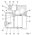
- An inlet line 34 leads from an internal combustion engine 50 for coolant to a cooler 62 which is electrically connected to a driven blower 66 cooperates.
- a return line 36 in which an electrically driven pump 64 is arranged connects the cooler 62 to the internal combustion engine 50 and thus closes a cooling circuit 48.
- On the cooling circuit 48 can a heating circuit, not shown a vehicle heating or air conditioning system.
- a bypass line 38 connects the inlet line 34 to the Return line 36. It bridges the cooler 62 and opens upstream of the pump 64 in the return line 36. Die Coolant flow is indicated by arrows.
- a three-way valve 10 is provided in the form of a plug valve, the throttle body 12 (Fig. 2) by an electric motor 54 is adjustable. This is done by a control unit 52 controlled, which via signal lines 68 with numerous, different sensors 60 is connected. The sensors 60 record operating parameters and environmental parameters of the Internal combustion engine 50 and the cooling / heating circuit 48. Off the input variables are assigned with the help of at least one Characteristic map generated a manipulated variable for the electric motor 54.
- the three-way valve 10 essentially consists from a valve body 14 and the throttle body 12 (Fig. 2). In the embodiment shown, it has a spherical shape Surface. But there are also other surface shapes conceivable, such as cylindrical or conical.
- the throttle body 12 is advantageously an injection molded part made of a thermoplastic.
- a drive shaft 16 is injection molded in one operation and an inner distribution channel 30 and a bore 42 for receiving a temperature sensor 18 formed by insert parts, which are inserted into the mold before injection molding.
- the temperature sensor 18, which is diametrical to the drive shaft 16 is arranged and protrudes into the distribution channel 30 is on easily integrated and detected in the three-way valve 10 the coolant temperature immediately in this range, i.e. in the immediate vicinity of the engine 50 if that Three-way valve 10 by means of screws passing through screw holes 70 are guided in the valve body 14, at a coolant outlet opening flanged to the internal combustion engine 50 is.
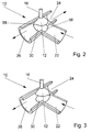
- the distribution channel 30 extends transversely to an axis of rotation 20 of the Throttle body 12 and is on a substantially to the axis of rotation 20 parallel lateral surface 56 open while he at the opposite lateral surface 58 is closed.
- the throttle body 12 can also be a core made of a metallic Have material that e.g. manufactured in the die casting process and has a plastic coating.
- the valve body 14 forms the outer part of the three-way valve 10 and is conveniently injection molded by assembly made of thermoplastic.
- the valve body 14 has a connection 22 for the Internal combustion engine 50 coming part of the feed line 34, a connection 24 for the part leading to the cooler 62 Inlet line 34 and a connection 26 for the bypass line 38.
- the connections 22, 24, 26 are perpendicular in one plane to the axis of rotation 20. You are in a simple manner by insert parts molded in the injection mold.
- the valve body 14 in the embodiment according to FIG. 4 towards the throttle body 12 separate sealing rings 32, which are preferably made of tetrafluoroethylene exist and at the same time as storage for the throttle body 12 serve.
- the sealing ring 32 is in the area of Port 26 held by a sleeve 40 which on a End face 44 abuts the sealing ring 32.
- the sleeve 40 will again by a coil spring 28, which is located on a contact surface 46 is supported on the valve body 14, on the sealing ring 32 pressed.
- Fig. 2 and Fig. 3 show the principle of action of a side flow Three-way valve 10.
- the throttle body When the throttle body is in position 12 in Fig. 2, the maximum flow is achieved by the connection 22 through which the coolant flows, both with the connection 24 to the cooler 62 as well as with the connection 26 is connected to the bypass line 38.
- the connection 24 to the cooler 62 When the The throttle body 12 in FIG. 3 is the connection 24 to the cooler 62 blocked and the entire coolant flow is via the bypass line 38 headed. Intermediate positions are also possible so that the coolant flow arbitrarily on a circuit branch via the cooler 62 and a circuit branch via the bypass line 38 according to an associated map can be divided.
Landscapes
- Engineering & Computer Science (AREA)
- General Engineering & Computer Science (AREA)
- Mechanical Engineering (AREA)
- Physics & Mathematics (AREA)
- General Physics & Mathematics (AREA)
- Automation & Control Theory (AREA)
- Chemical & Material Sciences (AREA)
- Combustion & Propulsion (AREA)
- Control Of Throttle Valves Provided In The Intake System Or In The Exhaust System (AREA)
- Temperature-Responsive Valves (AREA)
- Injection Moulding Of Plastics Or The Like (AREA)
Applications Claiming Priority (2)
| Application Number | Priority Date | Filing Date | Title |
|---|---|---|---|
| DE1999160931 DE19960931A1 (de) | 1999-12-17 | 1999-12-17 | Dreiwegeventil |
| DE19960931 | 1999-12-17 |
Publications (2)
| Publication Number | Publication Date |
|---|---|
| EP1108867A2 true EP1108867A2 (fr) | 2001-06-20 |
| EP1108867A3 EP1108867A3 (fr) | 2003-01-29 |
Family
ID=7933050
Family Applications (1)
| Application Number | Title | Priority Date | Filing Date |
|---|---|---|---|
| EP00126745A Withdrawn EP1108867A3 (fr) | 1999-12-17 | 2000-12-06 | Soupape à trois voies |
Country Status (2)
| Country | Link |
|---|---|
| EP (1) | EP1108867A3 (fr) |
| DE (1) | DE19960931A1 (fr) |
Cited By (14)
| Publication number | Priority date | Publication date | Assignee | Title |
|---|---|---|---|---|
| WO2003042517A1 (fr) * | 2001-11-10 | 2003-05-22 | Robert Bosch Gmbh | Soupape pourvue d'un fonctionnement d'urgence |
| EP1529937A1 (fr) * | 2003-11-06 | 2005-05-11 | ITW Automotive Products GmbH & Co. KG | Système de refroidissement pour des moteurs à combustion interne, notamment pour véhicules automobiles |
| EP1881246A3 (fr) * | 2006-07-17 | 2008-01-30 | MHA Zentgraf Merziger Hochdruck Armaturen GmbH & Co. KG | Distributeur pour la distribution de fluide |
| DE102006038213A1 (de) * | 2006-08-16 | 2008-02-21 | Itw Automotive Products Gmbh & Co. Kg | Thermostatventil |
| WO2008151462A1 (fr) * | 2007-06-11 | 2008-12-18 | Guosheng Liang | Régulateur de température pour moteur à combustion interne |
| EP2799685A2 (fr) | 2013-05-03 | 2014-11-05 | Behr Thermot-tronik GmbH | Soupape à entraînement électrique destinée au réglage des débits volumiques dans un système de chauffage et/ou de refroidissement d'un véhicule automobile |
| CN104685275A (zh) * | 2012-07-11 | 2015-06-03 | 伊利诺斯工具制品有限公司 | 恒温阀 |
| EP2647805A3 (fr) * | 2012-04-04 | 2015-11-25 | Behr Thermot-tronik GmbH | Vanne thermostatique pour un moteur à combustion interne |
| WO2016037921A1 (fr) * | 2014-09-12 | 2016-03-17 | Mahle International Gmbh | Vanne de régulation de débits volumétriques |
| US9429064B2 (en) | 2011-09-22 | 2016-08-30 | Mikuni Corporation | Coolant control valve apparatus |
| WO2017034456A1 (fr) * | 2015-08-25 | 2017-03-02 | Scania Cv Ab | Dispositif thermostatique |
| EP3730821A1 (fr) * | 2019-04-23 | 2020-10-28 | Vitesco Technologies GmbH | Vanne multi-voies |
| WO2020145921A3 (fr) * | 2019-01-10 | 2020-11-12 | Kirpart Otomotiv Parcalari Sanayi Ve Ticaret A.S | Module de gestion thermique intelligent pour refroidissement de moteur |
| US20230341062A1 (en) * | 2022-04-25 | 2023-10-26 | Delta Electronics, Inc. | Ball valve |
Families Citing this family (9)
| Publication number | Priority date | Publication date | Assignee | Title |
|---|---|---|---|---|
| DE10127711B4 (de) * | 2001-06-07 | 2007-02-01 | Robert Bosch Gmbh | Dreiwegeventil |
| DE20304623U1 (de) | 2003-03-22 | 2003-06-12 | FESTO AG & Co., 73734 Esslingen | Drehschieberventil |
| DE10345614A1 (de) | 2003-09-29 | 2005-05-12 | Bosch Gmbh Robert | Dreiwegeventil |
| DE102005046117B4 (de) * | 2005-09-27 | 2015-06-25 | Robert Bosch Gmbh | Mehrwegeventil für einen Kühlmittelkreislauf einer Verbrennungskraftmaschine |
| DE102009009854B4 (de) | 2009-02-20 | 2012-05-24 | Audi Ag | Kühlmittelkreislauf für eine Brennkraftmaschine |
| DE102009025351B4 (de) * | 2009-06-18 | 2015-06-11 | Schaeffler Technologies AG & Co. KG | Regelventil zur Regelung eines Kühlmittelkreislaufs einer Verbrennungskraftmaschine |
| DE102011003430B3 (de) | 2011-02-01 | 2012-05-31 | Continental Automotive Gmbh | Verfahren und Vorrichtung zum Überprüfen einer Steuereinrichtung |
| DE102017117680B4 (de) | 2017-08-03 | 2019-06-27 | M + S Armaturen Gmbh | Umschaltventil |
| DE102017130226A1 (de) | 2017-12-15 | 2019-06-19 | BorgWarner Esslingen GmbH | Steuervorrichtung für ein Fluid und Verfahren zu dessen Herstellung |
Citations (1)
| Publication number | Priority date | Publication date | Assignee | Title |
|---|---|---|---|---|
| DE4109498A1 (de) | 1991-03-22 | 1992-09-24 | Bosch Gmbh Robert | Vorrichtung und verfahren zur regelung der temperatur einer brennkraftmaschine |
Family Cites Families (4)
| Publication number | Priority date | Publication date | Assignee | Title |
|---|---|---|---|---|
| FR2388994A1 (fr) * | 1977-04-29 | 1978-11-24 | Sev Marchal | Dispositif de regulation de la temperature du liquide de refroidissement pour moteur a combustion interne |
| DE69325044T2 (de) * | 1992-02-19 | 1999-09-30 | Honda Giken Kogyo K.K., Tokio/Tokyo | Maschinenkühlanlage |
| JP3644262B2 (ja) * | 1998-07-29 | 2005-04-27 | 株式会社デンソー | 液冷式内燃機関の冷却装置 |
| DE10016405A1 (de) * | 2000-04-01 | 2001-10-11 | Bosch Gmbh Robert | Kühlkreislauf |
-
1999
- 1999-12-17 DE DE1999160931 patent/DE19960931A1/de not_active Ceased
-
2000
- 2000-12-06 EP EP00126745A patent/EP1108867A3/fr not_active Withdrawn
Patent Citations (1)
| Publication number | Priority date | Publication date | Assignee | Title |
|---|---|---|---|---|
| DE4109498A1 (de) | 1991-03-22 | 1992-09-24 | Bosch Gmbh Robert | Vorrichtung und verfahren zur regelung der temperatur einer brennkraftmaschine |
Cited By (26)
| Publication number | Priority date | Publication date | Assignee | Title |
|---|---|---|---|---|
| WO2003042517A1 (fr) * | 2001-11-10 | 2003-05-22 | Robert Bosch Gmbh | Soupape pourvue d'un fonctionnement d'urgence |
| EP1529937A1 (fr) * | 2003-11-06 | 2005-05-11 | ITW Automotive Products GmbH & Co. KG | Système de refroidissement pour des moteurs à combustion interne, notamment pour véhicules automobiles |
| EP1881246A3 (fr) * | 2006-07-17 | 2008-01-30 | MHA Zentgraf Merziger Hochdruck Armaturen GmbH & Co. KG | Distributeur pour la distribution de fluide |
| DE102006038213A1 (de) * | 2006-08-16 | 2008-02-21 | Itw Automotive Products Gmbh & Co. Kg | Thermostatventil |
| WO2008020282A3 (fr) * | 2006-08-16 | 2008-05-08 | Itw Automotive Prod Gmbh & Co | Soupape de thermostat |
| DE102006038213B4 (de) * | 2006-08-16 | 2010-11-11 | Itw Automotive Products Gmbh & Co. Kg | Thermostatventil |
| CN101484738B (zh) * | 2006-08-16 | 2011-05-25 | Itw汽车产品有限两合公司 | 温控阀 |
| US7963455B2 (en) | 2006-08-16 | 2011-06-21 | Itw Automotive Products Gmbh & Co. Kg | Thermostat valve |
| WO2008151462A1 (fr) * | 2007-06-11 | 2008-12-18 | Guosheng Liang | Régulateur de température pour moteur à combustion interne |
| US9429064B2 (en) | 2011-09-22 | 2016-08-30 | Mikuni Corporation | Coolant control valve apparatus |
| EP2647805A3 (fr) * | 2012-04-04 | 2015-11-25 | Behr Thermot-tronik GmbH | Vanne thermostatique pour un moteur à combustion interne |
| US9951878B2 (en) | 2012-07-11 | 2018-04-24 | Illinois Tool Works Inc. | Thermostat valve |
| CN104685275A (zh) * | 2012-07-11 | 2015-06-03 | 伊利诺斯工具制品有限公司 | 恒温阀 |
| EP2799685A2 (fr) | 2013-05-03 | 2014-11-05 | Behr Thermot-tronik GmbH | Soupape à entraînement électrique destinée au réglage des débits volumiques dans un système de chauffage et/ou de refroidissement d'un véhicule automobile |
| DE102013208193A1 (de) | 2013-05-03 | 2014-11-06 | Behr Thermot-Tronik Gmbh | Elektrisch antreibbares Ventil für eine Regelung von Volumenströmen in einem Heiz- und/oder Kühlsystem eines Kraftfahrzeuges |
| DE102014218386A1 (de) | 2014-09-12 | 2016-03-17 | Mahle International Gmbh | Ventil für eine Regelung von Volumenströmen |
| WO2016037921A1 (fr) * | 2014-09-12 | 2016-03-17 | Mahle International Gmbh | Vanne de régulation de débits volumétriques |
| WO2017034456A1 (fr) * | 2015-08-25 | 2017-03-02 | Scania Cv Ab | Dispositif thermostatique |
| WO2020145921A3 (fr) * | 2019-01-10 | 2020-11-12 | Kirpart Otomotiv Parcalari Sanayi Ve Ticaret A.S | Module de gestion thermique intelligent pour refroidissement de moteur |
| EP3730821A1 (fr) * | 2019-04-23 | 2020-10-28 | Vitesco Technologies GmbH | Vanne multi-voies |
| WO2020216610A1 (fr) * | 2019-04-23 | 2020-10-29 | Vitesco Technologies GmbH | Distributeur multivoie |
| CN113710938A (zh) * | 2019-04-23 | 2021-11-26 | 纬湃技术有限公司 | 多通阀 |
| CN113710938B (zh) * | 2019-04-23 | 2023-10-24 | 纬湃技术有限公司 | 多通阀 |
| US11885255B2 (en) | 2019-04-23 | 2024-01-30 | Vitesco Technologies GmbH | Multiport valve |
| US20230341062A1 (en) * | 2022-04-25 | 2023-10-26 | Delta Electronics, Inc. | Ball valve |
| US12140244B2 (en) * | 2022-04-25 | 2024-11-12 | Delta Electronics, Inc. | Ball valve |
Also Published As
| Publication number | Publication date |
|---|---|
| EP1108867A3 (fr) | 2003-01-29 |
| DE19960931A1 (de) | 2001-06-28 |
Similar Documents
| Publication | Publication Date | Title |
|---|---|---|
| EP1108867A2 (fr) | Soupape à trois voies | |
| DE60127465T2 (de) | Schleifmittelstrombearbeitungsvorrichtung und -verfahren | |
| DE69817213T2 (de) | Thermostatventil | |
| EP1272747B1 (fr) | Circuit de refroidissement | |
| DE102008006179A1 (de) | Steuerventil für eine Vorrichtung zur variablen Einstellung der Steuerzeiten von Gaswechselventilen in Brennkraftmaschinen | |
| DE102006053310A1 (de) | Ventil zur Steuerung von Volumenströmen | |
| DE102009025341A1 (de) | Regelventil | |
| DE2211046B2 (de) | Regeleinrichtung für einen mit einem Strömungssystem verbundenen Wärmetauscher, insbesondere für einen Heizkörper | |
| EP2992255B1 (fr) | Soupape à entraînement électrique pour régulation de débit volumique dans un système de chauffage ou de refroidissement pour un véhicule automobile | |
| WO2016037921A1 (fr) | Vanne de régulation de débits volumétriques | |
| DE10127711B4 (de) | Dreiwegeventil | |
| DE69829374T2 (de) | Verfahren und vorrichtung für eine umwälzpumpe | |
| EP0165395B1 (fr) | Soupape de régulation pour le circuit du fluide réfrigérant d'un moteur à combustion interne | |
| DE102005026685A1 (de) | Einlasskrümmer und Verfahren zu dessen Herstellung | |
| DE1255969B (de) | Vorrichtung zum Regeln des Druckes einer Fluessigkeit in einer Steuerleitung | |
| DE2448383C2 (de) | Temperaturgesteuertes Ventil | |
| DE2320260A1 (de) | Foerderbegrenzungsventil fuer kuehleinrichtungen | |
| EP1519090A1 (fr) | Soupape à trois voies | |
| DE4329164C2 (de) | Hydraulischer Steuerventilblock | |
| WO1996003586A1 (fr) | Dispositif de commande de positionnement, notamment pour machine-outil | |
| DE3532591A1 (de) | Hydraulische vorrichtung, insbesondere 2-wege-proportionaldrosselventil | |
| DE10335743A1 (de) | Steuerventil, insbesondere für einen Kühlkreislauf | |
| EP1045120A1 (fr) | Agencement d'une soupape pour commander et maintenir une pression | |
| DE3538643A1 (de) | Einrichtung zur drucksteuerung eines hydrostatischen antriebes | |
| DE19858860B4 (de) | Ventil für einen Wärmeträgermediumkreislauf eines Kraftfahrzeuges |
Legal Events
| Date | Code | Title | Description |
|---|---|---|---|
| PUAI | Public reference made under article 153(3) epc to a published international application that has entered the european phase |
Free format text: ORIGINAL CODE: 0009012 |
|
| AK | Designated contracting states |
Kind code of ref document: A2 Designated state(s): AT BE CH CY DE DK ES FI FR GB GR IE IT LI LU MC NL PT SE TR |
|
| AX | Request for extension of the european patent |
Free format text: AL;LT;LV;MK;RO;SI |
|
| PUAL | Search report despatched |
Free format text: ORIGINAL CODE: 0009013 |
|
| AK | Designated contracting states |
Designated state(s): AT BE CH CY DE DK ES FI FR GB GR IE IT LI LU MC NL PT SE TR |
|
| AX | Request for extension of the european patent |
Extension state: AL LT LV MK RO SI |
|
| AKX | Designation fees paid | ||
| REG | Reference to a national code |
Ref country code: DE Ref legal event code: 8566 |
|
| STAA | Information on the status of an ep patent application or granted ep patent |
Free format text: STATUS: THE APPLICATION IS DEEMED TO BE WITHDRAWN |
|
| 18D | Application deemed to be withdrawn |
Effective date: 20030730 |