EP1108876B1 - Moteur à combustion interne - Google Patents
Moteur à combustion interne Download PDFInfo
- Publication number
- EP1108876B1 EP1108876B1 EP00101967A EP00101967A EP1108876B1 EP 1108876 B1 EP1108876 B1 EP 1108876B1 EP 00101967 A EP00101967 A EP 00101967A EP 00101967 A EP00101967 A EP 00101967A EP 1108876 B1 EP1108876 B1 EP 1108876B1
- Authority
- EP
- European Patent Office
- Prior art keywords
- injection
- fuel
- temperature
- exhaust gas
- internal combustion
- Prior art date
- Legal status (The legal status is an assumption and is not a legal conclusion. Google has not performed a legal analysis and makes no representation as to the accuracy of the status listed.)
- Expired - Lifetime
Links
Images








Classifications
-
- F—MECHANICAL ENGINEERING; LIGHTING; HEATING; WEAPONS; BLASTING
- F02—COMBUSTION ENGINES; HOT-GAS OR COMBUSTION-PRODUCT ENGINE PLANTS
- F02D—CONTROLLING COMBUSTION ENGINES
- F02D41/00—Electrical control of supply of combustible mixture or its constituents
- F02D41/0025—Controlling engines characterised by use of non-liquid fuels, pluralities of fuels, or non-fuel substances added to the combustible mixtures
- F02D41/0047—Controlling exhaust gas recirculation [EGR]
- F02D41/005—Controlling exhaust gas recirculation [EGR] according to engine operating conditions
-
- F—MECHANICAL ENGINEERING; LIGHTING; HEATING; WEAPONS; BLASTING
- F02—COMBUSTION ENGINES; HOT-GAS OR COMBUSTION-PRODUCT ENGINE PLANTS
- F02D—CONTROLLING COMBUSTION ENGINES
- F02D41/00—Electrical control of supply of combustible mixture or its constituents
- F02D41/02—Circuit arrangements for generating control signals
- F02D41/021—Introducing corrections for particular conditions exterior to the engine
- F02D41/0235—Introducing corrections for particular conditions exterior to the engine in relation with the state of the exhaust gas treating apparatus
- F02D41/024—Introducing corrections for particular conditions exterior to the engine in relation with the state of the exhaust gas treating apparatus to increase temperature of the exhaust gas treating apparatus
-
- F—MECHANICAL ENGINEERING; LIGHTING; HEATING; WEAPONS; BLASTING
- F02—COMBUSTION ENGINES; HOT-GAS OR COMBUSTION-PRODUCT ENGINE PLANTS
- F02D—CONTROLLING COMBUSTION ENGINES
- F02D41/00—Electrical control of supply of combustible mixture or its constituents
- F02D41/30—Controlling fuel injection
- F02D41/38—Controlling fuel injection of the high pressure type
- F02D41/40—Controlling fuel injection of the high pressure type with means for controlling injection timing or duration
- F02D41/402—Multiple injections
-
- F—MECHANICAL ENGINEERING; LIGHTING; HEATING; WEAPONS; BLASTING
- F01—MACHINES OR ENGINES IN GENERAL; ENGINE PLANTS IN GENERAL; STEAM ENGINES
- F01N—GAS-FLOW SILENCERS OR EXHAUST APPARATUS FOR MACHINES OR ENGINES IN GENERAL; GAS-FLOW SILENCERS OR EXHAUST APPARATUS FOR INTERNAL-COMBUSTION ENGINES
- F01N2430/00—Influencing exhaust purification, e.g. starting of catalytic reaction, filter regeneration, or the like, by controlling engine operating characteristics
-
- F—MECHANICAL ENGINEERING; LIGHTING; HEATING; WEAPONS; BLASTING
- F02—COMBUSTION ENGINES; HOT-GAS OR COMBUSTION-PRODUCT ENGINE PLANTS
- F02B—INTERNAL-COMBUSTION PISTON ENGINES; COMBUSTION ENGINES IN GENERAL
- F02B3/00—Engines characterised by air compression and subsequent fuel addition
- F02B3/06—Engines characterised by air compression and subsequent fuel addition with compression ignition
-
- F—MECHANICAL ENGINEERING; LIGHTING; HEATING; WEAPONS; BLASTING
- F02—COMBUSTION ENGINES; HOT-GAS OR COMBUSTION-PRODUCT ENGINE PLANTS
- F02D—CONTROLLING COMBUSTION ENGINES
- F02D41/00—Electrical control of supply of combustible mixture or its constituents
- F02D41/02—Circuit arrangements for generating control signals
- F02D41/021—Introducing corrections for particular conditions exterior to the engine
- F02D41/0235—Introducing corrections for particular conditions exterior to the engine in relation with the state of the exhaust gas treating apparatus
- F02D41/027—Introducing corrections for particular conditions exterior to the engine in relation with the state of the exhaust gas treating apparatus to purge or regenerate the exhaust gas treating apparatus
- F02D41/0275—Introducing corrections for particular conditions exterior to the engine in relation with the state of the exhaust gas treating apparatus to purge or regenerate the exhaust gas treating apparatus the exhaust gas treating apparatus being a NOx trap or adsorbent
- F02D41/028—Desulfurisation of NOx traps or adsorbent
-
- F—MECHANICAL ENGINEERING; LIGHTING; HEATING; WEAPONS; BLASTING
- F02—COMBUSTION ENGINES; HOT-GAS OR COMBUSTION-PRODUCT ENGINE PLANTS
- F02D—CONTROLLING COMBUSTION ENGINES
- F02D41/00—Electrical control of supply of combustible mixture or its constituents
- F02D41/02—Circuit arrangements for generating control signals
- F02D41/021—Introducing corrections for particular conditions exterior to the engine
- F02D41/0235—Introducing corrections for particular conditions exterior to the engine in relation with the state of the exhaust gas treating apparatus
- F02D41/027—Introducing corrections for particular conditions exterior to the engine in relation with the state of the exhaust gas treating apparatus to purge or regenerate the exhaust gas treating apparatus
- F02D41/029—Introducing corrections for particular conditions exterior to the engine in relation with the state of the exhaust gas treating apparatus to purge or regenerate the exhaust gas treating apparatus the exhaust gas treating apparatus being a particulate filter
-
- F—MECHANICAL ENGINEERING; LIGHTING; HEATING; WEAPONS; BLASTING
- F02—COMBUSTION ENGINES; HOT-GAS OR COMBUSTION-PRODUCT ENGINE PLANTS
- F02M—SUPPLYING COMBUSTION ENGINES IN GENERAL WITH COMBUSTIBLE MIXTURES OR CONSTITUENTS THEREOF
- F02M26/00—Engine-pertinent apparatus for adding exhaust gases to combustion-air, main fuel or fuel-air mixture, e.g. by exhaust gas recirculation [EGR] systems
- F02M2026/001—Arrangements; Control features; Details
- F02M2026/009—EGR combined with means to change air/fuel ratio, ignition timing, charge swirl in the cylinder
-
- F—MECHANICAL ENGINEERING; LIGHTING; HEATING; WEAPONS; BLASTING
- F02—COMBUSTION ENGINES; HOT-GAS OR COMBUSTION-PRODUCT ENGINE PLANTS
- F02M—SUPPLYING COMBUSTION ENGINES IN GENERAL WITH COMBUSTIBLE MIXTURES OR CONSTITUENTS THEREOF
- F02M26/00—Engine-pertinent apparatus for adding exhaust gases to combustion-air, main fuel or fuel-air mixture, e.g. by exhaust gas recirculation [EGR] systems
- F02M26/02—EGR systems specially adapted for supercharged engines
- F02M26/04—EGR systems specially adapted for supercharged engines with a single turbocharger
- F02M26/05—High pressure loops, i.e. wherein recirculated exhaust gas is taken out from the exhaust system upstream of the turbine and reintroduced into the intake system downstream of the compressor
-
- F—MECHANICAL ENGINEERING; LIGHTING; HEATING; WEAPONS; BLASTING
- F02—COMBUSTION ENGINES; HOT-GAS OR COMBUSTION-PRODUCT ENGINE PLANTS
- F02M—SUPPLYING COMBUSTION ENGINES IN GENERAL WITH COMBUSTIBLE MIXTURES OR CONSTITUENTS THEREOF
- F02M26/00—Engine-pertinent apparatus for adding exhaust gases to combustion-air, main fuel or fuel-air mixture, e.g. by exhaust gas recirculation [EGR] systems
- F02M26/02—EGR systems specially adapted for supercharged engines
- F02M26/09—Constructional details, e.g. structural combinations of EGR systems and supercharger systems; Arrangement of the EGR and supercharger systems with respect to the engine
- F02M26/10—Constructional details, e.g. structural combinations of EGR systems and supercharger systems; Arrangement of the EGR and supercharger systems with respect to the engine having means to increase the pressure difference between the exhaust and intake system, e.g. venturis, variable geometry turbines, check valves using pressure pulsations or throttles in the air intake or exhaust system
-
- Y—GENERAL TAGGING OF NEW TECHNOLOGICAL DEVELOPMENTS; GENERAL TAGGING OF CROSS-SECTIONAL TECHNOLOGIES SPANNING OVER SEVERAL SECTIONS OF THE IPC; TECHNICAL SUBJECTS COVERED BY FORMER USPC CROSS-REFERENCE ART COLLECTIONS [XRACs] AND DIGESTS
- Y02—TECHNOLOGIES OR APPLICATIONS FOR MITIGATION OR ADAPTATION AGAINST CLIMATE CHANGE
- Y02T—CLIMATE CHANGE MITIGATION TECHNOLOGIES RELATED TO TRANSPORTATION
- Y02T10/00—Road transport of goods or passengers
- Y02T10/10—Internal combustion engine [ICE] based vehicles
- Y02T10/12—Improving ICE efficiencies
-
- Y—GENERAL TAGGING OF NEW TECHNOLOGICAL DEVELOPMENTS; GENERAL TAGGING OF CROSS-SECTIONAL TECHNOLOGIES SPANNING OVER SEVERAL SECTIONS OF THE IPC; TECHNICAL SUBJECTS COVERED BY FORMER USPC CROSS-REFERENCE ART COLLECTIONS [XRACs] AND DIGESTS
- Y02—TECHNOLOGIES OR APPLICATIONS FOR MITIGATION OR ADAPTATION AGAINST CLIMATE CHANGE
- Y02T—CLIMATE CHANGE MITIGATION TECHNOLOGIES RELATED TO TRANSPORTATION
- Y02T10/00—Road transport of goods or passengers
- Y02T10/10—Internal combustion engine [ICE] based vehicles
- Y02T10/40—Engine management systems
Definitions
- the present invention relates to an internal combustion engine.
- an NO x absorbent which absorbs the NO x in exhaust gas when the air-fuel ratio of the exhaust gas is lean and releases and reduces the absorbed NO x when the air-fuel ratio of the exhaust gas becomes the stoichiometric air-fuel ratio or rich.
- the air-fuel ratio of the exhaust gas is temporarily made rich before the NO x absorption capability of the NO x absorbent becomes saturated so as to make all of the NO x absorbed in the NO x absorbent be released from the NO x absorbent and reduced.
- the exhaust gas contains SO x .
- This SO x is also absorbed by the NO x absorbent.
- This SO x is not released from the NO x absorbent just by making the air-fuel ratio of the exhaust gas rich.
- To make the SO x be released from the NO x absorbent it is necessary to raise the temperature of the NO x absorbent. Therefore, there is known an internal combustion engine wherein when the temperature of the NO x absorbent should be raised, additional fuel is injected in the expansion stroke or exhaust stroke in addition to the main fuel injected during the suction stroke and that additional fuel is made to burn in the NO x absorbent so as to raise the temperature of the NO x absorbent (see Japanese Unexamined Patent Publication (Kokai) No. 9-32619).
- An object of the present invention is to provide an internal combustion engine capable of raising a temperature of an exhaust gas after-treatment device at a temperature raising rate which is required for the exhaust gas after-treatment device.
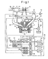
- FIG. 1 shows an engine body, 2 a cylinder block, 3 a cylinder head, 4 a piston, 5 a combustion chamber, 6 an electrically controlled fuel injector, 7 an intake valve, 8 an intake port, 9 an exhaust valve, and 10 an exhaust port.
- the intake port 8 is connected through a corresponding intake tube 11 to a surge tank 12.
- the surge tank 12 is connected through an intake duct 13 to a compressor 15 of an exhaust turbocharger 14.
- a throttle valve 17 driven by a step motor 16 is arranged in the intake duct 13.
- the exhaust port 10 is connected through an exhaust manifold 18 and exhaust tube 19 to an exhaust turbine 20 of the exhaust turbocharger 14.
- the outlet of the exhaust turbine 20 is connected to an exhaust gas after-treatment device 21.
- the exhaust gas after-treatment device 21 is comprised of an NO x absorbent 22 and a casing 23 housing the NO x absorbent 22.
- the exhaust manifold 18 and the surge tank 12 are connected to each other through an exhaust gas recirculation (EGR) passage 24.
- An EGR control valve 25 is arranged in the EGR passage 24.
- Each fuel injector 6 is connected through a fuel supply line 26 to a fuel reservoir, that is, a so-called common rail 27. Fuel is supplied into this common rail 27 from an electronically controlled variable discharge fuel pump 28. The fuel supplied into the common rail 27 is supplied through the fuel supply lines 26 to the fuel injectors 6.
- the common rail 27 has mounted in it a fuel pressure sensor for detecting the fuel pressure in the common rail 27. The amount of discharge of the fuel pump 28 is controlled based on the output signal of the fuel pressure sensor 29 so that the fuel pressure in the common rail 27 becomes a target fuel pressure.
- the electronic control unit 30 is comprised of a digital computer and is provided with a read only memory (ROM) 32, a random access memory (RAM) 33, a microprocessor (CPU) 34, an input port 35, and an output port 36 connected with each other by a bidirectional bus 31.
- ROM read only memory
- RAM random access memory
- CPU microprocessor
- input port 35 Downstream of the NO x absorbent 22 is arranged a temperature sensor 39 for detecting the temperature of the NO x absorbent 22.
- the output signals of the temperature sensor 39 and the fuel pressure sensor 29 are input through corresponding A/D converters 37 to the input port 35.
- the accelerator pedal 40 has connected to it a load sensor 41 for generating an output voltage proportional to the amount of depression of the accelerator pedal 40.
- the output voltage of the load sensor 41 is input through a corresponding AD converter 37 to the input port 35.
- the input port 35 has connected to it a crank angle sensor 42 for generating an output pulse every time the crank shaft rotates by for example 30 degrees.
- the output port 36 has connected to it through corresponding drive circuits 38 the fuel injectors 6, step motor 16, EGR control valve 25, and fuel pump 28.
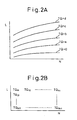
- the required torques TQ shown in Fig. 2A are stored in the ROM 32 in advance in the form of a map as a function of the amount of depression L of the accelerator pedal 40 and the engine rotational speed N as shown in Fig. 2B.
- the required torque TG is first calculated in accordance with the amount of depression L of the accelerator pedal 40 and the engine rotational speed N from the map shown in Fig. 2B and then the amount of fuel injection etc. are calculated based on the required torque TQ.
- Figure 3 shows the amount of injection Q at the time of ordinary operation, the injection start timing ⁇ S, the degree of opening ST of the throttle valve 17, the degree of opening SE of the EGR control valve 25, the mean air-fuel ratio A/F of the air-fuel mixture in the combustion chamber 5, and the EGR rate (amount of EGR gas/(amount of intake air + amount of EGR gas). Note that in Fig. 3, the abscissa shows the required torque TQ.
- the injection start timing ⁇ S is made before top dead center of the compression stroke.
- the EGR rate falls the higher the required torque TQ.
- the ER rate becomes zero in the region of the high required torque TQ.
- the degree of opening ST of the throttle valve 17 and the degree of opening SE of the EGR control valve 25 are made to change so that the EGR rate changes as explained above. That is, the degree of opening ST of the throttle valve 17 is made to increase as the required torque TQ becomes higher in the region of a low required torque TQ.
- the throttle valve 17 is made to fully open when the required torque TQ becomes further higher.
- the EGR valve 25 is made to fully open in the region of a low required torque TQ and made to completely close in the region of a high required torque TQ. Between the region of the low required torque TQ and the region of the high required torque TQ, the degree of opening SE of the EGR valve 25 is gradually reduced as the required torque TQ becomes higher. Further, it is made smaller when the mean air-fuel ratio A/F in the combustion chamber 5 is lean and the required torque TQ becomes higher.
- the amount of injection Q, the injection start timing ⁇ S, the degree of opening ST of the throttle valve 17, and the degree of opening SE of the EGR control valve 25 are not functions of just the required torque TQ, but are functions of the required torque TQ and the engine rotational speed N.
- the amount of injection Q is stored in advance in the ROM 32 in the form of a map as a function of the required torque TQ and the engine rotational speed N.
- the injection start timing ⁇ S is also stored in advance in the ROM 32 in the form of a map as a function of the required torque TQ and the engine rotational speed N.
- the NO x absorbent 22 housed in the casing 23 in Fig. 1 is comprised of for example alumina as a carrier and, carried on that carrier, for example, at least one element selected from potassium K, sodium Na, lithium Li, cesium Cs, and other alkali metals, barium Ba, calcium Ca and other alkali earth metals, and lanthanum La, yttrium Y, and other rare earths plus a rare metal such as platinum.
- the NO x absorbent 22 performs an NO x absorption and release action in which it absorbs NO x when the air-fuel ratio of the inflowing exhaust gas is lean while releases the absorbed NO x when the air-fuel ratio of the inflowing exhaust gas becomes the stoichiometric air-fuel ratio or rich.
- this NO x absorbent 22 will in actuality perform an NO x absorption and release action, but there are portions of the detailed mechanism of this absorption and release action which are still not clear.
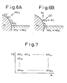
- This absorption and release action is considered to be performed by the mechanism shown in Figs. 6A and 6B.
- this mechanism will be explained taking as an example the case of carrying platinum Pt and barium Ba on the carrier, but the same mechanism applies even if using another precious metal and alkali metal, alkali earth, or rare earth.
- combustion is performed when the mean air-fuel ratio in the combustion chamber 5 is in a lean state.
- the concentration of oxygen in the exhaust gas is high.
- the oxygen O 2 deposits on the surface of the platinum Pt in the form of O 2 - or O 2- .
- the NO in the inflowing exhaust gas reacts with the O 2 - or O 2- on the surface of the platinum Pt to become NO 2 (2NO+O 2 ⁇ 2NO 2 ).
- part of the produced NO 2 is oxidized on the platinum Pt and absorbed in the absorbent and diffuses inside the absorbent in the form of nitrate ions NO 3 - as shown in Fig. 6A while bonding with the barium oxide BaO.
- the NO x is absorbed in the NO x absorbent 22 in this way. So long as the concentration of oxygen in the inflowing exhaust gas is high, NO 2 is produced on the surface of the platinum Pt. So long as the NO x absorption capability of the absorbent does not become saturated, the NO 2 is absorbed in the absorbent and nitrate ions NO 3 - are produced.
- the concentration of oxygen in the inflowing exhaust gas falls and as a result the amount of production of NO 2 on the surface of the platinum Pt falls. If the amount of production of NO 2 falls, the reaction proceeds in the reverse direction (NO 3 - ⁇ NO 2 ) and therefore the nitrate ions NO 3 - in the absorbent are released from the absorbent in the form of NO 2 . At this time, the NO x released from the NO x absorbent 22 reacts with the large amount of unburnt hydrocarbons and carbon monoxide contained in the inflowing exhaust gas to be reduced as shown in Fig. 6B.
- the amount of NO x absorption AX per unit time is found in advance in the form of the map shown in Fig. 7 as a function of the required torque TQ and the engine rotational speed N.
- the amount ⁇ NOX of NO x absorbed in the NO x absorbent 22 is estimated by cumulative addition of the amount of NO x absorption AX.
- the air-fuel ratio of the inflowing exhaust gas is temporarily made rich so as to make the NO x be released from the NO x absorbent 22.
- exhaust gas contains SO x and the NO x absorbent 22 absorbs not only NO x , but also SO x .
- the mechanism of absorption of SO x into the NO x absorbent 22 is believed to be the same as the mechanism of absorption of NO x .
- part of the produced SO 3 is oxidized on the platinum Pt and absorbed in the absorbent and diffuses inside the absorbent in the form of sulfate ions SO 4 2 while bonding with the barium oxide BaO to produce the stable sulfate BaSO 4 .
- This sulfate BaSO 4 is stable and hard to decompose. Even if the air-fuel ratio of the inflowing exhaust gas is made rich for release of the NO x from the NO x absorbent 22, the sulfate BaSO 4 does not decompose and remains as it is. Therefore, along with the passage of time, the sulfate BaSO 4 in the NO x absorbent 22 increases and therefore along with time the amount of NO x which the NO x absorbent 22 can absorb falls.
- the sulfate BaSO 4 decomposes when the temperature of the NO x absorbent 22 exceeds a certain temperature determined by the NO x absorbent 22, for example, about 600°C. If the air-fuel ratio of the exhaust gas flowing into the NO x absorbent 22 at this time is made the stoichiometric air-fuel ratio or rich, the SO x will be released from the NO x absorbent 22. Making the SO x be released from the NO x absorbent 22, however, requires a considerably long time compared with the case of releasing the NO x from the NO x absorbent 22.
- the injection timing of the main fuel is delayed so as to raise the temperature of the exhaust gas and auxiliary fuel is injected in addition to the main fuel so as to increase the amount of the unburned hydrocarbons in the exhaust gas.
- Various injection patterns different in at least one of the amount of retardation of the injection timing of the main fuel and the injection timing of the auxiliary fuel are used.
- injection patterns that is, a first pattern of delaying the injection timing of the main fuel without injecting auxiliary fuel, a second pattern of injecting auxiliary fuel before injecting the main fuel and delaying the injection timing of the main fuel, a third pattern of injecting auxiliary fuel before injecting the main fuel and after injecting the main fuel and delaying the injection timing of the main fuel, and a fourth pattern of injecting auxiliary fuel after injecting the main fuel and delaying the injection timing of the main fuel.
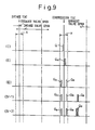
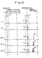
- Figure 8 to Fig. 10 show the injection timings of the main fuel and the injection timings of the auxiliary fuel.
- the abscissas show the crank angle.
- Fig. 8 to Fig. 10 show the opening timings of the intake valve 7, the opening timings of the exhaust valve 9, and the injection timing X in which fuel injected from a fuel injector 6 can be supplied into a cavity 5a (Fig. 1) formed at the top face of the piston 4.
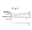
- Fig. 11 shows the injection start timing ⁇ S of the main fuel.
- the abscissa in Fig. 11 shows the required torque TQ.
- FIG. 8 to Fig. 10 shows the injection timing at the time of ordinary operation.
- auxiliary fuel is not injected during ordinary operation. Only main fuel Q is injected.
- the injection start timing ⁇ S of the main fuel Q at this time is shown by I in Fig. 11.
- the injection start timing ⁇ S of the main fuel at this time is made before top dead center of the compression stroke.
- (II) shows the first injection pattern.
- the injection timing of the main fuel Q R is delayed compared with the time of ordinary operation.
- II in Fig. 11 shows the injection start timing ⁇ S of the main fuel Q R at this time.
- the injection start timing ⁇ S of the main fuel Q R at this time is delayed until after top dead center of the compression stroke and is delayed more the higher the required torque TQ.
- the pressure in the combustion chamber 5 gradually falls and the temperature in the combustion chamber 5 also gradually falls. Since the pressure in the combustion chamber 5 gradually falls after the top dead center of the compression stroke in this way, if the injection start timing ⁇ S of the main fuel Q R is delayed until after top dead center of the compression stroke, the injected fuel will be made to widely diffuse inside the combustion chamber 5 and will be ignited after being widely diffused. That is, the fuel will be burned in a state with sufficient air present around it. As a result, soot will not be produced much. Further, at the time of ignition, the pressure and temperature in the combustion chamber 5 become low, therefore the combustion temperature will not rise that much. Accordingly, not that much NO x will be produced either.
- the injection start timing ⁇ S of the main fuel Q R is delayed in this way, the combustion time will become longer and therefore the temperature of the exhaust gas will rise. If the temperature of the exhaust gas rises, the temperature of the exhaust gas after-treatment device 21, in the embodiment shown in Fig. 1, the temperature of the NO x absorbent 22, will be made to rise. In this case, the more the injection start timing ⁇ S of the main fuel Q R is delayed, the higher the temperature of the exhaust gas and therefore, from the viewpoint of raising the temperature of the NO x absorbent 22, it is preferable to delay the injection start timing ⁇ S of the main fuel Q R as much as possible. If the injection start timing ⁇ S of the main fuel QR is delayed too much, however, misfires will occur. Therefore, in the first injection pattern, the injection start timing ⁇ S of the main fuel Q R is set to a timing as much delayed as possible while still in a range where no misfires occur.
- FIG. 8 shows a first example of the second injection pattern.
- auxiliary fuel Q V is injected near top dead center of the suction stroke.
- the injection start timing ⁇ S of the main fuel Q R is further delayed.
- the III of Fig. 11 shows the injection start timing ⁇ S of the main fuel at this time.
- the injection start timing ⁇ S of the main fuel Q R at this time is delayed further from the case of the first injection pattern shown by (II) in Fig. 11. Further, at this time as well, the injection start timing ⁇ S of the main fuel Q R is delayed more the higher the required torque TQ.
- the auxiliary fuel Q V In the vicinity of the top dead center of the suction stroke, almost no suction air has been fed into the combustion chamber 5 and, thus, the unburned gas is maintained at a high temperature. Accordingly, if the auxiliary fuel Q V is injected rear top dead center of the suction stroke, the auxiliary fuel Q V is instantaneously vaporized. If the auxiliary fuel Q V is vaporized, the heat of compression during the compression stroke causes the production of aldehydes, ketones, peroxides, carbon monoxide, and other intermediate products from the auxiliary fuel Q V . These intermediate products cause the reaction of the main fuel Q R to be accelerated.
- auxiliary fuel Q V is injected at the injection timing X where the injected fuel is supplied into the cavity 5a of the piston 4. Therefore, it is possible to prevent the auxiliary fuel Q V from depositing on the inner wall of the cylinder bore. As a result, it is possible to prevent the lubrication oil from being diluted by the injected fuel.
- FIG. 9 shows a second example of the second injection pattern.
- the auxiliary fuel Q e is injected at the end of the compression stroke.
- the injection start timing ⁇ S of the main fuel Q R is further delayed.
- the injection start timing ⁇ S of the main fuel Q R at this time is shown by III in Fig. 11.
- aldehydes, ketones, peroxides, carbon monoxide, and other intermediate products are produced from the auxiliary fuel Q e and these intermediate products cause the reaction of the main fuel Q R to be accelerated. Therefore, in this case as well, even if the injection start timing ⁇ S of the main fuel Q R is delayed by a large extent, good combustion can be secured without causing misfires.
- the second example unlike the first example shown by (III) in Fig. 8, fuel is not injected to positively increase the amount of unburned hydrocarbons in the exhaust gas. That is, the second example is aimed at raising the temperature of the exhaust gas by delaying the injection start timing ⁇ S of the main fuel Q R further from the case of the first injection pattern shown by (II) in Fig. 9. Therefore, compared with the case of the first injection pattern shown by (II) in Fig. 9, the second example has a more powerful action of raising the temperature of the NO x absorbent 22, but compared with the first example, the second example has a weaker action of raising the temperature of the NO x absorbent 22.
- (IV-1) and (IV-2) in Fig. 8 show a first example of the third injection pattern.
- the auxiliary fuel Q V and main fuel Q R are injected at the same timings as the second injection pattern shown by (III) in Fig. 8 and auxiliary fuel Q P is further injected during the expansion stroke or exhaust stroke after injection of the main fuel Q R .
- the auxiliary fuel Q P is injected during the expansion stroke just before the exhaust valve 9 opens.
- the auxiliary fuel Q P is not burned in the combustion chamber 5, therefore if the auxiliary fuel Q P is injected, the auxiliary fuel Q P is exhausted into the exhaust port 10 in the form of unburned hydrocarbons. Therefore, if the auxiliary fuel Q P is injected, the amount of unburned hydrocarbons in the exhaust gas is increased and therefore the heat of oxidation reaction of the unburned hydrocarbons causes the temperature of the NO x absorbent 22 to rapidly rise.
- the number of injections of the auxiliary fuel Q P may be increased. That is, if injecting a large amount of auxiliary fuel Q P , the penetration force of the injected fuel becomes greater, so part of the auxiliary fuel Q P ends up depositing on the inner wall of the cylinder bore. As opposed to this, if the amount of injection of the auxiliary fuel Q P is reduced, the penetration force of the injected fuel becomes smaller, so the auxiliary fuel Q P will no longer deposit on the inner wall of the cylinder bore. Therefore, when increasing the amount of injection of the auxiliary fuel Q P , as shown by (IV-2) in Fig. 8, small amounts of the auxiliary fuel Q P are injected at intervals over several times.
- FIG. 8 shows a second example of the third injection pattern.
- the auxiliary fuel Q e and the main fuel Q R are injected at the same timings as the second injection pattern shown by (III) in Fig. 9 and further auxiliary fuel Q P is injected during the expansion stroke or exhaust stroke after the injection of the main fuel Q R .
- the auxiliary fuel Q P is injected during the expansion stroke right before the exhaust valve 9 opens.
- FIG. 10 shows the fourth injection pattern.
- the main fuel Q R is injected at the same timing as the first injection pattern shown by (II) of Fig. 10 and further auxiliary fuel Q P is injected during the expansion stroke or exhaust stroke after injection of the main fuel QR.
- the auxiliary fuel Q P is injected during the expansion stroke right before the exhaust valve 9 opens.
- the injection pattern is changed in this way, one or both of the temperature of the exhaust gas or the amount of the unburned hydrocarbons in the exhaust gas change, therefore the rate of rise of the temperature of the NO x absorbent 22 changes. Further, even with the same injection pattern, if the number of injections of the auxiliary fuel Q P after top dead center of the compression stroke is changed, the amount of unburned hydrocarbons in the exhaust gas changes and therefore the rate of rise of the temperature of the NO x absorbent 22 changes. Accordingly, by changing the injection pattern or changing the number of injections of the auxiliary fuel Q P after top dead center of the compression stroke, it is possible to control the temperature raising rate of the NO x absorbent 22 to the optimal rate.
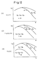
- Figure 12 shows the relationship between the injection pattern used when raising the temperature of the NO x absorbent 22, the required torque TQ, and the engine rotational speed N. That is, the region shown by Q in Fig. 12 shows the operating region where the injection Q of ordinary operation shown by (I) in Fig. 8 is performed, the region shown by Q R shows the operating region where injection is performed by the first injection pattern Q R shown by (II) in Fig. 8, the region shown by Q V +Q R shows the operating region where injection is performed by the second injection pattern Q V +Q R shown by (III) in Fig. 8, and the region shown by Q V +Q R +Q P shows the operating region where injection is performed by the third injection pattern Q V +Q R +Q P shown by (IV-1) or (IV-2) in Fig. 8.
- Fig. 12 shows when the temperature TC of the exhaust gas after-treatment device 21, in this embodiment, the temperature TC of the NO x absorbent 22, is lower than a predetermined first temperature T1, for example 300°C
- a predetermined first temperature T1 for example 300°C
- a predetermined second temperature T2 for example, 500°C
- (3) in Fig. 12 shows when the temperature TC of the NO x absorbent 22 is higher than the second temperature T2.
- injection is performed by the first injection pattern Q R in the limited operating region where the required torque TQ is high and the engine rotational speed N is high, injection is performed by the second injection pattern Q V +Q R in the operating region at the low load side of this operating region, and injection is performed by the third injection pattern Q V +Q R +Q P in the operating region at the further lower load side of this operating region.
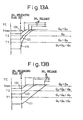
- Figure 13A shows the change in the temperature TC of the NO x absorbent 22 and the change in the injection pattern when assuming the action of raising the temperature of the NO x absorbent 22 is started and the same required torque TQ and engine rotational speed N are maintained after that as well in the case of the required torque TQ and the engine rotational speed N shown by the point A in Fig. 12.
- the solid line (1) in Fig. 13A shows the case where the action of raising the temperature of the NO x absorbent 22 was started when TC ⁇ T1 as shown by (1) in Fig. 12
- the solid line (2) in Fig. 13A shows the case where the action of raising the temperature of the NO x absorbent 22 was started when T1 ⁇ TC ⁇ T2 as shown by (2) in Fig. 12
- the solid line (3) in Fig. 13A shows the case where the action of raising the temperature of the NO x absorbent 22 was started when T2 ⁇ TC as shown by (3) in Fig. 12.
- the action of raising the temperature of the NO x absorbent 22 is started when an SO x releasing flag showing that SO x should be released from the NO x absorbent 22 is set.
- the action of releasing the SO x from the NO x absorbent 22 is started when the temperature TC of the NO x absorbent 22 passes a target temperature T max where the SO x can be released.
- the action of raising the temperature of the NO x absorbent 22 is started when TC ⁇ T1, first injection is performed by the third injection pattern Q V +Q R +Q P , then when TC ⁇ T1, injection is performed by the second injection pattern Q V +Q R , then, when TC ⁇ T2, injection is performed by the first injection pattern Q R .
- the temperature raising rate of the NO x absorbent 22 due to the third injection pattern Q V +Q R +Q P is the highest
- the temperature raising rate of the NO x absorbent 22 due to the second injection pattern Q V +Q R is the next highest
- the temperature raising rate of the NO x absorbent 22 due to the first injection pattern Q R is the lowest.
- Figure 13B shows the change in the temperature TC of the NO x absorbent 22 and the change in the injection pattern when assuming the action of raising the temperature of the NO x absorbent 22 is started and the same required torque TQ and engine rotational speed N are maintained after that as well in the case of the required torque TQ and the engine rotational speed N shown by the point B in Fig. 12.
- the solid line (1) in Fig. 13B shows the case where the action of raising the temperature of the NO x absorbent 22 was started when TC ⁇ T1 as shown by (1) in Fig. 12
- the solid line (2) in Fig. 13B shows the case where the action of raising the temperature of the NO x absorbent 22 was started when T1 ⁇ TC ⁇ T2 as shown by (2) in Fig. 12
- the solid line (3) in Fig. 13B shows the case where the action of raising the temperature of the NO x absorbent 22 was started when T2 ⁇ TC as shown by (3) in Fig. 12.
- the third injection pattern Q V +Q R +Q P is switched to the second injection pattern Q V +Q R , then, when the temperature TC of the NO x absorbent 22 approaches the target temperature T max , that is, when TC ⁇ T2, the second injection pattern Q V +Q R is switched to the first injection pattern Q R . If the first injection pattern Q R is used, the temperature raising rate of the NO x absorbent 22 becomes smaller and therefore the control of the temperature TC of the NO x absorbent 22 becomes easy. Accordingly, it is possible to prevent thermal deterioration of the NO x absorbent 22 and possible to reduce the amount of fuel consumption.
- the temperature TC of the NO x absorbent 22 is first made to rise relatively quickly, then to prevent thermal deterioration of the NO x absorbent 22 and reduce the amount of fuel consumption, the second injection pattern Q V +Q R is switched to the first injection pattern Q R .
- the solid line (3) in Fig. 13A when the action of raising the temperature of the NO x absorbent 22 is started when TC ⁇ T2, injection is performed by the first injection pattern Q R from the start so as to prevent thermal deterioration of the NO x absorbent 22 and reduce the amount of fuel consumption.
- the temperature TC of the NO x absorbent 22 can be easily controlled and consequently there is no risk of the temperature TC of the NO x absorbent 22 become extremely high and of thermal deterioration of the NO x absorbent 22.
- the optimal injection pattern for the temperature TC of the NO x absorbent 22 when raising the temperature TC of the NO x absorbent 22, the optimal injection pattern for the temperature TC of the NO x absorbent 22, the required torque TQ, and the engine rotational speed N is used.
- the injection patterns shown in Fig. 12 are just examples and it is possible to use a fourth injection pattern Q R +Q P in accordance with need.
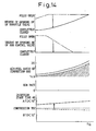
- Figure 14 shows the degree of opening ST of the throttle valve 17, the degree of opening SE of the EGR control valve 25, the air-fuel ratio of the combustion gas of the main fuel in the combustion chamber 5, the EGR rate, and the injection start timing ⁇ S of the main fuel when releasing SO x from the NO x absorbent 22.
- the dash-dot lines show the degrees of opening at the time of ordinary operation shown in Fig. 3 and the solid lines shown the degrees of opening at the time of release of SO x .
- the broken line shows the limit of production of smoke. Smoke is produced in the hatched region.
- the injection start timing ⁇ S of the main fuel shows the timing at the time of ordinary operation and the solid line shows the timing at the time of release of SO x .
- the EGR control valve 25 when SO x is to be released from the NO x absorbent 22, the EGR control valve 25 is completely closed, therefore the EGR rate becomes zero. Further, the injection start timing ⁇ S of the main fuel is delayed to after the top dead center of the compression stroke. At this time, the degree of opening ST of the throttle valve 17 is reduced so that the air-fuel ratio of the combustion gas of the main fuel becomes the target air-fuel ratio shown by the solid line slightly larger than the smoke limit. The target air-fuel ratio of the combustion gas shown by the solid line becomes smaller the lower the required torque TQ, therefore the degree of opening ST of the throttle valve 17 becomes smaller the lower the required torque TQ.
- auxiliary fuel Q P is injected during the expansion stroke or exhaust stroke so that the air-fuel ratio of the exhaust gas flowing into the NO x absorbent 22 becomes the stoichiometric air-fuel ratio or rich.
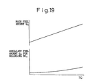
- auxiliary fuel Q P is injected during the expansion stroke right before the exhaust valve 9 opens so that the exhaust gas flowing into the NO x absorbent 22 becomes just slightly rich. That is, when SO x is to be released from the NO x absorbent 22, injection is performed by the fourth injection pattern Q R +Q P shown by (III-1) or (III-2) or (III-3) of Fig. 10. As shown in Fig. 15, when SO x is to be released from the NO x absorbent 22, the amount of the auxiliary fuel Q P increases the higher the required torque TQ.
- the degree of opening ST of the throttle valve 17 and the injection start timing ⁇ S of the main fuel when SO x is to be released from the NO x absorbent 22 are not functions of just the required torque TQ, but are functions of the required torque TQ and the engine rotational speed N.
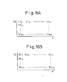
- the degree of opening ST of the throttle valve 17 and the injection start timing ⁇ S of the main fuel when SO x is to be released from the NO x absorbent 22 are stored in advance in the ROM 32 in the form of maps as functions of the required torque TQ and the engine rotational speed N as shown in Fig. 16A and Fig. 16B.
- Figure 17 shows another embodiment of the control for release of SO x from the NO x absorbent 22.
- the degree of opening ST of the throttle valve 17 is made a fixed degree of opening and the degree of opening SE of the EGR control valve 25 is made larger as the required torque TQ becomes lower.
- Figure 18 shows the degree of opening ST of the throttle valve 17, the degree of opening SE of the EGR control valve 25, the air-fuel ratio of the combustion gas of the main fuel in the combustion chamber 5, the EGR rate, and the injection start timing ⁇ S of the main fuel when NO x is to be released from the NO x absorbent 22.
- the chain lines show the degrees of opening at the time of ordinary operation shown in Fig. 3 and the dash-dot lines show the degrees of opening at the time of release of NO x .
- the broken line shows the limit of production of smoke. Smoke is produced in the hatched region.
- the injection start timing ⁇ S of the main fuel the broken line shows the timing at the time of ordinary operation while the solid line shows the timing at the time of release of NO x .
- the EGR control valve 25 is completely closed and therefore the EGR rate becomes zero. Further, the injection start timing ⁇ S of the main fuel is delayed to after the top dead center of the compression stroke. At this time, the degree of opening ST of the throttle valve 17 is reduced so that the air-fuel ratio of the combustion gas of the main fuel becomes the target air-fuel ratio shown by the solid line slightly larger than the smoke limit.
- the degree of opening ST of the throttle valve 17 and the injection start timing ⁇ S of the main fuel shown in Fig. 18 are the same as the degree of opening ST of the throttle valve and the injection start timing ⁇ S of the main fuel at the time of release of SO x shown in Fig. 14. Therefore, the degree of opening ST of the throttle valve 17 and the injection start timing ⁇ S of the main fuel at the time of release of NO x are calculated from the maps shown by Fig. 16A and Fig. 16B.
- auxiliary fuel Q P is injected during the expansion stroke or exhaust stroke so that the air-fuel ratio of the exhaust gas flowing into the NO x absorbent 22 becomes rich.
- auxiliary fuel Q P is injected during the expansion stroke immediately before the exhaust valve 9 opens so that the exhaust gas flowing into the NO x absorbent 22 becomes rich. That is, when NO x is to be released from the NO x absorbent 22, injection is performed by the fourth injection pattern Q R +Q P shown by (III-1), (III-2), or (III-3) in Fig. 10. As shown in Fig. 19, the amount of auxiliary fuel Q P when SO x is to be released from the NO x absorbent 22 increases the higher the required torque TQ.
- step 100 the amount AX of absorption of NO x per unit time is calculated from the map shown in Fig. 7.
- AX is added to the amount ⁇ NOX of absorption of NO x .
- step 102 it is determined if the amount ⁇ NOX of absorption of NO x has exceeded a maximum allowable value MAX1. If ⁇ NOX>MAX1, the routine proceeds to step 103, where the NO x releasing flag showing that NO x should be released is set. Next, the routine proceeds to step 104.
- step 104 the product k ⁇ Q obtained by multiplication of a constant k with the amount of injection Q is added to ⁇ SOX.
- the fuel contains a substantially fixed amount of sulfur S, therefore the amount of SO x absorbed in the NO x absorbent 22 can be expressed by k ⁇ Q. Therefore, the ⁇ SOX obtained by successively adding this k ⁇ Q shows the amount of SO x estimated to be absorbed in the NO x absorbent 22.
- step 105 it is determined if this amount ⁇ SOX of SO x has exceeded a maximum allowable value MAX2. When ⁇ SOX>MAX2, the routine proceeds to step 106, where the SO x releasing flag is set.
- step 200 it is determined if the SO x releasing flag has been set.
- the routine proceeds to step 201, where it is determined if the NO x releasing flag has been set.
- the routine proceeds to step 202, where ordinary operation is performed.
- the target degree of opening ST of the throttle valve 17 is calculated from the map shown in Fig. 5A and the degree of opening of the throttle valve 17 is made this target degree of opening ST.
- the target degree of opening SE of the EGR control valve 25 is calculated from the map shown in Fig. 5B and the degree of opening of the EGR control valve 25 is made this target degree of opening SE.
- the amount of injection Q is calculated from the map shown in Fig. 4A and the injection start timing ⁇ S is calculated from the map shown in Fig. 4B. The fuel is injected on the basis of these calculated values.
- step 201 when it is determined at step 201 that the NO x releasing flag has been set, the routine proceeds to step 205, where NO x release processing for release of NO x from the NO x absorbent 22 is performed. That is, at step 205, the target degree of opening ST of the throttle valve 17 is calculated from the map shown in Fig. 16A and the degree of opening of the throttle valve 17 is made this target degree of opening ST. At this time, the EGR control valve 25 is completely closed.
- step 206 the injection start timing ⁇ S of the main fuel is calculated from the map shown in Fig. 16B.
- step 207 the main fuel is injected at the injection start timing ⁇ S calculated at step 206, then the auxiliary fuel Q P is injected during the expansion stroke.
- step 208 it is determined if a fixed time has elapsed from when the air-fuel ratio of the exhaust gas was made rich.
- the routine proceeds to step 209, where the NO x releasing flag is reset. At this time, simultaneously, ⁇ NOX (Fig. 20) is made zero.
- step 200 when it is judged at step 200 that the SO x releasing flag has been set, the routine proceeds to step 210, where it is determined if a temperature raising completion flag showing that the NO x absorbent 22 has been raised to a temperature enabling release of SO x has been set.
- the temperature raising completion flag is reset, therefore the routine proceeds to step 300 where control is performed for raising the temperature. This control for raising the temperature is shown in Fig. 22.
- the target degree of opening ST of the throttle valve 17 is calculated from the map shown in Fig. 5A and the degree of opening of the throttle valve 17 is made this target degree of opening ST.
- the target degree of opening SE of the EGR control valve 25 is calculated from the map shown in Fig. 5B and the degree of opening of the EGR control valve 25 is made this target degree of opening SE.
- TC ⁇ T1 the routine proceeds to step 304, where injection is performed by the injection pattern determined based on (1) of Fig. 12.
- step 303 when it is judged at step 303 that TC ⁇ T1, the routine proceeds to step 305, where it is determined if the temperature TC of the NO x absorbent 22 detected by the temperature sensor 39 is lower than a second temperature T2.
- step 306 the routine proceeds to step 306, where injection is performed by an injection pattern determined based on (2) of Fig. 12.
- step 305 when it is determined at step 305 that TC ⁇ T2, the routine proceeds to step 307, where injection is performed by the injection pattern determined based on (3) of Fig. 12.
- step 308 it is determined if the temperature TC of the NO x absorbent 22 detected by the temperature sensor 39 has become higher than the target temperature T max .
- TC ⁇ T max the routine proceeds to step 309, where the temperature raising completion flag is set.
- step 211 SO x release processing is performed for releasing the SO x from the NO x absorbent 22. That is, at step 211, the target degree of opening ST of the throttle valve 17 is calculated from the map shown in Fig. 16A and the degree of opening of the throttle valve 17 is made this target degree of opening ST. At this time, the EGR control valve 25 is completely closed.
- step 212 the injection start timing ⁇ S of the main fuel is calculated from the map shown in Fig. 16B.
- step 213 the main fuel is injected at the injection start timing ⁇ S calculated at step 212, then auxiliary fuel Q P is injected during the expansion stroke.
- step 214 it is determined if a fixed time has elapsed from when the air-fuel ratio of the exhaust gas was made just slightly rich.
- the routine proceeds to step 216, where the NO x releasing flag, the SO x releasing flag, and the temperature raising completion flag are reset.
- ⁇ NOX and ⁇ SOX are made zero.
- Figure 23 shows another embodiment.
- the exhaust gas after-treatment device 21 is comprised of a particulate filter 50 for trapping particulate matter in the exhaust gas and a casing 51 housing this particulate filter 50.
- a differential pressure sensor 52 is provided for detecting the differential pressure before and after the particulate filter 50.
- the particulate matter deposited on the particulate filter 50 naturally ignites when the temperature of the particulate filter 50 passes a fixed temperature T 0 . If it were possible to maintain the temperature of the particulate filter 50 after that to at least that fixed temperature T 0 , then it would be possible to burn all of the particulate matter deposited on the particulate filter 50. That is, to burn all of the particulate matter deposited on the particulate filter 50, that is, when regenerating the particulate filter 50, it is necessary to first raise the temperature of the particulate filter 50 to at least the fixed temperature T 0 and then maintain the temperature of the particulate filter 50 at least at the fixed temperature T 0 .
- the various injection patterns shown in Fig. 12 are used for raising the temperature of the particulate filter 50 to at least the fixed temperature T 0 so as to regenerate the particulate filter 50.
- TC shows the temperature of the particulate filter 50.
- the injection pattern determined based on Fig. 24 is used. That is, when the temperature of the particulate filter 50 is to be held at least at the fixed temperature T 0 , injection is performed by the first injection pattern Q R shown by (II) in Fig. 8 to Fig.
- step 400 it is determined if a regeneration flag showing that the particulate filter 50 should be regenerated has been set.
- the routine proceeds to step 401, where the ordinary operation is performed.
- the target degree of opening ST of the throttle valve 17 is calculated from the map shown in Fig. 5A and the degree of opening of the throttle valve 17 is made that target degree of opening ST.
- the target degree of opening SE of the EGR control valve 25 is calculated from the map shown in Fig. 5B and the degree of opening of the EGR control valve 25 is made that target degree of opening SE.
- the amount of injection Q is calculated from the map shown in Fig. 4A, the injection start timing ⁇ S is calculated from the map shown in Fig. 4B, and fuel is injected based on these calculated values.
- step 404 it is determined if the differential pressure ⁇ P before and after the particulate filter 50 is more than the maximum allowable value P max based on the output signal of the differential pressure sensor 52, that is, if the amount of particulate matter deposited on the particulate filter 50 has exceeded a maximum allowable value.
- P max the maximum allowable value
- step 406 the target degree of opening ST of the throttle valve 17 is calculated from the map shown in Fig. 5A and the degree of opening of the throttle valve 17 is made this target degree of opening ST.
- step 407 the target degree of opening SE of the EGR control valve 25 is calculated from the map shown in Fig. 5B and the degree of opening of the EGR control valve 25 is made this target degree of opening SE.
- step 408 it is determined if a temperature raising completion flag showing that the particulate filter 50 has been raised to a temperature enabling ignition of the particulate matter on the particulate filter 50 has been set.
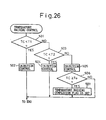
- the regeneration flag normally the temperature raising completion flag is reset, therefore the routine proceeds to step 500, where the control for raising the temperature is performed. This control for raising the temperature is shown in Fig. 26.
- step 501 it is determined if the temperature TC of the particulate filter 50 detected by the temperature sensor 39 is lower than the first temperature T1.
- step 502 injection is performed by the injection pattern determined based on (1) of Fig. 12.
- step 501 when it is determined at step 501 that TC ⁇ T1, the routine proceeds to step 503, where it is determined if the temperature TC of the particulate filter 50 detected by the temperature sensor 39 is lower than the second temperature T2.
- step 504 injection is performed by the injection pattern determined based on (2) of Fig. 12.
- step 503 when it is determined at step 503 that TC ⁇ T2, the routine proceeds to step 505, where injection is performed by the injection pattern determined based on (3) of Fig. 12.
- step 506 it is determined if the temperature TC of the particulate filter 50 detected by the temperature sensor 39 has become higher than the targeted fixed temperature T 0 .
- step 507 the routine proceeds to step 507, where the temperature raising completion flag is set.
- step 409 the temperature of the particulate filter 50 is held at least at the fixed temperature T 0 . That is, at this time, injection is performed by the injection pattern determined based on Fig. 24.
- step 410 it is determined if the differential pressure ⁇ P before and after the particulate filter 50 has become lower than a minimum value P min based on the output signal of the differential pressure sensor 52, that is, if all of the particulate matter deposited on the particulate filter 50 has been burned.
- ⁇ P ⁇ P min the routine proceeds to step 411, where the regeneration flag and the temperature raising completion flag are reset.
- a catalyst having an oxidation function such as an oxidation catalyst or a three-way catalyst inside the exhaust passage upstream or downstream of the NO x absorbent 22 in the first embodiment and inside the exhaust gas upstream or downstream of the particulate filter 50 in the second embodiment.
Landscapes
- Engineering & Computer Science (AREA)
- Chemical & Material Sciences (AREA)
- Combustion & Propulsion (AREA)
- Mechanical Engineering (AREA)
- General Engineering & Computer Science (AREA)
- Exhaust Gas After Treatment (AREA)
- Electrical Control Of Air Or Fuel Supplied To Internal-Combustion Engine (AREA)
- Processes For Solid Components From Exhaust (AREA)
- Fuel-Injection Apparatus (AREA)
Claims (28)
- Moteur à combustion interne (1) comportant une chambre de combustion (5) et un passage d'échappement (19), ledit moteur comprenant :caractérisé en ce queun moyen d'injection de carburant (7) destiné à injecter du carburant auxiliaire (QV ; Qe ; QP) dans la chambre de combustion (5), en plus du carburant principal (Q ; QR), selon la nécessité de produire des hydrocarbures non brûlés ;un dispositif après-traitement des gaz d'échappement (21) disposé dans le passage d'échappement (19), une température (TC) dudit dispositif après-traitement des gaz d'échappement (21) s'élevant lorsqu'une température des gaz d'échappement s'élève et s'élevant lorsque les hydrocarbures non brûlés sont délivrés vers le dispositif après-traitement des gaz d'échappement (21) ; etun moyen de commande d'injection (30) destiné à commander ledit moyen d'injection de carburant (7),
au moins deux motifs d'injection sont préétablis pour élever la température (TC) du dispositif après-traitement des gaz d'échappement (21) parmi un premier motif d'injection (II) retardant le calage d'injection du carburant principal (QR), comparé au cas dans lequel la température du dispositif après-traitement des gaz d'échappement (21) ne devrait pas s'élever, sans injecter le carburant auxiliaire (QV ; Qe ; QP), un deuxième motif d'injection (III) injectant le carburant auxiliaire (QV ; Qe) avant l'injection du carburant principal (QR) et retardant le calage d'injection du carburant principal (QR), et un troisième motif d'injection (IV-1 ; IV-2) injectant le carburant auxiliaire (QV, QP ; Qe, QP) avant l'injection du carburant principal (QR) et après l'injection du carburant principal (QR) et retardant le calage d'injection du carburant principal (QR), et
lorsque la température (TC) du dispositif après-traitement des gaz d'échappement (21) devrait être élevée, ledit moyen de commande d'injection (30) sélectionne l'un parmi les motifs d'injection à partir des motifs d'injection préétablis et injecte le carburant principal (QR) et le carburant auxiliaire (QV ; Qe ; QP) conformément au motif d'injection sélectionné, dont le motif d'injection devant être utilisé est déterminé conformément à la température (TC) du dispositif après-traitement des gaz d'échappement (21) ou conformément à la température (TC) du dispositif après-traitement des gaz d'échappement (21) et à l'état de fonctionnement (TQ, N) du moteur (1). - Moteur à combustion interne selon la revendication 1, dans lequel, dans le premier motif d'injection (II), le calage d'injection du carburant principal (QR) est retardé jusqu'à après le point mort haut de la course de compression.
- Moteur à combustion interne selon la revendication 1 ou 2, dans lequel, dans le deuxième motif d'injection (III), le carburant auxiliaire (QV) est injecté près du point mort haut de la course d'aspiration et la quantité de retard du calage d'injection du carburant principal (QR) est rendue plus importante que la quantité de retard du calage d'injection du carburant principal (QR) dans le premier motif d'injection (II).
- Moteur à combustion interne selon la revendication 3, dans lequel le carburant auxiliaire (QV) est injecté lorsqu'une soupape d'échappement (9) est ouverte.
- Moteur à combustion interne selon la revendication 3, dans lequel le calage d'injection du carburant auxiliaire (QV) est déterminé de sorte que le carburant auxiliaire injecté (QV) est dirigé vers une cavité (5a) formée dans une face supérieure d'un piston (4).
- Moteur à combustion interne selon la revendication 1 ou 2, dans lequel, dans le deuxième motif d'injection (III), le carburant auxiliaire (Qe) est injecté pendant la course de compression et la quantité de retard du calage d'injection du carburant principal (QR) est rendue plus importante que la quantité de retard du calage d'injection du carburant principal (QR) dans le premier motif d'injection (II).
- Moteur à combustion interne selon la revendication 6, dans lequel le calage d'injection du carburant auxiliaire (Qe) est déterminé de sorte que le carburant auxiliaire injecté (Qe) est dirigé vers une cavité (5a) formée dans une face supérieure d'un piston (4).
- Moteur à combustion interne selon l'une quelconque des revendications 1 à 5, dans lequel, dans le troisième motif d'injection (IV-1 ; IV-2), un premier carburant auxiliaire (QV) est injecté près du point mort haut de la course d'aspiration, un deuxième carburant auxiliaire (QP) est injecté pendant la course de combustion ou la course d'échappement, et la quantité de retard du calage d'injection du carburant principal (QR) est rendue plus importante que la quantité de retard du calage d'injection du carburant principal (QR) dans le premier motif d'injection (II).
- Moteur à combustion interne selon la revendication 8, dans lequel le premier carburant auxiliaire (QV) est injecté lorsqu'une soupape d'échappement (9) est ouverte.
- Moteur à combustion interne selon la revendication 8, dans lequel le calage d'injection du premier carburant auxiliaire (QV) est déterminé de sorte que le carburant auxiliaire injecté (QV) est dirigé vers une cavité (5a) formée dans une face supérieure d'un piston (4).
- Moteur à combustion interne selon la revendication 8, dans lequel le deuxième carburant auxiliaire (QP) est injecté pendant une course de combustion avant qu'une soupape d'échappement (9) s'ouvre.
- Moteur à combustion interne selon la revendication 8, dans lequel le deuxième carburant auxiliaire est injecté à des intervalles en plusieurs fois (QP).
- Moteur à combustion interne selon l'une quelconque des revendications 1, 2, 6 et 7, dans lequel, dans le troisième motif d'injection (IV-1 ; IV-2), le premier carburant auxiliaire (Qe) est injecté pendant la course de compression, le deuxième carburant auxiliaire (QP) est injecté pendant la course de combustion ou la course d'échappement, et la quantité de retard du calage d'injection du carburant principal (QR) est rendue plus importante que la quantité de retard du calage d'injection du carburant principal (QR) dans le premier motif d'injection (II).
- Moteur à combustion interne selon la revendication 13, dans lequel le calage d'injection du premier carburant auxiliaire est déterminé de sorte que le carburant auxiliaire injecté (Qe) est dirigé vers une cavité (5a) formée dans une face supérieure d'un piston (4).
- Moteur à combustion interne selon la revendication 13, dans lequel le deuxième carburant auxiliaire (QP) est injecté pendant la course de combustion avant qu'une soupape d'échappement (9) s'ouvre.
- Moteur à combustion interne selon la revendication 13, dans lequel le deuxième carburant auxiliaire (QP) est injecté à des intervalles en plusieurs fois.
- Moteur à combustion interne selon la revendication 1 ou 2, dans lequel, dans le quatrième motif d'injection (III-1 ; III-2 ; III-3) , le calage d'injection du carburant principal (QR) est retardé jusqu'à après le point mort haut de la course de compression et le carburant auxiliaire (QP) est injecté pendant la course de combustion ou la course d'échappement.
- Moteur à combustion interne selon la revendication 17, dans lequel le carburant auxiliaire (QP) est injecté pendant la course de combustion avant qu'une soupape d'échappement (9) s'ouvre.
- Moteur à combustion interne selon la revendication 17, dans lequel le carburant auxiliaire (QP) est injecté à des intervalles en plusieurs fois.
- Moteur à combustion interne selon l'une quelconque des revendications précédentes, dans lequel une première région de fonctionnement dans laquelle le carburant est injecté par le premier motif d'injection (II), une deuxième région de fonctionnement dans laquelle le carburant est injecté par le deuxième motif d'injection (III), et une troisième région de fonctionnement dans laquelle le carburant est injecté par le troisième motif d'injection (IV-1 ; IV-2) sont préétablies conformément à la température (TC) du dispositif après-traitement des gaz d'échappement (21) et à l'état de fonctionnement (TQ, N) du moteur.
- Moteur à combustion interne selon la revendication 20, dans lequel lorsque la température (TC) du dispositif après-traitement des gaz d'échappement (21) est inférieure à une température prédéterminée (T1), la majorité de la région de fonctionnement devient la troisième région de fonctionnement et lorsque la température du dispositif après-traitement des gaz d'échappement devient supérieure à la température prédéterminée (T1), la troisième région de fonctionnement est réduite à une plus petite région du côté faible charge.
- Moteur à combustion interne selon la revendication 21, dans lequel la deuxième région de fonctionnement est positionnée du côté charge élevée de la troisième région de fonctionnement et lorsque la température (TC) du dispositif après-traitement des gaz d'échappement (21) devient plus élevée, la deuxième région de fonctionnement se décale vers le côté faible charge.
- Moteur à combustion interne selon la revendication 22, dans lequel la première région de fonctionnement est positionnée du côté charge élevée de la deuxième région de fonctionnement et lorsque la température (TC) du dispositif après-traitement des gaz d'échappement (21) devient plus élevée, la première région de fonctionnement se décale vers le côté faible charge.
- Moteur à combustion interne selon l'une quelconque des revendications 1 à 23, dans lequel le dispositif après-traitement des gaz d'échappement (21) comprend un absorbant de NOx (22) qui absorbe les NOx lorsqu'un rapport air-carburant des gaz d'échappement est pauvre et libère les NOx lorsque le rapport air-carburant des gaz d'échappement devient le rapport air-carburant stoechiométrique ou riche, et la température (TC) de l'absorbant de NOx (22) est élevée lorsque les SOx doivent être libérés de l'absorbeur de NOx (22).
- Moteur à combustion interne selon la revendication 24, dans lequel le rapport air-carburant des gaz d'échappement est amené au rapport air-carburant stoechiométrique ou riche de façon à libérer les SOx de l'absorbant de NOx (22) après que la température (TC) de l'absorbant de NOx (22) ait dépassé une température cible prédéterminée (Tmax).
- Moteur à combustion interne selon la revendication 25, dans lequel un moyen de commande d'air d'admission (17) est prévu pour commander une quantité d'air d'admission, et lorsque les SOx doivent être libérés de l'absorbant de NOx (22), la quantité d'air d'admission est réduite par le moyen de commande d'air d'admission (17) et un quatrième motif d'injection (III-1 ; III-2 ; III-3) est utilisé par le moyen de commande d'injection (30), dans lequel le calage d'injection du carburant principal (QR) est retardé comparé au moment où la température (TC) de l'absorbant de NOx (22) ne devrait pas être élevée, et le carburant auxiliaire (QP) est injecté pendant la course de combustion ou la course d'échappement, d'où il résulte que le rapport air-carburant des gaz d'échappement est amené au rapport air-carburant stoechiométrique ou riche.
- Moteur à combustion interne selon l'une quelconque des revendications 1 à 23, dans lequel le dispositif après-traitement des gaz d'échappement (21) comprend un filtre particulaire (50) destiné à piéger les matières particulaires contenues dans les gaz d'échappement et la température du filtre particulaire (50) est élevée lorsque les matières particulières piégées par le filtre particulaire (50) doivent être brûlées.
- Moteur à combustion interne selon la revendication 27, dans lequel lorsque la température du filtre particulaire (50) dépasse une température prédéterminée (T0), les matières particulières piégées par le filtre particulaire (50) sont brûlées et, lorsque les matières particulières sont brûlées, le premier motif d'injection (III) est utilisé.
Applications Claiming Priority (2)
| Application Number | Priority Date | Filing Date | Title |
|---|---|---|---|
| JP35771899 | 1999-12-16 | ||
| JP35771899A JP3607980B2 (ja) | 1999-12-16 | 1999-12-16 | 内燃機関 |
Publications (3)
| Publication Number | Publication Date |
|---|---|
| EP1108876A2 EP1108876A2 (fr) | 2001-06-20 |
| EP1108876A3 EP1108876A3 (fr) | 2003-09-24 |
| EP1108876B1 true EP1108876B1 (fr) | 2005-12-14 |
Family
ID=18455568
Family Applications (1)
| Application Number | Title | Priority Date | Filing Date |
|---|---|---|---|
| EP00101967A Expired - Lifetime EP1108876B1 (fr) | 1999-12-16 | 2000-02-01 | Moteur à combustion interne |
Country Status (5)
| Country | Link |
|---|---|
| US (1) | US6378297B1 (fr) |
| EP (1) | EP1108876B1 (fr) |
| JP (1) | JP3607980B2 (fr) |
| DE (1) | DE60024762T2 (fr) |
| ES (1) | ES2254054T3 (fr) |
Cited By (1)
| Publication number | Priority date | Publication date | Assignee | Title |
|---|---|---|---|---|
| US12085216B2 (en) | 2022-02-17 | 2024-09-10 | Arctic Cat Inc. | Multi-use fuel filler tube |
Families Citing this family (76)
| Publication number | Priority date | Publication date | Assignee | Title |
|---|---|---|---|---|
| DE19963932A1 (de) * | 1999-12-31 | 2001-07-12 | Bosch Gmbh Robert | Verfahren zum Betreiben einer Brennkraftmaschine insbesondere eines Kraftfahrzeugs |
| ES2240403T3 (es) * | 2000-02-16 | 2005-10-16 | Toyota Jidosha Kabushiki Kaisha | Metodo de limpieza de gas de escape. |
| JP2003534480A (ja) * | 2000-03-09 | 2003-11-18 | ローベルト ボツシユ ゲゼルシヤフト ミツト ベシユレンクテル ハフツング | 内燃機関の燃料噴射制御方法および装置 |
| JP2001289093A (ja) * | 2000-03-31 | 2001-10-19 | Hitachi Ltd | 筒内噴射エンジンの排気制御装置 |
| JP4250856B2 (ja) * | 2000-05-24 | 2009-04-08 | 三菱自動車工業株式会社 | 筒内噴射型内燃機関 |
| JP3514218B2 (ja) * | 2000-07-24 | 2004-03-31 | トヨタ自動車株式会社 | 内燃機関の排気浄化装置 |
| DE10043375A1 (de) * | 2000-09-02 | 2002-03-14 | Bosch Gmbh Robert | Verfahren zur Aufheizung eines Katalysators bei Verbrennungsmotoren mit Benzindirekteinspritzung |
| DE10054005A1 (de) * | 2000-11-01 | 2002-05-08 | Daimler Chrysler Ag | Verfahren zum Betrieb einer Abgasreinigungsanlage mit Stickoxidspeicher |
| EP1553279B1 (fr) * | 2001-02-20 | 2007-08-15 | Isuzu Motors Limited | Procédé de commande d'injection de carburant pour moteur diesel et procédé de commande de regénération de gaz d'échappement après un dispositif de traitement |
| JP3838338B2 (ja) * | 2001-03-27 | 2006-10-25 | 三菱ふそうトラック・バス株式会社 | 内燃機関の排気浄化装置 |
| EP1245815B1 (fr) * | 2001-03-30 | 2006-06-07 | Mazda Motor Corporation | Moteur turbocompressé à allumage par étincelle et injection directe , méthode de commande, support de stockage lisible par ordinateur à cette fin. |
| JP2002364415A (ja) * | 2001-06-07 | 2002-12-18 | Mazda Motor Corp | エンジンの排気浄化装置 |
| JP2003041929A (ja) * | 2001-08-01 | 2003-02-13 | Toyota Motor Corp | 内燃機関の排気浄化装置 |
| ITTO20010786A1 (it) * | 2001-08-03 | 2003-02-03 | Fiat Ricerche | Metodo di autoinnesco della rigenerazione di un filtro particolato per un motore diesel ad iniezione diretta provvisto di un impianto di ini |
| DE10140120A1 (de) * | 2001-08-16 | 2003-03-06 | Bosch Gmbh Robert | Verfahren und Vorrichtung zum Betreiben eines Verbrennungsmotors |
| JP3810663B2 (ja) * | 2001-09-19 | 2006-08-16 | 三菱電機株式会社 | 内燃機関の排気ガス浄化方法、及び排気ガス浄化装置 |
| DE50110758D1 (de) * | 2001-09-25 | 2006-09-28 | Ford Global Tech Llc | Vorrichtung und Verfahren zur Regeneration einer Abgasbehandlungseinrichtung |
| JP3885545B2 (ja) * | 2001-10-12 | 2007-02-21 | 日産自動車株式会社 | 内燃機関の排気浄化装置 |
| JP2003120391A (ja) * | 2001-10-12 | 2003-04-23 | Isuzu Motors Ltd | 圧縮着火式内燃機関 |
| US6553757B1 (en) * | 2001-11-19 | 2003-04-29 | Ford Global Technologies, Llc | NOx purge air/fuel ratio selection |
| DE10158568A1 (de) * | 2001-11-29 | 2003-06-26 | Bosch Gmbh Robert | Verfahren und Anlage zur Regenerierung insbesondere Desulfatisierung eines Speicherkatalysators bei der Abgasreinigung |
| JP3929296B2 (ja) | 2001-11-30 | 2007-06-13 | トヨタ自動車株式会社 | 内燃機関 |
| JP3757856B2 (ja) * | 2001-12-07 | 2006-03-22 | トヨタ自動車株式会社 | 排気ガス浄化装置 |
| EP1475521B1 (fr) * | 2002-02-12 | 2019-03-27 | Isuzu Motors Limited | Systeme de decontamination de gaz d'echappement et procede de decontamination de gaz d'echappement |
| JP4075573B2 (ja) | 2002-06-13 | 2008-04-16 | 株式会社デンソー | 内燃機関の排ガス浄化装置 |
| JP2004068700A (ja) | 2002-08-06 | 2004-03-04 | Toyota Motor Corp | 排気ガス浄化方法 |
| KR101225517B1 (ko) * | 2002-09-13 | 2013-01-23 | 존슨 맛쎄이 퍼블릭 리미티드 컴파니 | 압축 점화 엔진 및 그것을 위한 배기 시스템 |
| FR2846372B1 (fr) * | 2002-10-23 | 2005-01-28 | Peugeot Citroen Automobiles Sa | Systeme d'aide a la regeneration d'un piege a nox a stockage/destockage, pour moteur diesel de vehicule |
| FR2846371B1 (fr) * | 2002-10-23 | 2005-01-28 | Peugeot Citroen Automobiles Sa | Systeme d'aide a la regeneration d'un piege a nox a stockage/destockage, pour moteur diesel de vehicule automobile |
| EP1416143A1 (fr) * | 2002-10-29 | 2004-05-06 | STMicroelectronics S.r.l. | Capteur virtuel pour des émissions d'un moteur à combustion interne et le système de commande d'injection |
| JP2004176657A (ja) * | 2002-11-28 | 2004-06-24 | Isuzu Motors Ltd | 燃料噴射制御装置 |
| US6981370B2 (en) | 2002-12-03 | 2006-01-03 | Caterpillar Inc | Method and apparatus for PM filter regeneration |
| JP4385593B2 (ja) * | 2002-12-10 | 2009-12-16 | トヨタ自動車株式会社 | 内燃機関の排気浄化装置 |
| JP4135495B2 (ja) * | 2002-12-20 | 2008-08-20 | いすゞ自動車株式会社 | 燃料噴射制御装置 |
| EP1581727B1 (fr) * | 2003-01-07 | 2010-11-10 | Peugeot Citroën Automobiles S.A. | Systeme d aide a la regeneration d un filtre a particul es d une ligne d echappement d un moteur diesel |
| DE602004002557T2 (de) * | 2003-01-07 | 2007-10-25 | Peugeot Citroën Automobiles S.A. | System zur regeneration eines partikelfilters in einer auspuffanlage |
| JP3912289B2 (ja) * | 2003-01-10 | 2007-05-09 | 日産自動車株式会社 | パティキュレートフィルタの再生装置及びエンジンの排気ガス浄化装置 |
| DE10310024B4 (de) * | 2003-02-28 | 2012-09-27 | Volkswagen Ag | Verfahren zur Aufheizung eines Katalysators |
| JP4367176B2 (ja) * | 2003-05-16 | 2009-11-18 | 株式会社デンソー | 内燃機関の排気浄化装置 |
| FR2855218B1 (fr) * | 2003-05-22 | 2007-03-09 | Renault Sa | Procede et systeme de gestion de la regeneration d'un filtre a particules et moteur a combustion interne equipe d'un tel filtres a particules |
| JP2005048751A (ja) * | 2003-07-31 | 2005-02-24 | Nissan Motor Co Ltd | エンジンの制御装置 |
| JP2005042661A (ja) * | 2003-07-25 | 2005-02-17 | Nissan Motor Co Ltd | 内燃機関の燃焼制御装置 |
| WO2005003537A1 (fr) * | 2003-07-08 | 2005-01-13 | Nissan Motor Co., Ltd. | Dispositif servant a controler la combustion d'un moteur |
| US7192463B2 (en) * | 2003-07-11 | 2007-03-20 | Cummins Filtration Ip, Inc. | Arrangement for mounting electrical components to an aftertreatment filter |
| JP2005048747A (ja) * | 2003-07-31 | 2005-02-24 | Nissan Motor Co Ltd | 内燃機関の燃焼制御装置 |
| JP4466008B2 (ja) * | 2003-07-31 | 2010-05-26 | 日産自動車株式会社 | エンジンの燃料噴射制御装置 |
| JP4556417B2 (ja) * | 2003-10-29 | 2010-10-06 | トヨタ自動車株式会社 | 内燃機関の排気浄化触媒昇温方法 |
| ITTO20030987A1 (it) | 2003-12-09 | 2005-06-10 | Fiat Ricerche | Metodo di controllo di un motore ad accensione spontanea provvisto di un impianto di iniezione a collettore comune durante la rigenerazione del filtro del particolato. |
| FR2873159B1 (fr) * | 2004-07-15 | 2008-04-25 | Peugeot Citroen Automobiles Sa | Systeme de desulfatation d'un piege a nox dispose dans une ligne d'echappement d'un moteur diesel de vehicule automobile |
| WO2006041545A2 (fr) * | 2004-10-04 | 2006-04-20 | Southwest Research Institute | Procede de desulfuration de pieges a nox pauvre et de regeneration simultanee d'un filtres a particules de moteur diesel |
| DE602004015612D1 (de) * | 2004-10-21 | 2008-09-18 | Ford Global Tech Llc | Steuerverfahren für das Luft-/Kraftstoffverhältnis |
| EP1653069B1 (fr) * | 2004-10-26 | 2018-03-21 | Volvo Car Corporation | Méthode et système de combustion pour améliorer des caractéristiques de combustion pour un moteur d'injection directe à diesel |
| JP4367335B2 (ja) * | 2004-12-27 | 2009-11-18 | 日産自動車株式会社 | エンジンの制御装置。 |
| US20060150616A1 (en) * | 2005-01-13 | 2006-07-13 | O'connor Justin M | Strategy for quenching incipient combustion of residual homogeneous charges during compession strokes in a diesel engine |
| US7481046B2 (en) * | 2005-02-28 | 2009-01-27 | Ford Global Technologies, Llc | Method of desulfating a NOx storage and conversion device |
| US7398644B2 (en) * | 2005-06-15 | 2008-07-15 | Ford Global Technologies, Llc | System and method for reducing NOx emissions in an apparatus having a diesel engine |
| JP3915822B2 (ja) * | 2005-09-07 | 2007-05-16 | いすゞ自動車株式会社 | 排気ガス浄化システムの脱硫制御方法及び排気ガス浄化システム |
| WO2007031157A1 (fr) * | 2005-09-17 | 2007-03-22 | Daimler Ag | Procede pour faire fonctionner un moteur a combustion a allumage commande |
| DE102006035139B4 (de) * | 2005-11-08 | 2020-03-12 | Daimler Ag | Verfahren zum Kaltlauf-Betrieb einer fremdgezündeten Brennkraftmaschine |
| US7325394B2 (en) * | 2006-04-27 | 2008-02-05 | Ford Global Technologies Llc | System and method for desulfating a NOx trap |
| DE602007004039D1 (de) | 2006-08-01 | 2010-02-11 | Honda Motor Co Ltd | Schwefelreinigungssteuerungsvorrichtung für einen Verbrennungsmotor |
| US8256210B2 (en) * | 2006-12-21 | 2012-09-04 | Cummins Inc. | Flexible fuel injection for multiple modes of diesel engine exhaust aftertreatment |
| JP4845762B2 (ja) * | 2007-02-13 | 2011-12-28 | 本田技研工業株式会社 | 内燃機関の排ガス浄化装置 |
| JP4355003B2 (ja) | 2007-03-08 | 2009-10-28 | 本田技研工業株式会社 | 内燃機関の制御装置 |
| DE102007020964A1 (de) * | 2007-05-04 | 2008-11-06 | Robert Bosch Gmbh | Verfahren zur Zylindergleichstellung einer Brennkraftmaschine |
| US7464690B1 (en) * | 2007-05-29 | 2008-12-16 | Wisconsin Alumni Research Foundation | Adaptive engine injection for emissions reduction |
| FR2921428B1 (fr) * | 2007-09-20 | 2010-02-26 | Renault Sas | Procede d'injection de carburant dans un cylindre de moteur a combustion interne |
| KR101091627B1 (ko) * | 2009-08-31 | 2011-12-08 | 기아자동차주식회사 | 배기 시스템 |
| US8387370B2 (en) * | 2009-09-29 | 2013-03-05 | Ford Global Technologies, Llc | System for regenerating a particulate filter and controlling EGR |
| DE102010038153B3 (de) | 2010-10-13 | 2012-03-08 | Ford Global Technologies, Llc. | Partikelsensor, Abgassystem und Verfahren zum Schutz von Komponenten eines turbogeladenen Motors mit Abgasrückführung |
| GB2513137B (en) * | 2013-04-16 | 2016-01-06 | Perkins Engines Co Ltd | Method and apparatus for exhaust gas aftertreatment device warming |
| US20160169164A1 (en) * | 2013-07-23 | 2016-06-16 | Mahindra & Mahindra Ltd. | Naturally aspirated common rail diesel engine meeting ultra low pm emission by passive exhaust after treatment |
| GB2524318B (en) * | 2014-03-21 | 2017-12-13 | Jaguar Land Rover Ltd | Method of injecting fuel into an internal combustion engine |
| SE538870C2 (en) | 2015-05-04 | 2017-01-17 | Scania Cv Ab | A method for operating a compression ignited engine and such an engine |
| US9995265B2 (en) * | 2015-05-25 | 2018-06-12 | Toyota Jidosha Kabushiki Kaisha | Control device for internal combustion engine |
| US11391230B2 (en) * | 2019-11-07 | 2022-07-19 | Saudi Arabian Oil Company | Compression ignition engines and methods for operating the same under cold start fast idle conditions |
Family Cites Families (23)
| Publication number | Priority date | Publication date | Assignee | Title |
|---|---|---|---|---|
| US4686827A (en) * | 1983-02-03 | 1987-08-18 | Ford Motor Company | Filtration system for diesel engine exhaust-II |
| EP0321451A3 (fr) * | 1984-03-31 | 1989-08-02 | Mitsubishi Jidosha Kogyo Kabushiki Kaisha | Système de régénération pour oxydeur à particules pour moteur diesel |
| JP2748686B2 (ja) * | 1990-11-16 | 1998-05-13 | トヨタ自動車株式会社 | 筒内直接噴射式火花点火機関 |
| IT1266889B1 (it) * | 1994-07-22 | 1997-01-21 | Fiat Ricerche | Metodo di autoinnesco della rigenerazione in un filtro particolato per un motore diesel con sistema d'iniezione a collettore comune. |
| JP3870430B2 (ja) | 1995-07-14 | 2007-01-17 | 三菱自動車工業株式会社 | 筒内噴射型内燃機関 |
| US5839275A (en) * | 1996-08-20 | 1998-11-24 | Toyota Jidosha Kabushiki Kaisha | Fuel injection control device for a direct injection type engine |
| DE59711876D1 (de) | 1996-09-05 | 2004-09-30 | Volkswagen Ag | Abgasreinigungsverfahren für eine brennkraftmaschine |
| DE19640161A1 (de) | 1996-09-28 | 1998-04-02 | Volkswagen Ag | NOx-Abgasreinigungsverfahren |
| JP3257423B2 (ja) * | 1996-12-12 | 2002-02-18 | 三菱自動車工業株式会社 | 排気昇温装置 |
| JP3337931B2 (ja) * | 1997-01-30 | 2002-10-28 | マツダ株式会社 | 筒内噴射式エンジン |
| JP3645704B2 (ja) * | 1997-03-04 | 2005-05-11 | トヨタ自動車株式会社 | 内燃機関の排気浄化装置 |
| JP3067685B2 (ja) * | 1997-03-31 | 2000-07-17 | 三菱自動車工業株式会社 | 火花点火式筒内噴射型内燃機関の排気浄化装置 |
| JP3116876B2 (ja) | 1997-05-21 | 2000-12-11 | トヨタ自動車株式会社 | 内燃機関 |
| DE19731131A1 (de) | 1997-07-19 | 1999-01-21 | Volkswagen Ag | Verfahren und Vorrichtung zur Regeneration einer Schwefelfalle |
| JP3424557B2 (ja) * | 1997-08-06 | 2003-07-07 | マツダ株式会社 | エンジンの排気浄化装置 |
| JP3340058B2 (ja) * | 1997-08-29 | 2002-10-28 | 本田技研工業株式会社 | 多気筒エンジンの空燃比制御装置 |
| DE19750226C1 (de) * | 1997-11-13 | 1998-10-29 | Daimler Benz Ag | Motorregelsystem für einen Dieselmotor |
| JP3092569B2 (ja) * | 1997-11-25 | 2000-09-25 | トヨタ自動車株式会社 | 圧縮着火式内燃機関 |
| JP3331935B2 (ja) * | 1997-12-04 | 2002-10-07 | トヨタ自動車株式会社 | 圧縮着火式内燃機関 |
| US5910096A (en) * | 1997-12-22 | 1999-06-08 | Ford Global Technologies, Inc. | Temperature control system for emission device coupled to direct injection engines |
| JP3225957B2 (ja) * | 1999-02-02 | 2001-11-05 | トヨタ自動車株式会社 | 内燃機関 |
| JP2000320386A (ja) * | 1999-03-10 | 2000-11-21 | Mazda Motor Corp | ディーゼルエンジンの燃料噴射装置 |
| FR2792036B1 (fr) * | 1999-04-06 | 2002-06-07 | Peugeot Citroen Automobiles Sa | Systeme d'aide a la regeneration d'un filtre a particules integre dans une ligne d'echappement d'un moteur diesel notamment de vehicule automobile |
-
1999
- 1999-12-16 JP JP35771899A patent/JP3607980B2/ja not_active Expired - Fee Related
-
2000
- 2000-02-01 DE DE60024762T patent/DE60024762T2/de not_active Expired - Lifetime
- 2000-02-01 EP EP00101967A patent/EP1108876B1/fr not_active Expired - Lifetime
- 2000-02-01 ES ES00101967T patent/ES2254054T3/es not_active Expired - Lifetime
- 2000-02-02 US US09/496,349 patent/US6378297B1/en not_active Expired - Lifetime
Cited By (1)
| Publication number | Priority date | Publication date | Assignee | Title |
|---|---|---|---|---|
| US12085216B2 (en) | 2022-02-17 | 2024-09-10 | Arctic Cat Inc. | Multi-use fuel filler tube |
Also Published As
| Publication number | Publication date |
|---|---|
| EP1108876A3 (fr) | 2003-09-24 |
| JP3607980B2 (ja) | 2005-01-05 |
| JP2001173498A (ja) | 2001-06-26 |
| EP1108876A2 (fr) | 2001-06-20 |
| DE60024762D1 (de) | 2006-01-19 |
| US6378297B1 (en) | 2002-04-30 |
| DE60024762T2 (de) | 2006-07-27 |
| ES2254054T3 (es) | 2006-06-16 |
Similar Documents
| Publication | Publication Date | Title |
|---|---|---|
| US6378297B1 (en) | Air-fuel control system for exhaust gas purification on ice | |
| EP1026385B1 (fr) | Moteur à combustion interne | |
| EP1148227B1 (fr) | Dispositif de purification de gaz d'échappement | |
| US7146800B2 (en) | Exhaust purification device and exhaust purification method of internal combustion engine | |
| CA2463696C (fr) | Dispositif et procede de purification des gaz d'echappement pour moteur thermique | |
| EP1300554B1 (fr) | Dispositif de purification de gaz d'échappement pour moteur à combustion interne | |
| EP0896141B1 (fr) | Commande de combustion et de recirculation des gaz d'échappement dans un moteur à combustion interne | |
| US5768887A (en) | Direct injection type compression ignition engine and method of use | |
| EP1304457B1 (fr) | Dispositif de regulation des emissions de gaz d'echappement d'un moteur a combustion interne | |
| US6470850B1 (en) | Internal combustion engine | |
| EP1302647B1 (fr) | Système de purification de gaz d'échappement pour moteur à combustion interne | |
| US6370869B1 (en) | Exhaust purification device of an engine | |
| EP1176289B1 (fr) | Système de commande de l'émission des gaz d'échappement pour moteurs à combustion interne | |
| US6715474B1 (en) | Internal combustion engine | |
| JP2002155724A (ja) | 内燃機関の排気浄化装置 | |
| EP1176298B1 (fr) | Système et méthode de commande de l'émission des gaz d'échappement pour moteurs à combustion interne | |
| EP1079084B1 (fr) | Moteur à combustion interne | |
| JP3551789B2 (ja) | 内燃機関 | |
| JP4052100B2 (ja) | 内燃機関の排気浄化装置 | |
| JP3424561B2 (ja) | 内燃機関 | |
| EP0997625A2 (fr) | Moteur à combustion interne |
Legal Events
| Date | Code | Title | Description |
|---|---|---|---|
| PUAI | Public reference made under article 153(3) epc to a published international application that has entered the european phase |
Free format text: ORIGINAL CODE: 0009012 |
|
| 17P | Request for examination filed |
Effective date: 20000201 |
|
| AK | Designated contracting states |
Kind code of ref document: A2 Designated state(s): AT BE CH CY DE DK ES FI FR GB GR IE IT LI LU MC NL PT SE |
|
| AX | Request for extension of the european patent |
Free format text: AL;LT;LV;MK;RO;SI |
|
| PUAL | Search report despatched |
Free format text: ORIGINAL CODE: 0009013 |
|
| AK | Designated contracting states |
Kind code of ref document: A3 Designated state(s): AT BE CH CY DE DK ES FI FR GB GR IE IT LI LU MC NL PT SE |
|
| AX | Request for extension of the european patent |
Extension state: AL LT LV MK RO SI |
|
| RIC1 | Information provided on ipc code assigned before grant |
Ipc: 7F 02D 41/02 B Ipc: 7F 02D 41/40 A Ipc: 7F 01N 3/20 B Ipc: 7F 02D 21/08 B |
|
| 17Q | First examination report despatched |
Effective date: 20031110 |
|
| AKX | Designation fees paid |
Designated state(s): DE ES FR GB IT |
|
| GRAP | Despatch of communication of intention to grant a patent |
Free format text: ORIGINAL CODE: EPIDOSNIGR1 |
|
| GRAS | Grant fee paid |
Free format text: ORIGINAL CODE: EPIDOSNIGR3 |
|
| GRAA | (expected) grant |
Free format text: ORIGINAL CODE: 0009210 |
|
| AK | Designated contracting states |
Kind code of ref document: B1 Designated state(s): DE ES FR GB IT |
|
| REG | Reference to a national code |
Ref country code: GB Ref legal event code: FG4D |
|
| REF | Corresponds to: |
Ref document number: 60024762 Country of ref document: DE Date of ref document: 20060119 Kind code of ref document: P |
|
| REG | Reference to a national code |
Ref country code: ES Ref legal event code: FG2A Ref document number: 2254054 Country of ref document: ES Kind code of ref document: T3 |
|
| ET | Fr: translation filed | ||
| PLBE | No opposition filed within time limit |
Free format text: ORIGINAL CODE: 0009261 |
|
| STAA | Information on the status of an ep patent application or granted ep patent |
Free format text: STATUS: NO OPPOSITION FILED WITHIN TIME LIMIT |
|
| 26N | No opposition filed |
Effective date: 20060915 |
|
| PGFP | Annual fee paid to national office [announced via postgrant information from national office to epo] |
Ref country code: IT Payment date: 20120215 Year of fee payment: 13 |
|
| REG | Reference to a national code |
Ref country code: GB Ref legal event code: 746 Effective date: 20121112 |
|
| REG | Reference to a national code |
Ref country code: DE Ref legal event code: R084 Ref document number: 60024762 Country of ref document: DE Effective date: 20121115 |
|
| PGFP | Annual fee paid to national office [announced via postgrant information from national office to epo] |
Ref country code: ES Payment date: 20130213 Year of fee payment: 14 Ref country code: GB Payment date: 20130130 Year of fee payment: 14 Ref country code: FR Payment date: 20130301 Year of fee payment: 14 Ref country code: DE Payment date: 20130131 Year of fee payment: 14 |
|
| REG | Reference to a national code |
Ref country code: DE Ref legal event code: R119 Ref document number: 60024762 Country of ref document: DE |
|
| GBPC | Gb: european patent ceased through non-payment of renewal fee |
Effective date: 20140201 |
|
| REG | Reference to a national code |
Ref country code: FR Ref legal event code: ST Effective date: 20141031 |
|
| REG | Reference to a national code |
Ref country code: DE Ref legal event code: R119 Ref document number: 60024762 Country of ref document: DE Effective date: 20140902 |
|
| PG25 | Lapsed in a contracting state [announced via postgrant information from national office to epo] |
Ref country code: FR Free format text: LAPSE BECAUSE OF NON-PAYMENT OF DUE FEES Effective date: 20140228 Ref country code: DE Free format text: LAPSE BECAUSE OF NON-PAYMENT OF DUE FEES Effective date: 20140902 Ref country code: GB Free format text: LAPSE BECAUSE OF NON-PAYMENT OF DUE FEES Effective date: 20140201 |
|
| REG | Reference to a national code |
Ref country code: ES Ref legal event code: FD2A Effective date: 20150529 |
|
| PG25 | Lapsed in a contracting state [announced via postgrant information from national office to epo] |
Ref country code: ES Free format text: LAPSE BECAUSE OF NON-PAYMENT OF DUE FEES Effective date: 20140202 |
|
| PG25 | Lapsed in a contracting state [announced via postgrant information from national office to epo] |
Ref country code: IT Free format text: LAPSE BECAUSE OF NON-PAYMENT OF DUE FEES Effective date: 20140201 |