EP1108894A2 - Pompe centrifuge pour des matières visqueuses - Google Patents
Pompe centrifuge pour des matières visqueuses Download PDFInfo
- Publication number
- EP1108894A2 EP1108894A2 EP00126934A EP00126934A EP1108894A2 EP 1108894 A2 EP1108894 A2 EP 1108894A2 EP 00126934 A EP00126934 A EP 00126934A EP 00126934 A EP00126934 A EP 00126934A EP 1108894 A2 EP1108894 A2 EP 1108894A2
- Authority
- EP
- European Patent Office
- Prior art keywords
- pump
- holder
- housing
- cutting
- pump according
- Prior art date
- Legal status (The legal status is an assumption and is not a legal conclusion. Google has not performed a legal analysis and makes no representation as to the accuracy of the status listed.)
- Granted
Links
- 239000011345 viscous material Substances 0.000 title description 2
- 230000002093 peripheral effect Effects 0.000 claims description 4
- 239000007787 solid Substances 0.000 description 8
- 238000011161 development Methods 0.000 description 4
- 230000018109 developmental process Effects 0.000 description 4
- 239000007788 liquid Substances 0.000 description 4
- 239000010902 straw Substances 0.000 description 3
- 241000792859 Enema Species 0.000 description 1
- 230000009286 beneficial effect Effects 0.000 description 1
- 230000000694 effects Effects 0.000 description 1
- 239000007920 enema Substances 0.000 description 1
- 229940095399 enema Drugs 0.000 description 1
- 239000000835 fiber Substances 0.000 description 1
- 239000002245 particle Substances 0.000 description 1
- 238000005086 pumping Methods 0.000 description 1
- 239000002002 slurry Substances 0.000 description 1
- 239000011343 solid material Substances 0.000 description 1
- 239000000126 substance Substances 0.000 description 1
Images

Classifications
-
- F—MECHANICAL ENGINEERING; LIGHTING; HEATING; WEAPONS; BLASTING
- F04—POSITIVE - DISPLACEMENT MACHINES FOR LIQUIDS; PUMPS FOR LIQUIDS OR ELASTIC FLUIDS
- F04D—NON-POSITIVE-DISPLACEMENT PUMPS
- F04D29/00—Details, component parts, or accessories
- F04D29/40—Casings; Connections of working fluid
- F04D29/42—Casings; Connections of working fluid for radial or helico-centrifugal pumps
- F04D29/426—Casings; Connections of working fluid for radial or helico-centrifugal pumps especially adapted for liquid pumps
-
- F—MECHANICAL ENGINEERING; LIGHTING; HEATING; WEAPONS; BLASTING
- F04—POSITIVE - DISPLACEMENT MACHINES FOR LIQUIDS; PUMPS FOR LIQUIDS OR ELASTIC FLUIDS
- F04D—NON-POSITIVE-DISPLACEMENT PUMPS
- F04D13/00—Pumping installations or systems
- F04D13/02—Units comprising pumps and their driving means
- F04D13/021—Units comprising pumps and their driving means containing a coupling
-
- F—MECHANICAL ENGINEERING; LIGHTING; HEATING; WEAPONS; BLASTING
- F04—POSITIVE - DISPLACEMENT MACHINES FOR LIQUIDS; PUMPS FOR LIQUIDS OR ELASTIC FLUIDS
- F04D—NON-POSITIVE-DISPLACEMENT PUMPS
- F04D13/00—Pumping installations or systems
- F04D13/02—Units comprising pumps and their driving means
- F04D13/06—Units comprising pumps and their driving means the pump being electrically driven
- F04D13/08—Units comprising pumps and their driving means the pump being electrically driven for submerged use
Definitions
- the invention relates to a pump, in particular a Centrifugal pump for thick matter, with a drive linkage, at the lower end of a housing with the pump a holder arranged at a distance from the drive linkage is, with the housing facing upwards Has enema.
- Such pumps are used in particular as slurry pumps used and in containers with pumpable, viscous substances lowered.
- the pump is on up lowered the bottom of the container.
- Inlet directed above is achieved that the on the Foreign objects located on the floor, such as Stones, not immediately sucked in.
- the invention is therefore based on the object To further develop the pump of the type mentioned at the beginning, that the suction of the pump is increased and a Clogging by foreign substances is effectively prevented.
- a pump especially a centrifugal pump for thick matter, with a Drive linkage, at its lower end Pump housing, or the actual pump, with a Holder is arranged at a distance from the drive linkage, the housing having an upward inlet has, the holder according to the invention straight line between the attachment points of the Holder on the drive linkage and the housing with a formed outward shape.
- This will reached a cross-sectional expansion, so that a particularly large inlet for the liquid to be pumped is ready.
- the holder is preferably essentially composed of two Striving formed. These connect the pump to the Drive linkage, so that between the struts only the drive shaft that extends inside the Drive linkage is arranged and in the pump Impeller drives. Basically, it is also possible to have three or more struts, but this will make the restricted space between the struts and the free cross section reduced. Basically, it is cheap to use as few struts as possible. Also the use of a single strut is conceivable.
- the holder preferably detects an arc exterior shape. Basically, they are also angular Forms conceivable, but it is preferred to use the holder to form an arc, as a result of which a higher Stability and easier editing possible becomes.
- the holder is particularly in the upper area domed on the outside and then extends essentially straight to the lower attachment point on the pump.
- the The holder is approximately crown-shaped in outline. Other shapes are also possible, such as one Form each strut of the holder as a semicircle.
- the holder is at least as wide trained as the pump. This will make a big one Cross section of the holder ensured. In particular is it is preferred to design the holder so that it fits into its largest external dimensions up to the pump housing extends beyond.
- the pump preferably has a spiral housing with a impeller arranged therein, so that an inlet of is given above and on the side the outlet from the pump takes place and from there, for example, via a hose is pumped up.
- the cutting propeller is preferably the same Drive shaft driven like one in the pump arranged impeller. This is the structure of the pump overall particularly easy. Furthermore, it is preferred design the cutting propeller to have two blades. Other propeller designs are also fundamentally possible, but it has been shown that a double wing Cutting propeller particularly good results in terms of the cutting effect.
- the inner surface adjacent to a peripheral edge of the cutting propeller is. This will ensure that Cutting propeller no large parts over to the inlet can reach. Rather, solids between the Cutting ring and the cutting propeller crushed.
- the upper one is also preferred Corner area of the cutting ring designed as a cutting edge, so that longer solid, such as straw, over this corner area can be drawn and cut off.
- the cutting propeller is preferably about halfway up arranged of the holder. This is particularly the case if the Holder is crown-shaped and above the Cutting propellers a comparatively large one Feed cross section remains.
- the Pump up a lower support bearing for the drive shaft.
- the drive shaft is additional in this support bearing stored so that protection against radial impacts consists.
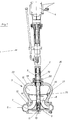
- Fig. 1 is a pump 1, namely a centrifugal pump for Depicted thick matter.
- the pump instructs Drive linkage 2 with a shaft 3 running therein.
- the wave is either direct from one Electric motor drive or an angular gear 4 from an engine, for example a tractor drive, operated.
- the drive linkage 2 is via a holder 5 connected to the housing 6, a spiral housing.
- the continuous shaft 3 drives in the housing 6 arranged impeller 7, which by the upward open inlet 8 pumps incoming liquid.
- the Housing 6 has a lower cover 9, the one has centrally arranged receptacle 10, into which a Support bearing 11 can be used, the shaft 3 in the lower Supported area and thus secures against radial impacts. Furthermore, there is a split ring 12 in the housing 6 intended.
- the parts of the housing 6 are essentially screwed together.
- the Fastened holder 5 which has two struts 15 and 16, which are arranged on opposite sides and in Outline about crown shape.
- the holder 15 is on its lower attachment point 17 in the outer area attached to the housing 6 and extends from there diagonally outwards and upwards.
- the Struts 16 and 17 In the upper area are the Struts 16 and 17 then guided in an arc and extend substantially horizontally to one upper attachment point 18 at which the holder with the Drive linkage 2 is connected.
- the drive linkage 2 has an outer tube 19 which is connected to a ring 20 is jammed.
- the drive linkage 2 is with the holder connected by screw connections.
- Fig. 2 the lower area of the pump is in shown perspective view.
- the spiral pump is also the outlet 28 recognizable.
- the cutting propeller 25 is arranged, which essentially consists of two semicircles that are twisted against each other are so that protruding cutting edges 29 are formed be and by the slope of the individual parts of the Cutting propeller 25 a pressure towards the inlet can be built.
- the supports 15 and 16 of the holder 5 have the of the attachment points 17 and 18 of the Support bulbous shape facing outwards.
Landscapes
- Engineering & Computer Science (AREA)
- Mechanical Engineering (AREA)
- General Engineering & Computer Science (AREA)
- Structures Of Non-Positive Displacement Pumps (AREA)
Applications Claiming Priority (2)
| Application Number | Priority Date | Filing Date | Title |
|---|---|---|---|
| DE19961196 | 1999-12-18 | ||
| DE19961196A DE19961196A1 (de) | 1999-12-18 | 1999-12-18 | Pumpe, insbesondere Kreiselpumpe für Dickstoffe |
Publications (3)
| Publication Number | Publication Date |
|---|---|
| EP1108894A2 true EP1108894A2 (fr) | 2001-06-20 |
| EP1108894A3 EP1108894A3 (fr) | 2002-07-17 |
| EP1108894B1 EP1108894B1 (fr) | 2004-05-06 |
Family
ID=7933235
Family Applications (1)
| Application Number | Title | Priority Date | Filing Date |
|---|---|---|---|
| EP00126934A Expired - Lifetime EP1108894B1 (fr) | 1999-12-18 | 2000-12-08 | Pompe centrifuge pour des matières visqueuses |
Country Status (4)
| Country | Link |
|---|---|
| EP (1) | EP1108894B1 (fr) |
| AT (1) | ATE266151T1 (fr) |
| DE (2) | DE19961196A1 (fr) |
| DK (1) | DK1108894T3 (fr) |
Cited By (1)
| Publication number | Priority date | Publication date | Assignee | Title |
|---|---|---|---|---|
| ITMI20130390A1 (it) * | 2013-03-15 | 2014-09-16 | Euroacque S R L | Pompa disincrostatrice |
Family Cites Families (9)
| Publication number | Priority date | Publication date | Assignee | Title |
|---|---|---|---|---|
| DD79227A (fr) * | ||||
| US2714354A (en) * | 1952-09-08 | 1955-08-02 | Orrin E Farrand | Pump |
| DE2040392A1 (de) * | 1970-08-13 | 1972-02-17 | Esterer Ag Maschf | Tauchschneidpumpe |
| DE2901638B1 (de) * | 1979-01-17 | 1979-08-30 | Gascoigne Suedstall Gmbh | Kreiselpumpe fuer mit Feststoffen versetzte Fluessigkeiten |
| DE3372396D1 (en) * | 1982-10-28 | 1987-08-13 | Goodwin R Int Ltd | Agitating particulate solids |
| DE3640813A1 (de) * | 1986-05-16 | 1987-11-26 | Emu Unterwasserpumpen Gmbh | Unterwasser-kreiselpumpe |
| US5256032A (en) * | 1992-05-26 | 1993-10-26 | Vaugan Co., Inc. | Centrifugal chopper pump |
| DE19609712A1 (de) * | 1996-03-13 | 1997-09-18 | Uts Umwelt Technik Sued Gmbh | Pumpe |
| DE19638080A1 (de) * | 1996-09-19 | 1998-03-26 | Uts Umwelt Technik Sued Gmbh | Pumpe |
-
1999
- 1999-12-18 DE DE19961196A patent/DE19961196A1/de not_active Withdrawn
-
2000
- 2000-12-08 DE DE50006317T patent/DE50006317D1/de not_active Expired - Fee Related
- 2000-12-08 AT AT00126934T patent/ATE266151T1/de not_active IP Right Cessation
- 2000-12-08 DK DK00126934T patent/DK1108894T3/da active
- 2000-12-08 EP EP00126934A patent/EP1108894B1/fr not_active Expired - Lifetime
Cited By (1)
| Publication number | Priority date | Publication date | Assignee | Title |
|---|---|---|---|---|
| ITMI20130390A1 (it) * | 2013-03-15 | 2014-09-16 | Euroacque S R L | Pompa disincrostatrice |
Also Published As
| Publication number | Publication date |
|---|---|
| EP1108894B1 (fr) | 2004-05-06 |
| DE19961196A1 (de) | 2001-06-28 |
| DK1108894T3 (da) | 2004-08-30 |
| EP1108894A3 (fr) | 2002-07-17 |
| ATE266151T1 (de) | 2004-05-15 |
| DE50006317D1 (de) | 2004-06-09 |
Similar Documents
| Publication | Publication Date | Title |
|---|---|---|
| DE1528763C3 (de) | Kreiselpumpe | |
| DE10327574B4 (de) | Laufrad für eine Kraftstoffpumpe | |
| DE102005014348B3 (de) | Pumpe mit Schneidlaufrad und Vorzerkleinerer | |
| DE69922198T2 (de) | Zentrifugalpumpe | |
| DE2117641A1 (de) | Vorrichtung zum Zerkleinern und Abpumpen von pumpbaren Abfällen | |
| DE2500860A1 (de) | Aufschlussvorrichtung | |
| EP3179112B1 (fr) | Couvercle de pompe avec trous formés comme filtres inertiels | |
| DE2021731B2 (de) | Vertikalachsiger Belüfterkreisel zum Belüften von Flüssigkeiten | |
| DE10327573A1 (de) | Einstufige Strömungspumpe | |
| EP1797327B1 (fr) | Pompe à pistons rotatifs comportant un carter et deux pistons rotatifs à deux pales | |
| DE112004001198T5 (de) | Laufradflügelaufbau für eine Zentrifugalpumpe | |
| DE69731091T2 (de) | Rotodynamische pumpe | |
| EP1213517B1 (fr) | Joint mécanique pour turbo machines | |
| DE1959262B2 (de) | Vertikalachsiger Belüftungskreisel zum Belüften von Abwassern oder der gleichen Flüssigkeiten | |
| EP2066200B1 (fr) | Passe-légumes | |
| DE19510811A1 (de) | Faser abweisende Wandflächengestaltung | |
| DE102008057849A1 (de) | Schneidvorrichtung einer Pumpe | |
| EP1108894B1 (fr) | Pompe centrifuge pour des matières visqueuses | |
| DE4321653C2 (de) | Stabmixer | |
| DE1653802B2 (de) | Pumpe zum foerdern von faserigen, dickfluessigen fluessigkeiten, wie mist, mit hohem gehalt an trockenmasse | |
| DE1528651B2 (de) | Schmutzwasserpumpe | |
| DE3238647A1 (de) | Mischer | |
| DE3640813A1 (de) | Unterwasser-kreiselpumpe | |
| DE6921357U (de) | Abwasserpumpe | |
| AT246480B (de) | Vorrichtung zum Rühren und Fördern von dicken Flüssigkeiten, wie Gülle, sowie Jauchegrube für diese Vorrichtung |
Legal Events
| Date | Code | Title | Description |
|---|---|---|---|
| PUAI | Public reference made under article 153(3) epc to a published international application that has entered the european phase |
Free format text: ORIGINAL CODE: 0009012 |
|
| AK | Designated contracting states |
Kind code of ref document: A2 Designated state(s): AT BE CH CY DE DK ES FI FR GB GR IE IT LI LU MC NL PT SE TR |
|
| AX | Request for extension of the european patent |
Free format text: AL;LT;LV;MK;RO;SI |
|
| PUAL | Search report despatched |
Free format text: ORIGINAL CODE: 0009013 |
|
| AK | Designated contracting states |
Kind code of ref document: A3 Designated state(s): AT BE CH CY DE DK ES FI FR GB GR IE IT LI LU MC NL PT SE TR |
|
| AX | Request for extension of the european patent |
Free format text: AL;LT;LV;MK;RO;SI |
|
| 17P | Request for examination filed |
Effective date: 20020716 |
|
| 17Q | First examination report despatched |
Effective date: 20021112 |
|
| AKX | Designation fees paid |
Designated state(s): AT BE CH CY DE DK ES FI FR GB GR IE IT LI LU MC NL PT SE TR |
|
| GRAP | Despatch of communication of intention to grant a patent |
Free format text: ORIGINAL CODE: EPIDOSNIGR1 |
|
| GRAS | Grant fee paid |
Free format text: ORIGINAL CODE: EPIDOSNIGR3 |
|
| GRAA | (expected) grant |
Free format text: ORIGINAL CODE: 0009210 |
|
| AK | Designated contracting states |
Kind code of ref document: B1 Designated state(s): AT BE CH CY DE DK ES FI FR GB GR IE IT LI LU MC NL PT SE TR |
|
| PG25 | Lapsed in a contracting state [announced via postgrant information from national office to epo] |
Ref country code: IT Free format text: LAPSE BECAUSE OF FAILURE TO SUBMIT A TRANSLATION OF THE DESCRIPTION OR TO PAY THE FEE WITHIN THE PRESCRIBED TIME-LIMIT;WARNING: LAPSES OF ITALIAN PATENTS WITH EFFECTIVE DATE BEFORE 2007 MAY HAVE OCCURRED AT ANY TIME BEFORE 2007. THE CORRECT EFFECTIVE DATE MAY BE DIFFERENT FROM THE ONE RECORDED. Effective date: 20040506 Ref country code: NL Free format text: LAPSE BECAUSE OF FAILURE TO SUBMIT A TRANSLATION OF THE DESCRIPTION OR TO PAY THE FEE WITHIN THE PRESCRIBED TIME-LIMIT Effective date: 20040506 Ref country code: FR Free format text: LAPSE BECAUSE OF FAILURE TO SUBMIT A TRANSLATION OF THE DESCRIPTION OR TO PAY THE FEE WITHIN THE PRESCRIBED TIME-LIMIT Effective date: 20040506 Ref country code: CY Free format text: LAPSE BECAUSE OF FAILURE TO SUBMIT A TRANSLATION OF THE DESCRIPTION OR TO PAY THE FEE WITHIN THE PRESCRIBED TIME-LIMIT Effective date: 20040506 Ref country code: FI Free format text: LAPSE BECAUSE OF FAILURE TO SUBMIT A TRANSLATION OF THE DESCRIPTION OR TO PAY THE FEE WITHIN THE PRESCRIBED TIME-LIMIT Effective date: 20040506 Ref country code: GB Free format text: LAPSE BECAUSE OF FAILURE TO SUBMIT A TRANSLATION OF THE DESCRIPTION OR TO PAY THE FEE WITHIN THE PRESCRIBED TIME-LIMIT Effective date: 20040506 Ref country code: ES Free format text: LAPSE BECAUSE OF FAILURE TO SUBMIT A TRANSLATION OF THE DESCRIPTION OR TO PAY THE FEE WITHIN THE PRESCRIBED TIME-LIMIT Effective date: 20040506 Ref country code: TR Free format text: LAPSE BECAUSE OF FAILURE TO SUBMIT A TRANSLATION OF THE DESCRIPTION OR TO PAY THE FEE WITHIN THE PRESCRIBED TIME-LIMIT Effective date: 20040506 Ref country code: IE Free format text: LAPSE BECAUSE OF FAILURE TO SUBMIT A TRANSLATION OF THE DESCRIPTION OR TO PAY THE FEE WITHIN THE PRESCRIBED TIME-LIMIT Effective date: 20040506 |
|
| REG | Reference to a national code |
Ref country code: GB Ref legal event code: FG4D Free format text: NOT ENGLISH |
|
| REG | Reference to a national code |
Ref country code: CH Ref legal event code: EP |
|
| REF | Corresponds to: |
Ref document number: 50006317 Country of ref document: DE Date of ref document: 20040609 Kind code of ref document: P |
|
| REG | Reference to a national code |
Ref country code: IE Ref legal event code: FG4D Free format text: GERMAN |
|
| PG25 | Lapsed in a contracting state [announced via postgrant information from national office to epo] |
Ref country code: GR Free format text: LAPSE BECAUSE OF FAILURE TO SUBMIT A TRANSLATION OF THE DESCRIPTION OR TO PAY THE FEE WITHIN THE PRESCRIBED TIME-LIMIT Effective date: 20040806 Ref country code: SE Free format text: LAPSE BECAUSE OF FAILURE TO SUBMIT A TRANSLATION OF THE DESCRIPTION OR TO PAY THE FEE WITHIN THE PRESCRIBED TIME-LIMIT Effective date: 20040806 |
|
| REG | Reference to a national code |
Ref country code: DK Ref legal event code: T3 |
|
| NLV1 | Nl: lapsed or annulled due to failure to fulfill the requirements of art. 29p and 29m of the patents act | ||
| GBV | Gb: ep patent (uk) treated as always having been void in accordance with gb section 77(7)/1977 [no translation filed] |
Effective date: 20040506 |
|
| PG25 | Lapsed in a contracting state [announced via postgrant information from national office to epo] |
Ref country code: LU Free format text: LAPSE BECAUSE OF NON-PAYMENT OF DUE FEES Effective date: 20041208 |
|
| REG | Reference to a national code |
Ref country code: IE Ref legal event code: FD4D |
|
| PG25 | Lapsed in a contracting state [announced via postgrant information from national office to epo] |
Ref country code: MC Free format text: LAPSE BECAUSE OF NON-PAYMENT OF DUE FEES Effective date: 20041231 Ref country code: CH Free format text: LAPSE BECAUSE OF NON-PAYMENT OF DUE FEES Effective date: 20041231 Ref country code: LI Free format text: LAPSE BECAUSE OF NON-PAYMENT OF DUE FEES Effective date: 20041231 Ref country code: BE Free format text: LAPSE BECAUSE OF NON-PAYMENT OF DUE FEES Effective date: 20041231 |
|
| PLBE | No opposition filed within time limit |
Free format text: ORIGINAL CODE: 0009261 |
|
| STAA | Information on the status of an ep patent application or granted ep patent |
Free format text: STATUS: NO OPPOSITION FILED WITHIN TIME LIMIT |
|
| EN | Fr: translation not filed | ||
| 26N | No opposition filed |
Effective date: 20050208 |
|
| BERE | Be: lapsed |
Owner name: *STALLKAMP ERICH Effective date: 20041231 |
|
| REG | Reference to a national code |
Ref country code: CH Ref legal event code: PL |
|
| BERE | Be: lapsed |
Owner name: *STALLKAMP ERICH Effective date: 20041231 |
|
| PG25 | Lapsed in a contracting state [announced via postgrant information from national office to epo] |
Ref country code: PT Free format text: LAPSE BECAUSE OF NON-PAYMENT OF DUE FEES Effective date: 20041006 |
|
| PGFP | Annual fee paid to national office [announced via postgrant information from national office to epo] |
Ref country code: DK Payment date: 20071220 Year of fee payment: 8 |
|
| PGFP | Annual fee paid to national office [announced via postgrant information from national office to epo] |
Ref country code: AT Payment date: 20071220 Year of fee payment: 8 |
|
| PGFP | Annual fee paid to national office [announced via postgrant information from national office to epo] |
Ref country code: DE Payment date: 20071018 Year of fee payment: 8 |
|
| REG | Reference to a national code |
Ref country code: DK Ref legal event code: EBP |
|
| PG25 | Lapsed in a contracting state [announced via postgrant information from national office to epo] |
Ref country code: AT Free format text: LAPSE BECAUSE OF NON-PAYMENT OF DUE FEES Effective date: 20081208 |
|
| PG25 | Lapsed in a contracting state [announced via postgrant information from national office to epo] |
Ref country code: DE Free format text: LAPSE BECAUSE OF NON-PAYMENT OF DUE FEES Effective date: 20090701 |
|
| PG25 | Lapsed in a contracting state [announced via postgrant information from national office to epo] |
Ref country code: DK Free format text: LAPSE BECAUSE OF NON-PAYMENT OF DUE FEES Effective date: 20090105 |