EP1108962A2 - Installation de chauffage avec chaudière, échangeurs de chaleur et plusieurs utilisateurs réglés par thermostat - Google Patents
Installation de chauffage avec chaudière, échangeurs de chaleur et plusieurs utilisateurs réglés par thermostat Download PDFInfo
- Publication number
- EP1108962A2 EP1108962A2 EP00123289A EP00123289A EP1108962A2 EP 1108962 A2 EP1108962 A2 EP 1108962A2 EP 00123289 A EP00123289 A EP 00123289A EP 00123289 A EP00123289 A EP 00123289A EP 1108962 A2 EP1108962 A2 EP 1108962A2
- Authority
- EP
- European Patent Office
- Prior art keywords
- heating
- heating system
- return
- flow
- control parameters
- Prior art date
- Legal status (The legal status is an assumption and is not a legal conclusion. Google has not performed a legal analysis and makes no representation as to the accuracy of the status listed.)
- Withdrawn
Links
Images
Classifications
-
- F—MECHANICAL ENGINEERING; LIGHTING; HEATING; WEAPONS; BLASTING
- F24—HEATING; RANGES; VENTILATING
- F24D—DOMESTIC- OR SPACE-HEATING SYSTEMS, e.g. CENTRAL HEATING SYSTEMS; DOMESTIC HOT-WATER SUPPLY SYSTEMS; ELEMENTS OR COMPONENTS THEREFOR
- F24D19/00—Details
- F24D19/10—Arrangement or mounting of control or safety devices
- F24D19/1006—Arrangement or mounting of control or safety devices for water heating systems
- F24D19/1009—Arrangement or mounting of control or safety devices for water heating systems for central heating
- F24D19/1012—Arrangement or mounting of control or safety devices for water heating systems for central heating by regulating the speed of a pump
-
- Y—GENERAL TAGGING OF NEW TECHNOLOGICAL DEVELOPMENTS; GENERAL TAGGING OF CROSS-SECTIONAL TECHNOLOGIES SPANNING OVER SEVERAL SECTIONS OF THE IPC; TECHNICAL SUBJECTS COVERED BY FORMER USPC CROSS-REFERENCE ART COLLECTIONS [XRACs] AND DIGESTS
- Y02—TECHNOLOGIES OR APPLICATIONS FOR MITIGATION OR ADAPTATION AGAINST CLIMATE CHANGE
- Y02B—CLIMATE CHANGE MITIGATION TECHNOLOGIES RELATED TO BUILDINGS, e.g. HOUSING, HOUSE APPLIANCES OR RELATED END-USER APPLICATIONS
- Y02B30/00—Energy efficient heating, ventilation or air conditioning [HVAC]
- Y02B30/70—Efficient control or regulation technologies, e.g. for control of refrigerant flow, motor or heating
Definitions
- the invention relates to a heating system with a controllable heat generator for a heating circuit fed by a heat exchanger with several thermostatically controlled Consumers, where the consumers with the assigned Thermostats are each connected in series and these series connections on Flow and return of the heat exchanger are connected in parallel.
- the heat generators are set up centrally and must supply the network heat via the heating circuit according to the current heating output requirements feed the consumer. This is done in the heating circuit flowing hot water.
- the heat exchanger is used by the heat generator supplied with heat, which it gives off to the water flowing in the heating circuit. To distribute the heat, a pump builds up pressure in the heating circuit.
- the heating circuit differs from application to application of the heat generator, since the line network to consumers is always different, too the number of consumers can vary and the thermal environment for the Heat generator and the heating circuit can change.
- This object is achieved according to the invention in that measuring devices the differential pressure between flow and return and the temperatures of the Flow and return measure that the measured values a microcomputer can be fed and that the microcomputer depending on the size and Modification of these measured values and taking into account specified operating procedures the control parameters for the heat generator changed.
- Identification companies are responsible for programming algorithms and equations provided, whereby the procedure is such that before commissioning of the heating system with different identification processes Conditions of the heating circuit and different heating power requirements in the microprocessor can be programmed to adapt the operating processes to it. The Operations are then based on the specific design of the heating circuit and the adapted to different heating output requirements.
- the degree of modulation can be adjusted using the control parameters and the clock behavior of the heat generator can be changed.
- a heat generator with a fan in the fuel supply circuit can the speed of the fan can be changed.
- For a heating circuit with one Pump can control parameters the operation of the pump - continuous operation, Impulse operation - change.
- control parameters contain manipulated variables for these controllable devices.
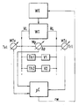
- a heat generator WE e.g. a gas boiler with burner supplies a heat exchanger WT with warmth.
- the water flowing through the heat exchanger WT is heated and passed through the heating circuit.
- the heating circuit can after execution several consumers controlled by thermostatic valves Th1 and Th2 V1 and V2, e.g. Radiators.
- the consumer V1 or V2 with the assigned thermostatic valves Th1 or Th2 connected in series. These series connections are connected in parallel with the Flow VL and return RL of the heat exchanger WT.
- the routes to consumers V1 and V2 of different lengths and can can also be matched to different heating power requirements.
- the measuring devices MTv and MTr measure the temperatures Tvl and Trl at the flow VL and at the return RL, the depend on the condition of the heating circuit and the heating output requirement.
- the measured values ⁇ p, Tvl and Trl are fed to a microcomputer ⁇ C, in identification mode with different operating conditions related to the specific design of the heating circuit and its requirements Programmed algorithms and equations for customized operations were. Taking into account the measurements according to size and The microcomputer ⁇ C can change the state of the heating circuit and close its requirements and use the stored ones Algorithms and equations, i.e. Operating procedures, control parameters rw to regulate the heat generator WE calculate that to an operating procedure the heating system, which in terms of efficiency, Emissions, noise and heating comfort is optimized.
- a pump in the heating circuit can reduce its total hydraulic resistance and the resulting total mass flow through the Heat exchanger determined and taken into account when regulating the heat generator WE weden. From the time course of the total hydraulic resistance and the temperature Trl at the return RL can be the current state of the coupled thermal-hydraulic overall system are identified, in each case the specific design of the heating circuit and its requirements and conditions are taken into account.
Landscapes
- Engineering & Computer Science (AREA)
- Physics & Mathematics (AREA)
- Thermal Sciences (AREA)
- Chemical & Material Sciences (AREA)
- Combustion & Propulsion (AREA)
- Mechanical Engineering (AREA)
- General Engineering & Computer Science (AREA)
- Steam Or Hot-Water Central Heating Systems (AREA)
- Heat-Pump Type And Storage Water Heaters (AREA)
Applications Claiming Priority (2)
| Application Number | Priority Date | Filing Date | Title |
|---|---|---|---|
| DE19960983A DE19960983A1 (de) | 1999-12-17 | 1999-12-17 | Heizungsanlage mit Wärmeerzeuger, Wärmetauscher und mehreren thermostatgesteuerten Verbrauchern |
| DE19960983 | 1999-12-17 |
Publications (2)
| Publication Number | Publication Date |
|---|---|
| EP1108962A2 true EP1108962A2 (fr) | 2001-06-20 |
| EP1108962A3 EP1108962A3 (fr) | 2002-12-18 |
Family
ID=7933091
Family Applications (1)
| Application Number | Title | Priority Date | Filing Date |
|---|---|---|---|
| EP00123289A Withdrawn EP1108962A3 (fr) | 1999-12-17 | 2000-10-27 | Installation de chauffage avec chaudière, échangeurs de chaleur et plusieurs utilisateurs réglés par thermostat |
Country Status (2)
| Country | Link |
|---|---|
| EP (1) | EP1108962A3 (fr) |
| DE (1) | DE19960983A1 (fr) |
Cited By (2)
| Publication number | Priority date | Publication date | Assignee | Title |
|---|---|---|---|---|
| EP2863133A1 (fr) * | 2013-10-15 | 2015-04-22 | Grundfos Holding A/S | Procédé pour régler la température de consigne d'un milieu de transfert de chaleur |
| EP3220065A1 (fr) * | 2016-03-14 | 2017-09-20 | Techem Energy Services GmbH | Méthode et appareil de contrôle pour augmenter le taux de performance d'un générateur de chaleur dans une installation de chauffage |
Family Cites Families (6)
| Publication number | Priority date | Publication date | Assignee | Title |
|---|---|---|---|---|
| EP0222040A3 (fr) * | 1985-11-11 | 1988-03-30 | IWK Regler und Kompensatoren GmbH | Installation de la technique du chauffage |
| AT398832B (de) * | 1990-11-19 | 1995-02-27 | Vaillant Gmbh | Zentralheizungsanlage |
| DE4421969A1 (de) * | 1994-06-23 | 1996-01-04 | Guido Dipl Ing Quick | Verfahren und Anordnung zur Ermittlung der von einem Strömungsmittel an einzelne, von einer gemeinsamen Wärmeträgereinspeisung betriebenen, Wärmeverbraucher übertragenen Wärmemenge |
| DE19506628A1 (de) * | 1995-02-25 | 1996-08-29 | Tekmar Elektronik Gmbh & Co | Verfahren und Anordnung zur Regelung eines Niedertemperatur-Heizsystems |
| DE19710905C1 (de) * | 1997-03-15 | 1998-07-02 | Robert Mack | Verfahren zum Betreiben einer Wärmeversorgungsanlage |
| DE19851524A1 (de) * | 1997-11-12 | 1999-05-20 | Ptg Planungsgemeinschaft Fuer | Raumheizungsanlage und Verfahren zum Betreiben derselben |
-
1999
- 1999-12-17 DE DE19960983A patent/DE19960983A1/de not_active Ceased
-
2000
- 2000-10-27 EP EP00123289A patent/EP1108962A3/fr not_active Withdrawn
Cited By (3)
| Publication number | Priority date | Publication date | Assignee | Title |
|---|---|---|---|---|
| EP2863133A1 (fr) * | 2013-10-15 | 2015-04-22 | Grundfos Holding A/S | Procédé pour régler la température de consigne d'un milieu de transfert de chaleur |
| US10746415B2 (en) | 2013-10-15 | 2020-08-18 | Grundfos Holding A/S | Method for adjusting the setpoint temperature of a heat transfer medium |
| EP3220065A1 (fr) * | 2016-03-14 | 2017-09-20 | Techem Energy Services GmbH | Méthode et appareil de contrôle pour augmenter le taux de performance d'un générateur de chaleur dans une installation de chauffage |
Also Published As
| Publication number | Publication date |
|---|---|
| DE19960983A1 (de) | 2001-07-05 |
| EP1108962A3 (fr) | 2002-12-18 |
Similar Documents
| Publication | Publication Date | Title |
|---|---|---|
| HUE027364T2 (en) | A method for controlling a single pipe heat supply system | |
| CH705804A1 (de) | Verfahren zur Regelung der Raumtemperatur in einem Raum oder einer Gruppe von mehreren Räumen sowie eine Vorrichtung zur Durchführung des Verfahrens. | |
| DE102010005275A1 (de) | Verfahren und Vorrichtung zum Einstellen einer Temperiereinrichtung | |
| AT515085B1 (de) | Verfahren zur adaptiven Regelung eines Heizsystems | |
| EP1645928A1 (fr) | Procédé de détermination de l'état d'alimentation d'une surface chauffante et régulateur d'état d'alimentation | |
| EP2372260B1 (fr) | Procédé de chauffage d'eau en continu et système de chauffage d'eau | |
| DE102014202738A1 (de) | Verfahren zum automatisierten hydraulischen Abgleich einer Heinzungsanlage | |
| EP1108962A2 (fr) | Installation de chauffage avec chaudière, échangeurs de chaleur et plusieurs utilisateurs réglés par thermostat | |
| CH684905A5 (de) | Verfahren zum Steuern der Auslauftemperatur und Vorrichtung zum Steuern der Auslauftemperatur. | |
| EP4071414A1 (fr) | Procédé, système et programme informatique de commande d'un générateur de chaleur | |
| WO2003023288A1 (fr) | Installation de chauffage central | |
| DE10329565B4 (de) | Verfahren und Einrichtung zur Einstellung der aus dem Fernwärmenetz bezogenen Wärmemenge auf den wirklichen Bedarfsfall einer Hausanschlußstation | |
| DE19710905C1 (de) | Verfahren zum Betreiben einer Wärmeversorgungsanlage | |
| DE102012101850A1 (de) | Verfahren zur bedarfsgeführten Regelung eines Wärmeerzeugers in einer Heizungsanlage | |
| WO1997034111A1 (fr) | Regulateur solaire a effet modulateur | |
| EP4015918B1 (fr) | Procédé et dispositif de commande d'un circuit primaire d'une installation de chauffage | |
| EP0229319B1 (fr) | Installation de chauffage à eau chaude avec calorimètre | |
| DE3838005C2 (fr) | ||
| EP0192225A2 (fr) | Procédé et dispositif de régulation de température de locaux | |
| DE102005041486B4 (de) | Anlage zur Erwärmung oder Vorwärmung von Wasser | |
| EP1508751A1 (fr) | Procédé et dispositif pour adapter la temperature de départ d'un générateur de chaleur à la charge respective du circuit de chauffage d'une installation de chauffage connectée en aval | |
| DE4110629C1 (en) | Heat or cooling generator regulator - has by=pass line between outward and return paths each with own temp. sensor | |
| DE4438881A1 (de) | Verfahren zum bedarfsangepaßten Betreiben einer Heizungsanlage | |
| EP4481280B1 (fr) | Installation de chauffage, procédé de fonctionnement d'une installation de chauffage et programme informatique | |
| DE2434223A1 (de) | Umlaufwasserheizer |
Legal Events
| Date | Code | Title | Description |
|---|---|---|---|
| PUAI | Public reference made under article 153(3) epc to a published international application that has entered the european phase |
Free format text: ORIGINAL CODE: 0009012 |
|
| AK | Designated contracting states |
Kind code of ref document: A2 Designated state(s): AT BE CH CY DE DK ES FI FR GB GR IE IT LI LU MC NL PT SE |
|
| AX | Request for extension of the european patent |
Free format text: AL;LT;LV;MK;RO;SI |
|
| PUAL | Search report despatched |
Free format text: ORIGINAL CODE: 0009013 |
|
| AK | Designated contracting states |
Kind code of ref document: A3 Designated state(s): AT BE CH CY DE DK ES FI FR GB GR IE IT LI LU MC NL PT SE |
|
| AX | Request for extension of the european patent |
Free format text: AL;LT;LV;MK;RO;SI |
|
| AKX | Designation fees paid | ||
| REG | Reference to a national code |
Ref country code: DE Ref legal event code: 8566 |
|
| STAA | Information on the status of an ep patent application or granted ep patent |
Free format text: STATUS: THE APPLICATION IS DEEMED TO BE WITHDRAWN |
|
| 18D | Application deemed to be withdrawn |
Effective date: 20030719 |