EP1109010B1 - Dispositif d'inspection - Google Patents
Dispositif d'inspection Download PDFInfo
- Publication number
- EP1109010B1 EP1109010B1 EP20000122931 EP00122931A EP1109010B1 EP 1109010 B1 EP1109010 B1 EP 1109010B1 EP 20000122931 EP20000122931 EP 20000122931 EP 00122931 A EP00122931 A EP 00122931A EP 1109010 B1 EP1109010 B1 EP 1109010B1
- Authority
- EP
- European Patent Office
- Prior art keywords
- leds
- light
- led array
- bottle
- brightness
- Prior art date
- Legal status (The legal status is an assumption and is not a legal conclusion. Google has not performed a legal analysis and makes no representation as to the accuracy of the status listed.)
- Expired - Lifetime
Links
- 238000007689 inspection Methods 0.000 title claims description 6
- 239000011248 coating agent Substances 0.000 claims description 2
- 238000000576 coating method Methods 0.000 claims description 2
- 239000002184 metal Substances 0.000 claims description 2
- 238000001228 spectrum Methods 0.000 claims 1
- 238000005286 illumination Methods 0.000 description 8
- 239000005338 frosted glass Substances 0.000 description 7
- 239000011521 glass Substances 0.000 description 4
- 238000012360 testing method Methods 0.000 description 3
- OAICVXFJPJFONN-UHFFFAOYSA-N Phosphorus Chemical compound [P] OAICVXFJPJFONN-UHFFFAOYSA-N 0.000 description 2
- 230000003287 optical effect Effects 0.000 description 2
- 241000257161 Calliphoridae Species 0.000 description 1
- 235000005940 Centaurea cyanus Nutrition 0.000 description 1
- 230000006978 adaptation Effects 0.000 description 1
- 238000011109 contamination Methods 0.000 description 1
- 230000003247 decreasing effect Effects 0.000 description 1
- 230000007547 defect Effects 0.000 description 1
- 238000001514 detection method Methods 0.000 description 1
- 238000011161 development Methods 0.000 description 1
- 238000011156 evaluation Methods 0.000 description 1
- 235000021384 green leafy vegetables Nutrition 0.000 description 1
- 238000000265 homogenisation Methods 0.000 description 1
- 239000000463 material Substances 0.000 description 1
- 238000000034 method Methods 0.000 description 1
- 238000002156 mixing Methods 0.000 description 1
- 239000011022 opal Substances 0.000 description 1
- 238000012856 packing Methods 0.000 description 1
- 239000003973 paint Substances 0.000 description 1
- 230000002093 peripheral effect Effects 0.000 description 1
- 230000001681 protective effect Effects 0.000 description 1
- 239000002689 soil Substances 0.000 description 1
- 238000011144 upstream manufacturing Methods 0.000 description 1
Images


Classifications
-
- G—PHYSICS
- G01—MEASURING; TESTING
- G01N—INVESTIGATING OR ANALYSING MATERIALS BY DETERMINING THEIR CHEMICAL OR PHYSICAL PROPERTIES
- G01N21/00—Investigating or analysing materials by the use of optical means, i.e. using sub-millimetre waves, infrared, visible or ultraviolet light
- G01N21/84—Systems specially adapted for particular applications
- G01N21/88—Investigating the presence of flaws or contamination
- G01N21/90—Investigating the presence of flaws or contamination in a container or its contents
- G01N21/9036—Investigating the presence of flaws or contamination in a container or its contents using arrays of emitters or receivers
Definitions
- the invention relates to an inspection device according to the preamble of claim 1.
- Inspection devices of this type have a lighting device, which is usually positioned laterally on a bottle conveyor during a transparency control of transparent bottles, while the light shining through the bottle is supplied on the opposite side of a camera.
- the images obtained from a bottle are analyzed by an associated evaluation device for the detection of defects, contamination or the like.
- an associated evaluation device for the detection of defects, contamination or the like.
- several circumferentially offset bottle images can be generated by special optical devices.
- a corresponding device is known for example from German Utility Model G 93 11 405.2.
- a partial illumination of the side wall of bottles is possible to define in a profile control dark areas behind the side edges of the body of bottles, so that a clear dark profile is supplied to the camera.
- a method and apparatus for testing transparent bottoms of bottles is known, with a lighting device for the bottom of bottles, which directs light with greater intensity on the peripheral region than on the central region of the soil and a distribution pattern of The light energy passing through the container bottom is generated along at least one of a direction corresponding in the plane of the container bottom. From this light energy distribution pattern, a pair of peak values along the direction and a corresponding pair of positions each having the peak values are obtained. Based on the positions thus obtained, the true center of the container bottom is calculated and a test zone around the true center is defined in exact agreement with the bottom of the container for analysis of the light energy only within the range of the test zone.
- the invention has for its object to provide a compact and yet optimal bottle illumination enabling lighting device.
- the lighting device that can be produced with little effort requires only a small structural depth.
- Another advantage is that, even with the use of a multi-image mirror cabinet, each image is equally bright, because in the larger beam path beam lengths between the bottle surface and the illumination device, the light comes from higher brightness LED areas, i. longer beam paths are compensated by higher brightness from the corresponding areas of the illumination device.
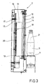
- the bottle sidewall control is carried out by an inspection station 1 arranged on a conveyor belt 4 which continuously conveys the bottles 5 to be tested and which consists essentially of a diffuse light emitting screen 2, a CCD camera 3 and between the conveyor 4 and the camera 3 arranged mirrors for generating a plurality of beam paths 6 ', 7', 8 'consists. Of these beam paths in each case only the central axis is indicated by dash-dotted lines.
- the vertically standing luminescent screen is aligned parallel to the conveyor belt and the longitudinal axis 21 of the bottles standing thereon.
- the two outer beam paths 6 and 7 are defined by two mirrors 6A and 6B or 7A and 7B, while the central beam path 8 is determined by three mirrors 8A, 8B and 8C. All three beam paths meet in the crossing area 9 in front of the screen 2 circumferentially offset directions on the outer surface of a transported in the direction of arrow bottle 5.
- the three beam paths due to the mirror arrangement made approximately the same length, while the beam sections from the bottle 5 to the flat frosted glass plate 10 of the phosphor screen 2 are unequal length, ie the corresponding section of the central beam path 8 'is shorter than that of the other two beam paths 6' and 7 '.
- German Utility Model G 93 11 405.2 for further details, reference is made to the aforementioned German Utility Model G 93 11 405.2.
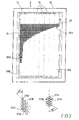
- the luminescent screen 2 has no brightness distribution which is uniform over its entire width, but a brightness progression decreasing toward the center from the two vertical edges 2A and 2B, which can be formed in accordance with an arbitrarily predefinable function. This is done with the aid of a different control of the LEDs 20 used as lighting means in the interior of the luminescent screen 2, the arrangement of which is better recognizable from FIG. There, the luminescent screen 2 is shown without its frosted glass pane with the side facing the camera 3 seen from the direction of the optical axis 12 of the camera.
- LEDs 20 boards 19 which form a flat, two-dimensional LED array 18, recognizable, which is formed in the present case of a total of eight vertically juxtaposed, strip-shaped board modules 19, wherein the vertical edge regions 18A and 18B of the array are formed by a board module 19A and 19B, respectively.
- the LEDs placed on the outer right module 19A and left module 19B shine brighter (about 30%) than the middle modules.
- the control of the LEDs is easily board by board, line by line or individually feasible.
- LEDs 20A (615 nanometers) and green LEDs 20B (520 nanometers) may be juxtaposed on the boards 19, the oranges being especially suited for amber and the greens for green glass.
- the LEDs of one or the other wavelength can be controlled or continuous mixing lights can be set, e.g. to examine blue bottles.
- the LEDs 20 are arranged on the boards 19 in vertical and horizontal rows aligned at right angles to each other.
- a better utilization of the available array area is achieved by a mutually offset arrangement of the LEDs, in which they are at an angle of 45 degrees intersecting lines (vertical and oblique lines).
- a geometric arrangement with a cutting angle of 60 degrees (vertical and oblique lines) allows the densest possible packing of the LEDs and thus the best brightness yield for a given area.
- the LEDs superior sheets 11, which form a closed frame and on their facing the LEDs surfaces have light-reflecting properties, preferably mirrored .
- Light striking the metal sheets is reflected to a frosted glass pane 10 (opal glass) arranged at a distance in front of the LEDs.
- the boards 19 bearing the LEDs are likewise provided with light-reflecting properties, be it by means of a paint application (white) or a reflective coating.
- a mirrored hole grid or - sheet (not shown) can be used, which is plugged via the LEDs 20 on the boards 19 and at the same time serves as an alignment grid of the LEDs.
- the boards 19 are attached to a rectangular frame 15 which is connected to the detachable rear wall 17 of the housing 16 of the phosphor screen 2.
Landscapes
- Physics & Mathematics (AREA)
- Health & Medical Sciences (AREA)
- Life Sciences & Earth Sciences (AREA)
- Chemical & Material Sciences (AREA)
- Analytical Chemistry (AREA)
- Biochemistry (AREA)
- General Health & Medical Sciences (AREA)
- General Physics & Mathematics (AREA)
- Immunology (AREA)
- Pathology (AREA)
- Investigating Materials By The Use Of Optical Means Adapted For Particular Applications (AREA)
Claims (10)
- Dispositif d'inspection (1) pour le contrôle des parois latérales de bouteilles (5) ou de récipients similaires, comprenant une installation d'éclairage (2) qui, lors d'un contrôle par transparence, est positionnée à côté d'un convoyeur de bouteilles (4), la lumière traversant la bouteille ou le récipient étant transmise à une caméra (3) située de l'autre côté,
caractérisé en ce que
le corps lumineux de l'installation d'éclairage est formé par une rangée de diodes électroluminescentes (18) dans un plan bidimensionnel dont les zones périphériques (18A, 18b) parallèles à l'axe longitudinal d'une bouteille émettent plus fortement que le centre, de sorte que pour des faisceaux lumineux ayant une plus longue trajectoire entre la surface de la bouteille et le système d'éclairage (2) la lumière provient des zones de diodes électroluminescentes de plus grande luminosité. - Dispositif selon la revendication 1,
caractérisé en ce que
la luminosité augmente de sensiblement 30 % du centre aux zones périphériques (18A, 18B). - Dispositif selon la revendication 1 ou 2,
caractérisé en ce que
sur ses bords extérieurs, la rangée de diodes électroluminescentes (18) présente un cadre réfléchissant (15). - Dispositif selon au moins l'une quelconque des revendications 1 à 3,
caractérisé en ce que
la rangée de diodes électroluminescentes (18) comprend au moins une platine (19) recevant les diodes électroluminescentes (20) à laquelle sont associés, sur sa face portant les diodes électroluminescentes, des moyens réfléchissant la lumière. - Dispositif selon la revendication 4,
caractérisé en ce qu'
un revêtement appliqué sur la surface de la platine ou une tôle perforée emboîtable au-dessus des diodes électroluminescentes sur la platine sont les moyens réfléchisssant la lumière. - Dispositif selon au moins l'une quelconque des revendications 1 à 5,
caractérisé en ce que
la rangée de diodes électroluminescentes (18) est formé à partir de plusieurs modules de platine (19) munis de diodes électroluminescentes (20), de préférence des modules en forme de bande. - Dispositif selon au moins l'une quelconque des revendications 1 à 6,
caractérisé en ce que
des diodes électroluminescentes (20) sont disposées de préférence côte à côte sur des lignes se coupant selon un angle de 45 ou 60 degrés. - Dispositif selon au moins l'une quelconque des revendications 1 à 7,
caractérisé en ce que
la rangée de diodes électroluminescentes (18) est muni de diodes électroluminescentes (20A, 20B) émettant une lumière dans différents spectres de couleur, de préférence des diodes électroluminescentes oranges ou vertes. - Dispositif selon au moins l'une quelconque des revendications 1 à 8,
caractérisé en ce que
la rangée de diodes électroluminescentes (18) est muni de diodes électroluminescentes (20) émettant sur une largeur homogène, en particulier dans une plage angulaire de 30 degrés à 45 degrés. - Dispositif selon la revendication 8,
caractérisé en ce que
les diodes électroluminescentes (20) peuvent être commandées de sorte que la luminosité des diodes électroluminescentes émettant une lumière d'une longueur d'onde déterminée soit variable par rapport à la luminosité des diodes électroluminescentes émettant une lumière d'une autre longueur d'onde.
Applications Claiming Priority (2)
| Application Number | Priority Date | Filing Date | Title |
|---|---|---|---|
| DE1999153738 DE19953738C1 (de) | 1999-11-09 | 1999-11-09 | Inspektionsvorrichtung zur Seitenwandkontrolle von Gefäßen |
| DE19953738 | 1999-11-09 |
Publications (3)
| Publication Number | Publication Date |
|---|---|
| EP1109010A1 EP1109010A1 (fr) | 2001-06-20 |
| EP1109010B1 true EP1109010B1 (fr) | 2006-06-28 |
| EP1109010B8 EP1109010B8 (fr) | 2006-09-06 |
Family
ID=7928336
Family Applications (1)
| Application Number | Title | Priority Date | Filing Date |
|---|---|---|---|
| EP20000122931 Expired - Lifetime EP1109010B8 (fr) | 1999-11-09 | 2000-10-21 | Dispositif d'inspection |
Country Status (2)
| Country | Link |
|---|---|
| EP (1) | EP1109010B8 (fr) |
| DE (2) | DE19953738C1 (fr) |
Cited By (1)
| Publication number | Priority date | Publication date | Assignee | Title |
|---|---|---|---|---|
| RU2742936C2 (ru) * | 2016-09-19 | 2021-02-11 | Тиама | Устройство для оптического контроля стеклянных сосудов на выходе формовочной машины |
Families Citing this family (12)
| Publication number | Priority date | Publication date | Assignee | Title |
|---|---|---|---|---|
| US7120284B2 (en) * | 2003-07-18 | 2006-10-10 | Emhart Glass S.A. | Container inspection machine |
| GB0611747D0 (en) * | 2006-06-14 | 2006-07-26 | Pilkington Plc | Glazing inspection |
| DE102008063077B4 (de) * | 2008-12-24 | 2017-12-07 | Krones Aktiengesellschaft | Inspektionsvorrichtung |
| DE102011106136A1 (de) * | 2011-06-10 | 2012-12-13 | Khs Gmbh | Leerflascheninspektion |
| DE102014104078B4 (de) * | 2014-03-25 | 2019-04-25 | Krones Ag | Inspektionsvorrichtung und Inspektionsverfahren zur Durchlichtinspektion von Behältern |
| DE102014220598B4 (de) * | 2014-10-10 | 2023-07-13 | Krones Aktiengesellschaft | Inspektionsvorrichtung und Verfahren zur Durchlichtinspektion von Behältern |
| IT201700039651A1 (it) * | 2017-04-11 | 2018-10-11 | Pe Labellers Spa | Dispositivo e metodo per orientare automaticamente contenitori in ingresso ad una macchina etichettatrice. |
| DE102017008406C5 (de) | 2017-09-07 | 2026-04-02 | Heuft Systemtechnik Gmbh | Inspektionsvorrichtung und ein Verfahren mit Farbbeleuchtung |
| DE102019208299A1 (de) * | 2019-06-06 | 2020-12-10 | Krones Ag | Verfahren und Vorrichtung zur optischen Inspektion von Behältern |
| DE102019208295A1 (de) * | 2019-06-06 | 2020-12-10 | Krones Ag | Verfahren und Vorrichtung zur optischen Inspektion von Behältern |
| FR3113131B1 (fr) * | 2020-07-29 | 2023-03-31 | Tiama | Dispositif et procédé d'inspection en transmission de récipients comportant au moins une source de lumière à diode électroluminescente |
| FR3132352B1 (fr) * | 2022-01-28 | 2024-12-13 | Tiama | Procédés et systèmes opto-informatiques d’inspection en lumière traversante d’un récipient en verre |
Family Cites Families (7)
| Publication number | Priority date | Publication date | Assignee | Title |
|---|---|---|---|---|
| DE3278861D1 (en) * | 1982-05-27 | 1988-09-08 | I2S | Automatic container testing process and device comparing transparency |
| JPH0711494B2 (ja) * | 1988-06-16 | 1995-02-08 | 松下電工株式会社 | 透光性容器の検査方法 |
| FR2642164B1 (fr) * | 1989-01-26 | 1991-04-12 | Saint Gobain Cinematique Contr | Controle d'objets a forte cadence |
| DE4022733C1 (en) * | 1989-12-19 | 1991-05-08 | Elpatronic Ag, Zug, Ch | Three=dimensional cavity inspection appts. - uses matrix or line camera to receive reflected light via gp. of four mirrors and deflecting mirror |
| US5314071A (en) * | 1992-12-10 | 1994-05-24 | Fmc Corporation | Glass sorter |
| DE9311405U1 (de) * | 1993-07-30 | 1994-09-22 | Kronseder Maschf Krones | Inspektionsmaschine |
| US6031221A (en) * | 1998-02-19 | 2000-02-29 | Emhart Glass S.A. | Container inspection machine |
-
1999
- 1999-11-09 DE DE1999153738 patent/DE19953738C1/de not_active Expired - Fee Related
-
2000
- 2000-10-21 DE DE50013086T patent/DE50013086D1/de not_active Expired - Lifetime
- 2000-10-21 EP EP20000122931 patent/EP1109010B8/fr not_active Expired - Lifetime
Cited By (1)
| Publication number | Priority date | Publication date | Assignee | Title |
|---|---|---|---|---|
| RU2742936C2 (ru) * | 2016-09-19 | 2021-02-11 | Тиама | Устройство для оптического контроля стеклянных сосудов на выходе формовочной машины |
Also Published As
| Publication number | Publication date |
|---|---|
| DE19953738C1 (de) | 2001-06-07 |
| DE50013086D1 (de) | 2006-08-10 |
| EP1109010A1 (fr) | 2001-06-20 |
| EP1109010B8 (fr) | 2006-09-06 |
Similar Documents
| Publication | Publication Date | Title |
|---|---|---|
| EP1109010B1 (fr) | Dispositif d'inspection | |
| DE102017008406C5 (de) | Inspektionsvorrichtung und ein Verfahren mit Farbbeleuchtung | |
| EP2537598A1 (fr) | Dispositif et procédé de tri optique de produits en vrac | |
| DE102015008409A1 (de) | Anlage zur optischen Überprüfung von Oberflächenbereichen von Gegenständen | |
| EP1288651B1 (fr) | Méthode et dispositif pour détecter des défauts optiques | |
| DE10017380B4 (de) | Behälterprüfmaschine | |
| DE10017381A1 (de) | Behälterprüfmaschine | |
| DE69519590T2 (de) | Sichtgerät und verfahren zum simultanen ermitteln der farbwechselcharakteristika eines optisch variablen gegenstandes | |
| DE212013000261U1 (de) | Beleuchtungssystem | |
| DE102008063077A1 (de) | Inspektionsvorrichtung | |
| DE69614452T2 (de) | Verfahren zum Messen des Verbiegungsgrades einer gebogenen Glasscheibe | |
| DE10234084B4 (de) | Vorrichtung zur Inspektion von bogenförmigen Material | |
| DE102005023534B4 (de) | Vorrichtung zum Inspizieren etikettierter Gefäße | |
| DE102016006780A1 (de) | Anlage zur optischen Überprüfung von Oberflächenbereichen von Gegenständen | |
| DE4322865A1 (de) | Gerät zur Messung der Farbe von Glas, insbesondere von Glasbruch | |
| EP3236198B1 (fr) | Éclairage en ligne commutable | |
| DE202014000264U1 (de) | Leuchtvorrichtung | |
| DE19820536C1 (de) | Einrichtung zur Überprüfung einer Oberfläche eines Körpers, insbesondere einer Lackoberfläche eines Kraftfahrzeuges | |
| DE102022102253A1 (de) | Inspektionsvorrichtung mit Mehr-Kanal-Detektionseinheit | |
| DE102014215481A1 (de) | Leuchte für eine Arbeitsumgebung, insbesondere zum Prüfen der Oberfläche von Werkstücken | |
| DE102016100437B4 (de) | Vorrichtung zur Druckbildkontrolle | |
| DE10252523A1 (de) | Beleuchtungsvorrichtung zur optischen Prüfung | |
| DE19832615B4 (de) | Verfahren und Vorrichtung zur Erkennung der jeweiligen Form mehrerer in einem Kasten befindlicher flaschenförmiger Behälter | |
| EP0947827A1 (fr) | Dispositif pour l'inspection visuelle de surfaces de corps situées dans des plans différents | |
| DE102008013525B4 (de) | Vorrichtung und Verfahren zum kontaktlosen Erkennen von Charakteristika von kontinuierlich geförderten, transluzenten Produkten |
Legal Events
| Date | Code | Title | Description |
|---|---|---|---|
| PUAI | Public reference made under article 153(3) epc to a published international application that has entered the european phase |
Free format text: ORIGINAL CODE: 0009012 |
|
| 17P | Request for examination filed |
Effective date: 20010227 |
|
| AK | Designated contracting states |
Kind code of ref document: A1 Designated state(s): CH FR GB IT LI Kind code of ref document: A1 Designated state(s): CH DE FR GB IT LI |
|
| AX | Request for extension of the european patent |
Free format text: AL;LT;LV;MK;RO;SI |
|
| 17Q | First examination report despatched |
Effective date: 20010514 |
|
| AKX | Designation fees paid |
Free format text: CH DE FR GB IT LI |
|
| RBV | Designated contracting states (corrected) |
Designated state(s): CH FR GB IT LI |
|
| REG | Reference to a national code |
Ref country code: DE Ref legal event code: 8566 |
|
| APAF | Appeal reference modified |
Free format text: ORIGINAL CODE: EPIDOSCREFNE |
|
| APBT | Appeal procedure closed |
Free format text: ORIGINAL CODE: EPIDOSNNOA9E |
|
| GRAP | Despatch of communication of intention to grant a patent |
Free format text: ORIGINAL CODE: EPIDOSNIGR1 |
|
| GRAS | Grant fee paid |
Free format text: ORIGINAL CODE: EPIDOSNIGR3 |
|
| GRAA | (expected) grant |
Free format text: ORIGINAL CODE: 0009210 |
|
| RBV | Designated contracting states (corrected) |
Designated state(s): CH DE FR GB IT LI |
|
| AK | Designated contracting states |
Kind code of ref document: B1 Designated state(s): CH DE FR GB IT LI |
|
| PG25 | Lapsed in a contracting state [announced via postgrant information from national office to epo] |
Ref country code: IT Free format text: LAPSE BECAUSE OF FAILURE TO SUBMIT A TRANSLATION OF THE DESCRIPTION OR TO PAY THE FEE WITHIN THE PRESCRIBED TIME-LIMIT;WARNING: LAPSES OF ITALIAN PATENTS WITH EFFECTIVE DATE BEFORE 2007 MAY HAVE OCCURRED AT ANY TIME BEFORE 2007. THE CORRECT EFFECTIVE DATE MAY BE DIFFERENT FROM THE ONE RECORDED. Effective date: 20060628 |
|
| REG | Reference to a national code |
Ref country code: GB Ref legal event code: FG4D Free format text: NOT ENGLISH |
|
| REG | Reference to a national code |
Ref country code: CH Ref legal event code: EP Ref country code: CH Ref legal event code: NV Representative=s name: PATENTANWALTSBUERO JEAN HUNZIKER |
|
| REF | Corresponds to: |
Ref document number: 50013086 Country of ref document: DE Date of ref document: 20060810 Kind code of ref document: P |
|
| RBV | Designated contracting states (corrected) |
Designated state(s): CH FR GB IT LI |
|
| GBT | Gb: translation of ep patent filed (gb section 77(6)(a)/1977) |
Effective date: 20060821 |
|
| ET | Fr: translation filed | ||
| PLBE | No opposition filed within time limit |
Free format text: ORIGINAL CODE: 0009261 |
|
| STAA | Information on the status of an ep patent application or granted ep patent |
Free format text: STATUS: NO OPPOSITION FILED WITHIN TIME LIMIT |
|
| 26N | No opposition filed |
Effective date: 20070329 |
|
| PGFP | Annual fee paid to national office [announced via postgrant information from national office to epo] |
Ref country code: CH Payment date: 20121012 Year of fee payment: 13 Ref country code: FR Payment date: 20121018 Year of fee payment: 13 |
|
| PGFP | Annual fee paid to national office [announced via postgrant information from national office to epo] |
Ref country code: GB Payment date: 20121017 Year of fee payment: 13 |
|
| REG | Reference to a national code |
Ref country code: CH Ref legal event code: PL |
|
| GBPC | Gb: european patent ceased through non-payment of renewal fee |
Effective date: 20131021 |
|
| PG25 | Lapsed in a contracting state [announced via postgrant information from national office to epo] |
Ref country code: GB Free format text: LAPSE BECAUSE OF NON-PAYMENT OF DUE FEES Effective date: 20131021 Ref country code: LI Free format text: LAPSE BECAUSE OF NON-PAYMENT OF DUE FEES Effective date: 20131031 Ref country code: CH Free format text: LAPSE BECAUSE OF NON-PAYMENT OF DUE FEES Effective date: 20131031 |
|
| REG | Reference to a national code |
Ref country code: FR Ref legal event code: ST Effective date: 20140630 |
|
| PG25 | Lapsed in a contracting state [announced via postgrant information from national office to epo] |
Ref country code: FR Free format text: LAPSE BECAUSE OF NON-PAYMENT OF DUE FEES Effective date: 20131031 |
|
| PGFP | Annual fee paid to national office [announced via postgrant information from national office to epo] |
Ref country code: IT Payment date: 20141008 Year of fee payment: 15 |
|
| PG25 | Lapsed in a contracting state [announced via postgrant information from national office to epo] |
Ref country code: IT Free format text: LAPSE BECAUSE OF NON-PAYMENT OF DUE FEES Effective date: 20151021 |