EP1109034A1 - Verfahren und Einrichtung zur Untersuchung und Identifizierung der Art eines Untergrundes - Google Patents
Verfahren und Einrichtung zur Untersuchung und Identifizierung der Art eines Untergrundes Download PDFInfo
- Publication number
- EP1109034A1 EP1109034A1 EP00811161A EP00811161A EP1109034A1 EP 1109034 A1 EP1109034 A1 EP 1109034A1 EP 00811161 A EP00811161 A EP 00811161A EP 00811161 A EP00811161 A EP 00811161A EP 1109034 A1 EP1109034 A1 EP 1109034A1
- Authority
- EP
- European Patent Office
- Prior art keywords
- shock wave
- characteristic
- tool
- drill
- values
- Prior art date
- Legal status (The legal status is an assumption and is not a legal conclusion. Google has not performed a legal analysis and makes no representation as to the accuracy of the status listed.)
- Granted
Links
- 238000000034 method Methods 0.000 title claims abstract description 48
- 238000011835 investigation Methods 0.000 title description 2
- 230000035939 shock Effects 0.000 claims abstract description 27
- 239000000463 material Substances 0.000 claims abstract description 14
- 238000005065 mining Methods 0.000 claims description 17
- 238000001228 spectrum Methods 0.000 claims description 14
- 238000012935 Averaging Methods 0.000 claims description 9
- 238000013016 damping Methods 0.000 claims description 8
- 238000005259 measurement Methods 0.000 claims description 8
- 238000000605 extraction Methods 0.000 claims description 6
- 230000000694 effects Effects 0.000 claims description 5
- 230000003595 spectral effect Effects 0.000 claims description 4
- 238000011156 evaluation Methods 0.000 claims description 3
- 239000000758 substrate Substances 0.000 claims description 2
- 238000009412 basement excavation Methods 0.000 claims 1
- 230000000149 penetrating effect Effects 0.000 abstract 1
- 238000001514 detection method Methods 0.000 description 10
- 230000006870 function Effects 0.000 description 10
- 238000004458 analytical method Methods 0.000 description 9
- 238000005553 drilling Methods 0.000 description 7
- 238000012937 correction Methods 0.000 description 5
- 238000004364 calculation method Methods 0.000 description 4
- 238000009659 non-destructive testing Methods 0.000 description 4
- 238000004804 winding Methods 0.000 description 4
- 241000272478 Aquila Species 0.000 description 3
- 239000011449 brick Substances 0.000 description 3
- 230000005284 excitation Effects 0.000 description 3
- 238000012545 processing Methods 0.000 description 3
- 239000011435 rock Substances 0.000 description 3
- 238000012360 testing method Methods 0.000 description 3
- 238000004154 testing of material Methods 0.000 description 3
- 238000013528 artificial neural network Methods 0.000 description 2
- 238000010276 construction Methods 0.000 description 2
- 230000001419 dependent effect Effects 0.000 description 2
- 238000005457 optimization Methods 0.000 description 2
- 238000003908 quality control method Methods 0.000 description 2
- 238000005070 sampling Methods 0.000 description 2
- 230000001360 synchronised effect Effects 0.000 description 2
- 101100120142 Saccharomyces cerevisiae (strain ATCC 204508 / S288c) FIR1 gene Proteins 0.000 description 1
- 238000013459 approach Methods 0.000 description 1
- 238000013473 artificial intelligence Methods 0.000 description 1
- 230000004323 axial length Effects 0.000 description 1
- 239000000919 ceramic Substances 0.000 description 1
- 238000013461 design Methods 0.000 description 1
- 230000001066 destructive effect Effects 0.000 description 1
- 238000011161 development Methods 0.000 description 1
- 230000018109 developmental process Effects 0.000 description 1
- 238000010586 diagram Methods 0.000 description 1
- 238000001914 filtration Methods 0.000 description 1
- 238000012886 linear function Methods 0.000 description 1
- 239000000696 magnetic material Substances 0.000 description 1
- 238000004519 manufacturing process Methods 0.000 description 1
- 244000052769 pathogen Species 0.000 description 1
- 230000001717 pathogenic effect Effects 0.000 description 1
- 238000011144 upstream manufacturing Methods 0.000 description 1
- 238000012795 verification Methods 0.000 description 1
Images


Classifications
-
- B—PERFORMING OPERATIONS; TRANSPORTING
- B25—HAND TOOLS; PORTABLE POWER-DRIVEN TOOLS; MANIPULATORS
- B25D—PERCUSSIVE TOOLS
- B25D16/00—Portable percussive machines with superimposed rotation, the rotational movement of the output shaft of a motor being modified to generate axial impacts on the tool bit
-
- E—FIXED CONSTRUCTIONS
- E21—EARTH OR ROCK DRILLING; MINING
- E21B—EARTH OR ROCK DRILLING; OBTAINING OIL, GAS, WATER, SOLUBLE OR MELTABLE MATERIALS OR A SLURRY OF MINERALS FROM WELLS
- E21B44/00—Automatic control systems specially adapted for drilling operations, i.e. self-operating systems which function to carry out or modify a drilling operation without intervention of a human operator, e.g. computer-controlled drilling systems; Systems specially adapted for monitoring a plurality of drilling variables or conditions
-
- G—PHYSICS
- G01—MEASURING; TESTING
- G01V—GEOPHYSICS; GRAVITATIONAL MEASUREMENTS; DETECTING MASSES OR OBJECTS; TAGS
- G01V1/00—Seismology; Seismic or acoustic prospecting or detecting
- G01V1/40—Seismology; Seismic or acoustic prospecting or detecting specially adapted for well-logging
- G01V1/44—Seismology; Seismic or acoustic prospecting or detecting specially adapted for well-logging using generators and receivers in the same well
-
- E—FIXED CONSTRUCTIONS
- E21—EARTH OR ROCK DRILLING; MINING
- E21B—EARTH OR ROCK DRILLING; OBTAINING OIL, GAS, WATER, SOLUBLE OR MELTABLE MATERIALS OR A SLURRY OF MINERALS FROM WELLS
- E21B2200/00—Special features related to earth drilling for obtaining oil, gas or water
- E21B2200/22—Fuzzy logic, artificial intelligence, neural networks or the like
-
- Y—GENERAL TAGGING OF NEW TECHNOLOGICAL DEVELOPMENTS; GENERAL TAGGING OF CROSS-SECTIONAL TECHNOLOGIES SPANNING OVER SEVERAL SECTIONS OF THE IPC; TECHNICAL SUBJECTS COVERED BY FORMER USPC CROSS-REFERENCE ART COLLECTIONS [XRACs] AND DIGESTS
- Y10—TECHNICAL SUBJECTS COVERED BY FORMER USPC
- Y10T—TECHNICAL SUBJECTS COVERED BY FORMER US CLASSIFICATION
- Y10T408/00—Cutting by use of rotating axially moving tool
- Y10T408/16—Cutting by use of rotating axially moving tool with control means energized in response to activator stimulated by condition sensor
Definitions
- the invention relates to a method and a method using this method Facility for examining and identifying the type of one for mining provided underground and to provide at least one operating parameter for optimized presetting of a mining device.
- a process is described in patent publication DE 3 518 370 (see ref. [4]) described in which the shock wave is controlled during rock drilling.
- the measured shock wave or quantities derived therefrom such as Spectrum, decay behavior, amplitude values, compared with a target value.
- By changing one or more manipulated variables, such as stroke frequency, Impact force, rotational speed, torque and / or feed force the deviation of the measured variable from the setpoint is kept to a minimum.
- the invention is therefore based on the object of a method and a device indicate by which during or immediately before a mining operation, So for example a drilling process, a detection of the type of for Removal of the proposed subsoil takes place using the data obtained in this way at least some operating parameters essential for an optimal mining operation to be able to set the mining device automatically.
- This task is carried out in a method generally defined at the outset Investigation and identification of a subsurface intended for mining solved in that before or at the beginning and during a mining operation one generated or induced in a tool of the mining device Shock wave detected and at least one from the shock wave signal thus measured characteristic characteristic for the subsurface extracted and for classification of the subsurface is evaluated using an algorithm.
- the background is identified by an algorithmic analysis of Longitudinal waves.
- These can e.g. B. Shock waves measured directly in the tool or the sound waves emitted by the tool or surface, in particular Be sound waves.
- the subsurface additionally at least one external force acting on the mining device, for example the contact pressure to be included in the subsequent signal processing.
- the shock wave can be measured by sensors, for example based on the magnetoelastic (ME) effect, based on strain gauges or based on surface waves.
- the background determination is carried out with this tried and tested variant the invention by calculating four features and a subsequent one weighted decision.
- the shock wave is measured in Drill 2 of a rotary hammer 3 uses a sensor 1, which according to magnetoelastic effect works (compare [Ref. 7]).
- the ME sensor 1 surrounds the shaft of the drill 2 is annular and consists essentially of a excitation winding surrounded by a soft magnetic material and a also arranged within the soft magnetic casing, the Drill shaft within the sensor coil surrounding the field winding.
- the excitation winding was supplied with a direct current of 2 A.
- the excitation winding had 390 turns, a wire diameter of 0.5 mm and an ohmic resistance of 3.8 ⁇ .
- For those within the pathogen development arranged sensor coil were based on the following values: Number of turns 540, wire diameter 0.13 mm, coil resistance 37 ⁇ .
- Drill recognition which the correct presetting of the drill-dependent Device parameters allowed.
- the variable ⁇ stands for the index that describes the searched frequency.
- three natural frequencies are then determined, for example, ie local maxima in predetermined ranges.
- the length and diameter of the drill are then calculated using a fuzzy control algorithm of the Sugeno type, which is explained in more detail below.
- the first feature M1 (hereinafter also referred to as the FFT mean ) is calculated as the mean amplitude of the energy-standardized spectrum F en , determined by using a Fast Fourier Transform (FFT) of a single beat based on 1024 sampling points.
- FFT Fast Fourier Transform
- the input signal is still high-pass filtered before an FFT, for example by means of an FIR filter with a linear phase with order 22 and a cut-off frequency of 10 KHz (compare (ref. [10], section FIR1).
- the characteristic M1 thus results where F is the FFT spectrum of the current single shot.
- the energy standardized spectra F en (i) are calculated according to the formula: With this feature M1, the averaging method 2 specified above is used for averaging.
- a spectral estimate is then carried out for this short-term signal by calculating an autoregressive model (AR model).
- the associated spectrum F AR is then determined, for example, for 128 points; (see ref. [8], [9] Matlab function TH2FF). This spectrum is then used to search for the frequency f m with the maximum amplitude input in a drill-specific range, for example in the range from 4 to 14 kHz for the 6/17 drill.
- the most suitable key figure is selected depending on the type of drill.
- the respective selection is predefined for each drill type and is determined by optimization on reference data.
- M 2 ⁇ m 15 + 13 F AR ( ⁇ m ) 1500 - 265 3rd
- the feature M2 can also be referred to as AR spectral damping .
- AR models are also used in the third feature M3 .
- the order is 5
- the input signal has a length of 22 samples and the forward-backward approach is used, i.e. the Matlab function for AR with argument "fb" (cf. in Ref. [8], [9] Metlabfunction TH2FF).
- the result is the filter coefficients a i of the associated recursive filter.
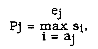
- the poles P i of the filter are calculated from these coefficients, converted to the S plane (log) and conjugate complex pole pairs are sought.
- the poles with a positive frequency are taken into account and sorted according to their respective attenuation (real part).
- the shape and coefficients of the correction function were optimized obtained from the reference data.
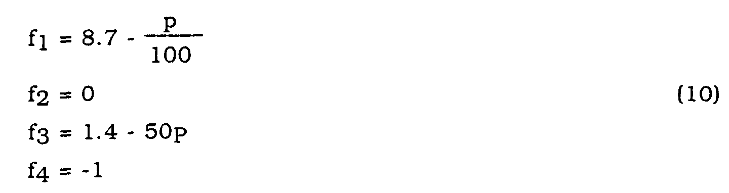
- Functions that are independent of p are only used to shift the value range, so that the material limit for these characteristics is 0.
- Material limit "0" means that all characteristics should deliver values less than 0 for concrete and greater than 0 for bricks.
- a weighted decision is then made using a fuzzy system.
- fuzzy sets are then defined by specifying two parameters t 1 and t 2 .
- the parameter orientation o can be used to determine whether fuzzy sets are to be written which are left 0 (orientation 0) and right 1 (orientation 1) or left 1 or right 0 (orientation -1).
- the threshold value t B depends on the identified drill and is 0.5 for the 6/17 drill considered here as an example. For this specific case, the following parameters must be used in accordance with Table 2 below: characteristic Weight w i Parameter t 1 Parameter t 2 orientation Mean FFT 1 -0.5 0.5 -1 AR spectral damping 2 -1 1 1 AR Coefficient Damping 1 16000 22000 -1 Peak difference 1 0.5 0.5 -1
Landscapes
- Engineering & Computer Science (AREA)
- Life Sciences & Earth Sciences (AREA)
- Geology (AREA)
- Physics & Mathematics (AREA)
- General Life Sciences & Earth Sciences (AREA)
- Mining & Mineral Resources (AREA)
- Environmental & Geological Engineering (AREA)
- Remote Sensing (AREA)
- Mechanical Engineering (AREA)
- Geochemistry & Mineralogy (AREA)
- Acoustics & Sound (AREA)
- Fluid Mechanics (AREA)
- General Physics & Mathematics (AREA)
- Geophysics (AREA)
- Earth Drilling (AREA)
- Drilling And Boring (AREA)
- Investigating Or Analyzing Materials By The Use Of Ultrasonic Waves (AREA)
- Investigating Or Analyzing Materials By The Use Of Magnetic Means (AREA)
Abstract
Description
- Die in der Materialprüfung angewendeten Verfahren sind aufwendig, benötigen eine spezielle Testeinrichtung oder sind nicht automatisierbar und/oder online anwendbar.
- Tastversuche bei Vibrationsanalysen zeigten, daß beispielsweise bei handgeführten Bohrhammergeräten eine Untergrunderkennung aufgrund der Analyse der Gehäusevibration nicht möglich ist. Denkbar wäre die Erkennung über eine Analyse der Werkzeuge - z. B. der Bohrervibrationen. Deren Messung ist aber bei Abbaugeräten der hier in Rede stehenden Art, insbesondere bei Bohrhammergeräten nur sehr schwierig zu realisieren. Die Untergrunderkennung durch Messung der Bohrparameter ist außerdem nur mögich, wenn sämtliche erwähnten Größen bekannt sind, da sie sich stark gegenseitig beeinflussen. Es wird also eine sehr umfangreiche Sensorik benötigt. Nicht zuletzt besteht auch eine große Abhängigkeit vom jeweils verwendeten Werkzeug, also beispielsweise dem Bohrer.
| Erkennung von Untergrund und Werkzeug (Bohrer) durch Messung und Analyse von Longitunalwellen | ||
| Hörschall Messung mit Mikrophon | Körperschall/Stoßwelle Messung mit ME-Sensor Dehnungsmeßstreifen (DMS) Oberflächenwellen | |
| Analyseverfahren | ||
| Zeitbereichsmethoden | FFT-basierte Merkmale | Methoden basierend auf autoregressiven (AR)Modellen |
| - Extremwerte - Energle-Quantil - Schlaglänge/-Abfall - Bandpassfilterung | - Mittelwert - Symmetrie der ersten Eigenfrequenz - Energie - Schwerpunkt | - Dämpfung - Lage der Eigen-frequenzen - Schwerpunkt der Spektren |
- Fig. 1
- verdeutlicht die Prinzipanordnung für die Messung und Erkennung eines zu bearbeitenden Untergrunds gemäß der Erfindung;
- Fig. 2
- veranschaulicht die Darstellung eines Fuzzy-Sets Ai mit der Orientierung 1.; und
- Fig. 3
- zeigt in einem Zeit-Amplitudendiagramm die relative Stärke der Reflexionen einer Stosswelle im Werkzeug.

- 1.
- Mittelung der für die Einzelschläge berechneten Merkmalswerte: ME = Mean (M(Ei))
- 2.
- Berechnung des Merkmals für das im Zeitbereich bestimmte Mittel der Einzelschläge ME = M (Mean(Ei)).





| Merkmal | Gewicht wi | Parameter t1 | Parameter t2 | Orientierung |
| Mean-FFT | 1 | -0,5 | 0,5 | -1 |
| AR-Spectral-Damping | 2 | -1 | 1 | 1 |
| AR-Coefficient-Damping | 1 | 16000 | 22000 | -1 |
| Peakdifferenz | 1 | 0,5 | 0,5 | -1 |
- Lit. [1]:
- Schickert, G., Vorträge und Plakatberichte Internationales Symposium Zerströungsfreie Prüfung im Bauwesen, Deutsche Gesellschaft für Zerstörungsfreie Prüfung e.V., Berlin; 1991.
- Lit. [2]:
- Schickert, G., Wiggenhauser H., International Symposium Non-Destructive Testing in Civil Engineering (NDT-CE), Deutsche Gesellschaft für Zerstörungsfreie Prüfung e. V., Berlin; 1995.
- Lit. [3]:
- Pollitt, M. et al, Lithological Interpretation based on monitored drilling performance paramters, CIM Bulletin, Volume 84, Nr. 985, July 1991, Page 25-29.
- Lit. [4]:
- Uitto V., Verfahren zur Optimierung von schlagenden Gesteinsbohrungen, Patentschrift DE 3 518 370, 1985.
- Lit. [5]:
- Wagner, J., Automatische Qualitäts-Kontroll-Systeme für Dachziegelindustrie, Keramische Zeitschrift, 47. Jahrgang, Ausgabe 6-1995.
- Lit. [6]:
- Jonuscheit, H., Neuronale Netze in der Produktion, Design & Elektronik.
- Lit. [7]:
- Hecker, R., Schröder, P., Nutzung mechanischer u. elektromechanischer Effekte zur Messung elastischer Wellen in Stäben, tm 11/95, R. Oldenburg Verlag.
- Lit. [8]:
- Kammeyer, K., Kroschel K., Digital Signalverarbeitung, Teubner Studienbücher-Elektronik: 1998.
- Lit. [9]:
- Mathworks Inc., Matlab-Manual: System Identifikation Toolbox, Mathworks Inc.: 1998.
- Lit. [10]:
- Mathworks Inc., Matlab-Manual: Signal Processing Toolbox, Mathworks Inc.: 1998
- Lit. [11] :
- Mathworks Inc., Matlab-Manual: Fuzzy Logic Toolbox, Mathworks Inc.: 1998.
- Lit. [12]:
- Kruse, et al, Fuzzy Systeme, Teubner Verlag 1989.
Claims (14)
- Verfahren zur Untersuchung und Identifizierung der Art eines für den Abbau vorgesehenen Untergrunds und zur Bereitstellung mindestens eines Betriebsparameters zur optimierten Voreinstellung eines Abbaugeräts, bei dem vor oder zu Beginn eines Abbauvorgangs eine in einem Werkzeug des Abbaugeräts erzeugte oder induzierte Stoßwelle erfaßt und aus dem so gemessenen Stoßwellen-Signal mindestens ein für den Untergrund charakteristisches Merkmal (M1 bis M4) extrahiert und zur Klassifizierung des Untergrunds mittels eines Algorithmus' ausgewertet wird.
- Verfahren nach Anspruch 1, dadurch gekennzeichnet, daß bei der Klassifizierung des Untergrunds zusätzlich mindestens eine externe auf das Abbaugerät wirkende Kraft (p) berücksichtigt wird.
- Verfahren nach Anspruch 1 oder 2, dadurch gekennzeichnet, daß die Stoßwelle durch einen Sensor (1) erfaßt wird, der auf dem magnetoelastischen Effekt, auf dem Prinzip des Dehnungsmeßstreifens oder auf dem Prinzip der Oberflächenwellenmessung basiert.
- Verfahren nach Anspruch 1 oder 2, dadurch gekennzeichnet, daß die Stoßwelle durch Messung der dadurch verursachten Luftwellen mittels eines Mikrofons erfaßt wird.
- Verfahren nach Anspruch 3, dadurch gekennzeichnet, daß die Longitudinalkomponente der Stoßwelle in einer Werkzeugachse des Abbaugeräts (3) mittels eines Sensors (1) auf der Basis des magnetoelastischen Effekts erfaßt wird.
- Verfahren nach einem der vorstehenden Ansprüche zur Einstellung der Betriebsparameter eines Bohrhammers, bei dem die im jeweils eingesetzten Bohrer (2) induzierte Stoßwelle erfaßt und das Stoßwellensignal algorithmisch analysiert wird zur Gewinnung des mindestens einen, über die Stoßwelle einerseits den Bohrer und andererseits den Untergrund charakterisierenden Merkmals zur On-line-Einstellung mindestens eines der Betriebsparameter "Schlagfrequenz", "Einzelschlagenergier" und/oder "Drehzahl".
- Verfahren nach Anspruch 6, dadurch gekennzeichnet, daß die Extraktion des mindestens einen charakteristischen Merkmals (M1 bis M4) zur Identifizierung des Untergrunds mittels einen Algorithmus' erfolgt, der eine Mehrzahl von einzelnen Bohrhammerschlägen entsprechenden, in Tastwerte digitalisierte Stoßwellensignale (Ei) innerhalb von zueinander hinsichtlich der Schlaganfänge zeitsynchronisierter Fenster analysiert, und daß aus den berechneten Merkmalswerten der einzlenen Bohrhammerschläge durch ein Mittelungsverfahren ein charakterischer Merkmalswert (M1 bis M4) bestimmt wird.
- Verfahren nach Anspruch 6, dadurch gekennzeichnet, daß bei der Mittelung die für die einzelnen Bohrhammerschläge berechneten Merkmalswerte zugrundegelegt werden (ME = Mean (M(Ei)).
- Verfahren nach Anspruch 6, dadurch gekennzeichnet, daß bei Bestimmung der Merkmalswerte das im Zeitbereich bestimmte Mittel der einzelnen Bohrhammerschläge zugrundegelegt wird (ME = Mean (M(Ei)).
- Verfahren nach Anspruch 7, dadurch gekennzeichnet, daß vor der algorithmischen Untergrundidentifizierung eine Werkzeugidentifizierung und entsprechende Voreinstellung von Betriebsparametern des Bohrhammers erfolgt, bei der das gemittelte Spektrum einer festgelegten Anzahl von Tastwerten der Stoßwellensignale der bei einem Meßablauf erfaßten Einzelschlagspektren berechnet und daraus mehrere Eigenfrequenzen, d. h. lokale Maxima in vorgegebenen Bereichen, bestimmt werden, von denen wenigstens zwei zur Bestimmung von für die Betriebsparameter-Voreinstellung erforderlichen Werkzeugparametern mittels eines Fuzzy-Regelalgorithmus' verwendet werden.
- Verfahren nach Anspruch 9, dadurch gekennzeichnet, daß ein Fuzzy-Regelalgorithmus vom Sugeno-Typ verwendet wird.
- Verfahren nach einem der Ansprüche 7 bis 9, dadurch gekennzeichnet, daß die algorithmisch-analytische Untergrundidentifizierung unter Berücksichtigung von mehreren oder allen der folgenden charakteristischen Merkmale (M1 bis M4) erfolgt, von denenein erstes (M1) die im Zeitbereich gemäß dem Mittelungsverfahren nach Anspruch 8 berechnete mittlere Amplitude des energienormierten Spektrums (Fen) eines Einzelschlag-Stoßwellensignals über das berücksichtigte Fenster beinhaltet,ein zweites (M2) unter Berücksichtigung eines werkzeugspezifischen Frequenzbereichs die Maximalamplitude (FAR(fm)) bzw. deren zugehörigen Frequenzwert (fm) aus einer Spektralabschätzung mittels eines autoregressiven Modells eines nur wenige festgelegte Digitalwerte innerhalb des Fenster berücksichtigenden Kurzzeitsignals oder die über den Frequenzbereich bestimmte Dämpfung oder eine lineare Kombinationsfunktion (CO(fm,FAR(fm)) aus der Maximalamplitude (FAR) und dem zugehörigen Frequenzwert (fm) angibt:ein drittes (M3) den minimalen Dämpfungswert eines Pols eines Filters innerhalb eines durch die Werkzeugparameter bestimmten Frequenzintervalls (Δf) darstellt, wobei die Pole aus den Filterkoeffizienten eines assoziierten rekursiven Filters, bestimmt über ein autoregressives Modell eines Einzelschlag-Stoßwellensignals unter Anwendung festgelegter Modellparameter für positive Frequenzwerte, errechnet werden, undein viertes (M4) die Differenz zweier Maxima gleichen Vorzeichens des Stoßwellensignals im Zeitbereich innerhalb eines Suchintervalls angibt, und daß
die mehreren oder alle Merkmale (M1 bis M4) bei der Entscheidung zur Materialbestimmung des Untergrunds über ein Fuzzy-Inteferenzsystem mit jeweils zugeordneter Gewichtung bewertet werden. - Verfahren nach Anspruch 9, dadurch gekennzeichnet, daß die Merkmale vor einer Bewertung über das Fuzzy-Interferenzsystem jeweils um einen von der Anpreßkraft (p) und/oder dem jeweiligen Werkzeug (2) abhängigen Faktor korrigiert werden.
- Einrichtung an oder in Zuordnung zu einem Gerät (3) zum Abbau eines Untergrunds zur Untersuchung und Identifizierung der Art des abzubauenden Untergrunds mit einem eine Stoßwelle im Abbauwerkzeug (2) des Geräts erfassenden Sensor (1) und einer elektronischen Prozessoreinheit, welche das von dem Sensor gelieferte Stoßwellensignal gemäß einem in wenigstens einem der vorstehenden Ansprüche definierten Verfahren auswertet.
Applications Claiming Priority (2)
| Application Number | Priority Date | Filing Date | Title |
|---|---|---|---|
| DE19960824A DE19960824C2 (de) | 1999-12-16 | 1999-12-16 | Verfahren und Einrichtung zur Untersuchung und Identifizierung der Art eines Untergrunds |
| DE19960824 | 1999-12-16 |
Publications (2)
| Publication Number | Publication Date |
|---|---|
| EP1109034A1 true EP1109034A1 (de) | 2001-06-20 |
| EP1109034B1 EP1109034B1 (de) | 2009-01-28 |
Family
ID=7932973
Family Applications (1)
| Application Number | Title | Priority Date | Filing Date |
|---|---|---|---|
| EP00811161A Expired - Lifetime EP1109034B1 (de) | 1999-12-16 | 2000-12-07 | Verfahren und Einrichtung zur Untersuchung und Identifizierung der Art eines Untergrundes |
Country Status (5)
| Country | Link |
|---|---|
| US (1) | US6640205B2 (de) |
| EP (1) | EP1109034B1 (de) |
| JP (1) | JP4550266B2 (de) |
| CN (1) | CN100350130C (de) |
| DE (2) | DE19960824C2 (de) |
Cited By (5)
| Publication number | Priority date | Publication date | Assignee | Title |
|---|---|---|---|---|
| US7318489B2 (en) | 2004-01-23 | 2008-01-15 | Shell Oil Company | Hydraulic motor arrangement and method of operating a hydraulic motor |
| US7748446B2 (en) | 2004-01-23 | 2010-07-06 | Shell Oil Company | Seismic source and method of generating a seismic wave in a formation |
| EP2213420A1 (de) * | 2009-01-30 | 2010-08-04 | HILTI Aktiengesellschaft | Steuerungsverfahren und Handwerkzeugmaschine |
| WO2011038953A1 (de) * | 2009-10-01 | 2011-04-07 | Robert Bosch Gmbh | Werkzeugmaschine, insbesondere handgehaltene werkzeugmaschine |
| WO2022043151A1 (de) * | 2020-08-26 | 2022-03-03 | Hilti Aktiengesellschaft | Werkzeugmaschine zur bearbeitung eines untergrunds und verfahren zur analyse einer zusammensetzung des untergrunds |
Families Citing this family (25)
| Publication number | Priority date | Publication date | Assignee | Title |
|---|---|---|---|---|
| WO2003096007A1 (en) * | 2002-05-08 | 2003-11-20 | Sekisui Chemical Co., Ltd. | Method and equipment for inspecting reinforced concrete pipe |
| FI120559B (fi) * | 2006-01-17 | 2009-11-30 | Sandvik Mining & Constr Oy | Menetelmä jännitysaallon mittaamiseksi, mittauslaite ja kallion rikkomislaite |
| DE102007005560B4 (de) * | 2007-01-24 | 2009-12-03 | Bernhard Sänger | Verfahren zum Betrieb einer Tunnelbohrmaschine, Verfahren zum Erkennen von geologischen Strukturen sowie Tunnelbohrmaschine |
| DE102008055057A1 (de) * | 2008-12-22 | 2010-06-24 | Robert Bosch Gmbh | Werkzeugmaschine, insbesondere handgehaltene Werkzeugmaschine |
| US20100329081A1 (en) * | 2009-06-26 | 2010-12-30 | Eric Sullivan | Method for non-destructively evaluating rotary earth boring drill components and determining fitness-for-use of the same |
| DE102012208870A1 (de) * | 2012-05-25 | 2013-11-28 | Robert Bosch Gmbh | Schlagwerkeinheit |
| GB201317883D0 (en) * | 2013-10-09 | 2013-11-20 | Iti Scotland Ltd | Control method |
| GB201318020D0 (en) | 2013-10-11 | 2013-11-27 | Iti Scotland Ltd | Drilling apparatus |
| EP2868437A1 (de) * | 2013-10-29 | 2015-05-06 | HILTI Aktiengesellschaft | Handgeführtes oder halbstationäres Werkzeuggerät oder Arbeitsgerät |
| EP3181303A1 (de) * | 2015-12-14 | 2017-06-21 | HILTI Aktiengesellschaft | Steuerungsverfahren und handwerkzeugmaschine |
| SE540205C2 (sv) | 2016-06-17 | 2018-05-02 | Epiroc Rock Drills Ab | System och förfarande för att bedöma effektivitet hos en borrningsprocess |
| DE102016214699A1 (de) * | 2016-08-08 | 2018-02-08 | Sauer Gmbh | Verfahren und Vorrichtung zur Bearbeitung eines Werkstücks an einer numerisch gesteuerten Werkzeugmaschine |
| EP3311956A1 (de) | 2016-10-20 | 2018-04-25 | HILTI Aktiengesellschaft | Steuerungsverfahren und bohrlochspülmodul |
| EP3311951A1 (de) | 2016-10-20 | 2018-04-25 | HILTI Aktiengesellschaft | Steuerungsverfahren und staubabsaugmodul |
| ES2855140T3 (es) | 2018-03-08 | 2021-09-23 | Stihl Ag & Co Kg Andreas | Procedimiento para la operación dependiente del tipo, de una unidad eléctrica de accionamiento y un sistema |
| DE102019200527A1 (de) * | 2019-01-17 | 2020-07-23 | Robert Bosch Gmbh | Handwerkzeugmaschine |
| SE543372C2 (sv) | 2019-03-29 | 2020-12-22 | Epiroc Rock Drills Ab | Borrmaskin och metod för att styra en borrningsprocess hos en borrmaskin |
| EP3854532A1 (de) * | 2019-08-19 | 2021-07-28 | Hilti Aktiengesellschaft | Handwerkzeugmaschine, werkzeug und handwerkzeugmaschinensystem mit bestimmtem drehzahl-schlagleistungs-verhältnis |
| DE102020205145A1 (de) | 2020-04-23 | 2021-10-28 | Robert Bosch Gesellschaft mit beschränkter Haftung | Verfahren zum Ermitteln einer Materialinformation |
| CN111636859B (zh) * | 2020-07-09 | 2022-08-16 | 中煤科工集团重庆研究院有限公司 | 基于微破裂波检测的煤岩随钻自识别方法 |
| CN112706129B (zh) * | 2020-11-13 | 2021-08-24 | 交通运输部公路科学研究所 | 一种基于声波信号控制的冲击钻 |
| CN112692792B (zh) * | 2020-11-13 | 2021-08-13 | 交通运输部公路科学研究所 | 一种基于振动信号控制的冲击钻 |
| AU2021408909A1 (en) | 2020-12-21 | 2023-06-15 | Epiroc Rock Drills Aktiebolag | Method and system for optimising a drilling parameter during an ongoing drilling process |
| EP4264001B1 (de) | 2020-12-21 | 2024-09-25 | Epiroc Rock Drills Aktiebolag | Verfahren und system zur detektion des zustandes einer bohrstrangverbindung |
| FI20247015A1 (en) * | 2024-02-01 | 2025-08-02 | Lekatech Oy | An electric percussion device and a method for controlling the same |
Citations (8)
| Publication number | Priority date | Publication date | Assignee | Title |
|---|---|---|---|---|
| US3464503A (en) * | 1968-06-25 | 1969-09-02 | Black & Decker Mfg Co | Measuring device for impact tool |
| DE3518370A1 (de) | 1984-06-12 | 1985-12-12 | Osakeyhtiö Tampella AB, Tampere | Verfahren zur optimierung der gesteinsbohrung |
| US5289885A (en) * | 1992-01-23 | 1994-03-01 | Makita Corporation | Tightening tool |
| DE4334933A1 (de) * | 1993-10-13 | 1995-04-20 | Fraunhofer Ges Forschung | Verfahren und Vorrichtung zum zwangsweisen Abschalten von handgeführten Arbeitsmitteln |
| WO1996025881A1 (en) * | 1995-02-22 | 1996-08-29 | Groenningsaeter Aage | Method for ultrasound guidance during clinical procedures |
| EP0771619A2 (de) * | 1995-11-02 | 1997-05-07 | Robert Bosch Gmbh | Verfahren zum Unterbrechen der Antriebstätigkeit einer Handwerkzeugmaschine, sowie nach diesen Verfahren arbeitende Handwerkzeugmaschine |
| WO1998001736A1 (en) * | 1996-07-04 | 1998-01-15 | P.B. Sensortechnology & Consultancy | Method and device for measuring resilience |
| GB2333155A (en) * | 1998-01-07 | 1999-07-14 | Anadrill Int Sa | Acoustic measurement while drilling system using compressional waves reflected from within formation |
Family Cites Families (4)
| Publication number | Priority date | Publication date | Assignee | Title |
|---|---|---|---|---|
| SE8703418D0 (sv) * | 1987-09-03 | 1987-09-03 | Olsson Konsult Ab | Anordning for beroringsfri uppmetning av pakenningar i en stangformig kropp |
| US5170852A (en) | 1992-05-11 | 1992-12-15 | Nitto Seiko Co., Ltd. | Automatic screw fastening machine |
| US5496093A (en) * | 1994-12-23 | 1996-03-05 | Csir & Sasol Mining Proprietary Ltd. | Operating a continuous miner |
| US6085121A (en) * | 1997-09-22 | 2000-07-04 | Design & Manufacturing Solutions, Inc. | Device and method for recommending dynamically preferred speeds for machining |
-
1999
- 1999-12-16 DE DE19960824A patent/DE19960824C2/de not_active Expired - Fee Related
-
2000
- 2000-12-07 DE DE50015541T patent/DE50015541D1/de not_active Expired - Lifetime
- 2000-12-07 EP EP00811161A patent/EP1109034B1/de not_active Expired - Lifetime
- 2000-12-11 CN CNB001355988A patent/CN100350130C/zh not_active Expired - Fee Related
- 2000-12-12 US US09/735,340 patent/US6640205B2/en not_active Expired - Lifetime
- 2000-12-18 JP JP2000383723A patent/JP4550266B2/ja not_active Expired - Fee Related
Patent Citations (8)
| Publication number | Priority date | Publication date | Assignee | Title |
|---|---|---|---|---|
| US3464503A (en) * | 1968-06-25 | 1969-09-02 | Black & Decker Mfg Co | Measuring device for impact tool |
| DE3518370A1 (de) | 1984-06-12 | 1985-12-12 | Osakeyhtiö Tampella AB, Tampere | Verfahren zur optimierung der gesteinsbohrung |
| US5289885A (en) * | 1992-01-23 | 1994-03-01 | Makita Corporation | Tightening tool |
| DE4334933A1 (de) * | 1993-10-13 | 1995-04-20 | Fraunhofer Ges Forschung | Verfahren und Vorrichtung zum zwangsweisen Abschalten von handgeführten Arbeitsmitteln |
| WO1996025881A1 (en) * | 1995-02-22 | 1996-08-29 | Groenningsaeter Aage | Method for ultrasound guidance during clinical procedures |
| EP0771619A2 (de) * | 1995-11-02 | 1997-05-07 | Robert Bosch Gmbh | Verfahren zum Unterbrechen der Antriebstätigkeit einer Handwerkzeugmaschine, sowie nach diesen Verfahren arbeitende Handwerkzeugmaschine |
| WO1998001736A1 (en) * | 1996-07-04 | 1998-01-15 | P.B. Sensortechnology & Consultancy | Method and device for measuring resilience |
| GB2333155A (en) * | 1998-01-07 | 1999-07-14 | Anadrill Int Sa | Acoustic measurement while drilling system using compressional waves reflected from within formation |
Cited By (6)
| Publication number | Priority date | Publication date | Assignee | Title |
|---|---|---|---|---|
| US7318489B2 (en) | 2004-01-23 | 2008-01-15 | Shell Oil Company | Hydraulic motor arrangement and method of operating a hydraulic motor |
| US7748446B2 (en) | 2004-01-23 | 2010-07-06 | Shell Oil Company | Seismic source and method of generating a seismic wave in a formation |
| EP2213420A1 (de) * | 2009-01-30 | 2010-08-04 | HILTI Aktiengesellschaft | Steuerungsverfahren und Handwerkzeugmaschine |
| US8333251B2 (en) | 2009-01-30 | 2012-12-18 | Hilti Aktiengesellschaft | Control method and hand-held power tool |
| WO2011038953A1 (de) * | 2009-10-01 | 2011-04-07 | Robert Bosch Gmbh | Werkzeugmaschine, insbesondere handgehaltene werkzeugmaschine |
| WO2022043151A1 (de) * | 2020-08-26 | 2022-03-03 | Hilti Aktiengesellschaft | Werkzeugmaschine zur bearbeitung eines untergrunds und verfahren zur analyse einer zusammensetzung des untergrunds |
Also Published As
| Publication number | Publication date |
|---|---|
| US20020050168A1 (en) | 2002-05-02 |
| DE19960824C2 (de) | 2003-08-21 |
| EP1109034B1 (de) | 2009-01-28 |
| JP4550266B2 (ja) | 2010-09-22 |
| JP2001228125A (ja) | 2001-08-24 |
| CN100350130C (zh) | 2007-11-21 |
| DE50015541D1 (de) | 2009-03-19 |
| DE19960824A1 (de) | 2001-06-28 |
| CN1309229A (zh) | 2001-08-22 |
| US6640205B2 (en) | 2003-10-28 |
Similar Documents
| Publication | Publication Date | Title |
|---|---|---|
| EP1109034B1 (de) | Verfahren und Einrichtung zur Untersuchung und Identifizierung der Art eines Untergrundes | |
| DE112010001558B4 (de) | Verfahren und Vorrichtung zur Ratterunterdrückung bei Arbeitsmaschinen | |
| DE102018108780B4 (de) | Bearbeitungsflächenqualitätsbewertungsvorrichtung | |
| EP2204660B1 (de) | Vorrichtung und verfahren zum bestimmen von teilentladungen an einer elektrischen komponente | |
| DE102014000477A1 (de) | Vorrichtung und Verfahren zum Messen von Befestigungskräften | |
| WO2018050499A1 (de) | Verfahren und vorrichtung zur bestimmung und/oder überwachung des zustandes eines transformatorenöls | |
| DE60117049T2 (de) | Maschinenzustandsüberwachungsvorrichtung mit steuerungseinrichtung | |
| DE112020006911T5 (de) | Datenerzeugungsvorrichtung, System für maschinelles Lernen und Bearbeitungszustands-Schätzvorrichtung | |
| DE102011055523A1 (de) | Verfahren und Vorrichtung zur Schwingungsanalyse von Anlagen oder Maschinenelementen | |
| EP1177438A2 (de) | Vorrichtung zur materialuntersuchung | |
| DE69818380T2 (de) | Verfahren zur Überwachung eines mit Beschleunigungssensoren versehenen Planetengetriebes in einem Fortbewegungsmittel, insbesondere in einem Helikopter | |
| EP3375571B1 (de) | Sensorik für einen elektroschrauber zur klassifizierung von schraubvorgängen mittels eines magnetfeldsensors | |
| Al-Bugharbee et al. | A new methodology for fault detection in rolling element bearings using singular spectrum analysis | |
| EP2317308B1 (de) | Vorrichtung und verfahren zum überprüfen eines bauteils auf schäden | |
| EP3798361A1 (de) | Überwachungsvorrichtung für einen gleitschalungsfertiger zur überwachung der verdichtung von beton und verfahren zur überwachung der verdichtung von beton während des betriebs eines gleitschalungsfertigers | |
| EP4172579B1 (de) | Verfahren für eine überwachung wenigstens einer durch eine rotierende maschine angetriebenen arbeitsmaschine | |
| EP3792709A1 (de) | Analysevorrichtung für betriebsgeräusche einer werkzeugmaschine | |
| EP1197415A2 (de) | Verfahren und Vorrichtung zur Erkennung eines schadhaften Wälzlagers eines Schienenfahrzeuges | |
| EP1415132B1 (de) | Spektrale bewertung eines prüfobjekts | |
| DE102010005525A1 (de) | Verfahren zur Zustandsüberwachung einer Maschine und Überwachungseinrichtung hierfür | |
| DE102017112776B4 (de) | Verfahren und Vorrichtung zur dynamischen Belastungsprüfung | |
| DE102014003844A1 (de) | Verfahren zum Überprüfen eines mindestens zwei Schneiden aufweisenden Werkzeugs | |
| EP2240835B1 (de) | Verfahren zur bestimmung der bearbeitungsgüte von bauteilen insbesondere bei spanender bearbeitung durch nc maschinen | |
| EP3959498B1 (de) | Akustische analyse eines zustands einer maschine | |
| EP3396404B1 (de) | Verfahren zur lageerkennung von objekten |
Legal Events
| Date | Code | Title | Description |
|---|---|---|---|
| PUAI | Public reference made under article 153(3) epc to a published international application that has entered the european phase |
Free format text: ORIGINAL CODE: 0009012 |
|
| AK | Designated contracting states |
Kind code of ref document: A1 Designated state(s): AT BE CH CY DE DK ES FI FR GB GR IE IT LI LU MC NL PT SE TR |
|
| AX | Request for extension of the european patent |
Free format text: AL;LT;LV;MK;RO;SI |
|
| 17P | Request for examination filed |
Effective date: 20011220 |
|
| AKX | Designation fees paid |
Free format text: CH DE FR GB LI NL SE |
|
| 17Q | First examination report despatched |
Effective date: 20071214 |
|
| GRAP | Despatch of communication of intention to grant a patent |
Free format text: ORIGINAL CODE: EPIDOSNIGR1 |
|
| GRAS | Grant fee paid |
Free format text: ORIGINAL CODE: EPIDOSNIGR3 |
|
| GRAA | (expected) grant |
Free format text: ORIGINAL CODE: 0009210 |
|
| AK | Designated contracting states |
Kind code of ref document: B1 Designated state(s): CH DE FR GB LI NL SE |
|
| REG | Reference to a national code |
Ref country code: GB Ref legal event code: FG4D Free format text: NOT ENGLISH |
|
| REG | Reference to a national code |
Ref country code: CH Ref legal event code: EP |
|
| REG | Reference to a national code |
Ref country code: SE Ref legal event code: TRGR |
|
| REF | Corresponds to: |
Ref document number: 50015541 Country of ref document: DE Date of ref document: 20090319 Kind code of ref document: P |
|
| PLBE | No opposition filed within time limit |
Free format text: ORIGINAL CODE: 0009261 |
|
| STAA | Information on the status of an ep patent application or granted ep patent |
Free format text: STATUS: NO OPPOSITION FILED WITHIN TIME LIMIT |
|
| 26N | No opposition filed |
Effective date: 20091029 |
|
| PGFP | Annual fee paid to national office [announced via postgrant information from national office to epo] |
Ref country code: CH Payment date: 20131212 Year of fee payment: 14 Ref country code: SE Payment date: 20131211 Year of fee payment: 14 Ref country code: GB Payment date: 20131204 Year of fee payment: 14 |
|
| PGFP | Annual fee paid to national office [announced via postgrant information from national office to epo] |
Ref country code: FR Payment date: 20131209 Year of fee payment: 14 Ref country code: NL Payment date: 20131210 Year of fee payment: 14 |
|
| REG | Reference to a national code |
Ref country code: NL Ref legal event code: V1 Effective date: 20150701 |
|
| REG | Reference to a national code |
Ref country code: NL Ref legal event code: V1 Effective date: 20150701 |
|
| PG25 | Lapsed in a contracting state [announced via postgrant information from national office to epo] |
Ref country code: SE Free format text: LAPSE BECAUSE OF NON-PAYMENT OF DUE FEES Effective date: 20141208 |
|
| REG | Reference to a national code |
Ref country code: CH Ref legal event code: PL |
|
| REG | Reference to a national code |
Ref country code: SE Ref legal event code: EUG |
|
| GBPC | Gb: european patent ceased through non-payment of renewal fee |
Effective date: 20141207 |
|
| REG | Reference to a national code |
Ref country code: FR Ref legal event code: ST Effective date: 20150831 |
|
| PG25 | Lapsed in a contracting state [announced via postgrant information from national office to epo] |
Ref country code: NL Free format text: LAPSE BECAUSE OF NON-PAYMENT OF DUE FEES Effective date: 20150701 |
|
| PG25 | Lapsed in a contracting state [announced via postgrant information from national office to epo] |
Ref country code: CH Free format text: LAPSE BECAUSE OF NON-PAYMENT OF DUE FEES Effective date: 20141231 Ref country code: GB Free format text: LAPSE BECAUSE OF NON-PAYMENT OF DUE FEES Effective date: 20141207 Ref country code: LI Free format text: LAPSE BECAUSE OF NON-PAYMENT OF DUE FEES Effective date: 20141231 |
|
| PG25 | Lapsed in a contracting state [announced via postgrant information from national office to epo] |
Ref country code: FR Free format text: LAPSE BECAUSE OF NON-PAYMENT OF DUE FEES Effective date: 20141231 |
|
| PGFP | Annual fee paid to national office [announced via postgrant information from national office to epo] |
Ref country code: DE Payment date: 20191210 Year of fee payment: 20 |
|
| REG | Reference to a national code |
Ref country code: DE Ref legal event code: R071 Ref document number: 50015541 Country of ref document: DE |