EP1109233B1 - Hakenförmiger piezoelektrischer Antrieb - Google Patents
Hakenförmiger piezoelektrischer Antrieb Download PDFInfo
- Publication number
- EP1109233B1 EP1109233B1 EP99830726A EP99830726A EP1109233B1 EP 1109233 B1 EP1109233 B1 EP 1109233B1 EP 99830726 A EP99830726 A EP 99830726A EP 99830726 A EP99830726 A EP 99830726A EP 1109233 B1 EP1109233 B1 EP 1109233B1
- Authority
- EP
- European Patent Office
- Prior art keywords
- actuator
- actuator according
- sheet
- piezoelectric elements
- piezoelectric
- Prior art date
- Legal status (The legal status is an assumption and is not a legal conclusion. Google has not performed a legal analysis and makes no representation as to the accuracy of the status listed.)
- Expired - Lifetime
Links
Images

Classifications
-
- H—ELECTRICITY
- H02—GENERATION; CONVERSION OR DISTRIBUTION OF ELECTRIC POWER
- H02N—ELECTRIC MACHINES NOT OTHERWISE PROVIDED FOR
- H02N2/00—Electric machines in general using piezoelectric effect, electrostriction or magnetostriction
- H02N2/0005—Electric machines in general using piezoelectric effect, electrostriction or magnetostriction producing non-specific motion; Details common to machines covered by H02N2/02 - H02N2/16
- H02N2/001—Driving devices, e.g. vibrators
- H02N2/0015—Driving devices, e.g. vibrators using only bending modes
-
- H—ELECTRICITY
- H02—GENERATION; CONVERSION OR DISTRIBUTION OF ELECTRIC POWER
- H02N—ELECTRIC MACHINES NOT OTHERWISE PROVIDED FOR
- H02N2/00—Electric machines in general using piezoelectric effect, electrostriction or magnetostriction
- H02N2/02—Electric machines in general using piezoelectric effect, electrostriction or magnetostriction producing linear motion, e.g. actuators; Linear positioners ; Linear motors
- H02N2/026—Electric machines in general using piezoelectric effect, electrostriction or magnetostriction producing linear motion, e.g. actuators; Linear positioners ; Linear motors by pressing one or more vibrators against the driven body
-
- H—ELECTRICITY
- H10—SEMICONDUCTOR DEVICES; ELECTRIC SOLID-STATE DEVICES NOT OTHERWISE PROVIDED FOR
- H10N—ELECTRIC SOLID-STATE DEVICES NOT OTHERWISE PROVIDED FOR
- H10N30/00—Piezoelectric or electrostrictive devices
- H10N30/20—Piezoelectric or electrostrictive devices with electrical input and mechanical output, e.g. functioning as actuators or vibrators
- H10N30/204—Piezoelectric or electrostrictive devices with electrical input and mechanical output, e.g. functioning as actuators or vibrators using bending displacement, e.g. unimorph, bimorph or multimorph cantilever or membrane benders
- H10N30/2041—Beam type
- H10N30/2042—Cantilevers, i.e. having one fixed end
- H10N30/2044—Cantilevers, i.e. having one fixed end having multiple segments mechanically connected in series, e.g. zig-zag type
Definitions
- the present invention relates to the field of piezoelectric actuators and has the object of providing an actuator of this type which is simple and of relatively low cost, as well as of reduced dimensions while being at the same time adapted to be used efficiently in various applications in micro-mechanics.
- the invention provides a piezoelectric actuator, comprising a metal sheet including a first base portion and a second portion inclined substantially at 90 degrees relative to the first portion and ending with a free end edge acting as a driving member, said actuator further comprising a pair of piezoelectric elements respectively applied to the two above mentioned sheet portions, and electric supply means adapted to supply an electric voltage separately to the two above mentioned piezoelectric elements.
- the above mentioned electric supply means are adapted to supply the two piezoelectric elements with two alternated voltages which are 90 degrees out of phase relative to each other.
- the two piezoelectric elements are cyclically deflected giving rise to an hellipsoidal motion of the end free edge of the sheet which can be exploited to repeatedly transmit a force by contact friction in the direction of the major axis of the hellipse to a driven member which is in contact with said end edge.
- the above mentioned sheet is obtained by forming a U-shaped cut in a base plate and bending the sheet which is thus obtained by this cutting at mid length thereof by 90 degrees.
- the two piezoelectric elements may be constituted by sheets applied by screen-printing.
- a plurality of sheets are formed by cutting which are bent in the above described manner, so as to provide a plurality of actuators which are arranged side-by-side and/or in line with each other.
- reference numeral 1 designates a steel sheet having a thickness in the order of hundredths of millimeter, in which a U-shaped cut 2 is formed to define a sheet 3 having a first base portion 4 which is adapted to be deflected with respect to one side 5 connected to the base plate 1, and a second portion 6 which is bent by about 90 degrees out of the plane of the base plate 1 at an intermediate bending edge 7.
- two piezoelectric elements 8, 9 are applied, such as by screen-printing, which elements are in form of sheets each having a thickness between 10 and 30 micrometers. It is clearly apparent that the application of the two piezoelectric layers 8, 9 may be obtained according to any known technology, such as by dipping. According to the invention, preferably the twopieroelectric layers are applied before cut 2 is formed.
- the two piezoelectric elements 8, 9 have respectively electrodes 8, 9 which are connected to electric supply means 10.
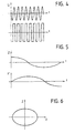
- the two piezelectric elements 8, 9 are supplied with an alternated electric voltage, of sinusoidal or square shape, as shown in figure 4.
- In the supply frequence depends upon the dimensions of the actuator, which may vary from some fraction of millimeter to some millimeters.
- the two piezoelectric elements are supplied by the same signal out of phase by 90 degrees.
- the upper portion of the diagram of figure 5 shows the movement of the edge 7 in the direction of the Z axis, whereas the lower part shows the movement of the free end edge of sheet 6 (designated by 11) in the direction X', in a reference system (X', Y', Z') having its origin at point 7 and its axes parallel to those of the fixed reference system (X, Y, Z).
- the composition of the two movements causes a hellipsoidal movement of the end free edge 11 of the structure, as shown in figure 6 in the (X, Y, Z) reference system. Therefore, if the end free edge 11 is in contact by friction with the lower surface of a driven element which is to be moved in the X direction, the free edge 11 repeatedly applies a force to the driven body.
- the edge 11 is provided with a coating of a material having a high friction coefficient.
- the two piezoelectric elements 8, 9 behave as two flexures, determining an oscillation of points 7, 11, according to what has been described in the foregoing.
- the direction of this movement is rightward or leftward (with reference to figure 2) depending upon the two signals supplied to the two piezoelectric elements 8, 9 being out of phase by +90 degrees or -90 degrees.
- this cut 2 may be different from that shown in the drawings.
- this cut may have a rectangular shape similar to that shown in figure 1, but with a portion connected to the base plate arranged on one side of the two piezoelectric elements 8, 9, rather than on one end.
- this cut may have a hellipsoidal shape in plan view, rather than rectangular, or it may have a thinner portion between one piezoelectric element and the other.
- sensor means of any type may be provided, such as of optical type, to detect the position of the driven body and thus to enable a closed loop control of the position of this body with the aid of the actuator according to the invention.
- sensor means of any type may be provided, such as of optical type, to detect the position of the driven body and thus to enable a closed loop control of the position of this body with the aid of the actuator according to the invention.
Landscapes
- General Electrical Machinery Utilizing Piezoelectricity, Electrostriction Or Magnetostriction (AREA)
Claims (10)
- Piezoelektrischer Aktuator, welcher ein Metallblatt (3) aufweist, das einen ersten Basisabschnitt (4) und einen zweiten Abschnitt (6) aufweist, der im Wesentlichen um 90 Grad bezüglich dem ersten Abschnitt (4) geneigt ist und mit einer freien Endkante (11) endet, welche als angetriebenes Element wirkt, wobei der Aktuator weiter ein Paar von piezoelektrischen Elementen (8, 9) umfasst, die an den zwei oben genannten Abschnitten (8, 9,) des Blattes (3) angebracht sind, und elektrische Versorgungsmittel (10) zur Zufuhr von elektrischer Spannung einzeln zu den piezoelektrischen Elementen (8, 9).
- Aktuator gemäß Anspruch 1, dadurch gekennzeichnet, dass die elektrischen Versorgungsmittel (10) angepasst sind, um eine wechselnde elektrische Spannung jedem der piezoelektrischen Elemente (8, 9) zuzuführen, wobei die Spannung bezüglich der zu dem anderen piezoelektrischen Element zugeführten Spannung 90 Grad außerphasig ist.
- Aktuator gemäß Anspruch 1, dadurch gekennzeichnet, dass das Blatt (3) aus Stahl hergestellt ist und durch Ausbilden eines Schnittes (2) in der Grundplatte (1) erhalten wird.
- Aktuator gemäß Anspruch 3, dadurch gekennzeichnet, dass der Schnitt (2) U-förmig ist.
- Aktuator gemäß Anspruch 1, dadurch gekennzeichnet, dass eine Mehrzahl von Betätigungsblättern (3) in der gleichen Grundplatte (1) ausgebildet sind und Seite an Seite und/oder in einer Reihe miteinander angeordnet sind, entsprechend gleichen oder unterschiedlichen Orientierungen, um die Kraft des Aktuators und/oder die damit verbundenen Freiheitsgrade in der Bewegung zu erhöhen.
- Aktuator gemäß Anspruch 1, dadurch gekennzeichnet, dass das Blatt (3) aus Stahl hergestellt ist.
- Aktuator gemäß Anspruch 1, dadurch gekennzeichnet, dass das Blatt (3) eine Dicke in der Größenordnung von hundertstel Millimetern aufweist.
- Aktuator gemäß Anspruch 1, dadurch gekennzeichnet, dass die piezoelektrischen Elemente (8, 9) Blätter sind, welche eine Dicke von 10 bis 30 Mikron aufweisen.
- Aktuator gemäß Anspruch 8, dadurch gekennzeichnet, dass die piezoelektrischen Elemente (8, 9) mittels Siebbedruckung aufgebracht werden.
- Aktuator gemäß Anspruch 1, dadurch gekennzeichnet, dass die freie Endkante (11) des Aktuators mit einer Beschichtung eines Materials versehen ist, welches einen hohen Reibungskoeffizienten aufweist.
Priority Applications (3)
| Application Number | Priority Date | Filing Date | Title |
|---|---|---|---|
| EP99830726A EP1109233B1 (de) | 1999-11-25 | 1999-11-25 | Hakenförmiger piezoelektrischer Antrieb |
| DE69900855T DE69900855T2 (de) | 1999-11-25 | 1999-11-25 | Hakenförmiger piezoelektrischer Antrieb |
| ES99830726T ES2169939T3 (es) | 1999-11-25 | 1999-11-25 | Accionador piezoelectrico en forma de gancho. |
Applications Claiming Priority (1)
| Application Number | Priority Date | Filing Date | Title |
|---|---|---|---|
| EP99830726A EP1109233B1 (de) | 1999-11-25 | 1999-11-25 | Hakenförmiger piezoelektrischer Antrieb |
Publications (2)
| Publication Number | Publication Date |
|---|---|
| EP1109233A1 EP1109233A1 (de) | 2001-06-20 |
| EP1109233B1 true EP1109233B1 (de) | 2002-01-30 |
Family
ID=8243681
Family Applications (1)
| Application Number | Title | Priority Date | Filing Date |
|---|---|---|---|
| EP99830726A Expired - Lifetime EP1109233B1 (de) | 1999-11-25 | 1999-11-25 | Hakenförmiger piezoelektrischer Antrieb |
Country Status (3)
| Country | Link |
|---|---|
| EP (1) | EP1109233B1 (de) |
| DE (1) | DE69900855T2 (de) |
| ES (1) | ES2169939T3 (de) |
Families Citing this family (2)
| Publication number | Priority date | Publication date | Assignee | Title |
|---|---|---|---|---|
| ATE467238T1 (de) | 2005-04-28 | 2010-05-15 | Brother Ind Ltd | Verfahren zur herstellung eines piezoelektrischen aktors |
| CN117208196A (zh) * | 2023-10-07 | 2023-12-12 | 南京航空航天大学 | 一种自适应桨叶及飞机 |
Family Cites Families (2)
| Publication number | Priority date | Publication date | Assignee | Title |
|---|---|---|---|---|
| JP2651462B2 (ja) * | 1988-03-10 | 1997-09-10 | セイコー電子工業株式会社 | 圧電アクチュエータ |
| DE4435882C2 (de) * | 1994-10-07 | 1996-10-02 | Bosch Gmbh Robert | Ultraschallmotor |
-
1999
- 1999-11-25 EP EP99830726A patent/EP1109233B1/de not_active Expired - Lifetime
- 1999-11-25 ES ES99830726T patent/ES2169939T3/es not_active Expired - Lifetime
- 1999-11-25 DE DE69900855T patent/DE69900855T2/de not_active Expired - Lifetime
Also Published As
| Publication number | Publication date |
|---|---|
| ES2169939T3 (es) | 2002-07-16 |
| DE69900855D1 (de) | 2002-03-14 |
| DE69900855T2 (de) | 2002-09-05 |
| EP1109233A1 (de) | 2001-06-20 |
Similar Documents
| Publication | Publication Date | Title |
|---|---|---|
| US4580073A (en) | Vibration wave motor with plural projection vibrator | |
| US7091647B2 (en) | Micromechanical device having braking mechanism | |
| US7786648B2 (en) | Semi-resonant driving systems and methods thereof | |
| US5633554A (en) | Piezoelectric linear actuator | |
| EP1273094A2 (de) | Mehrschichtige selbstjustierte vertikale kammförmige elektrostatische antriebe und herstellungsverfahren | |
| KR20010078306A (ko) | 교번하는 작용 부분과 대향 부분의 서펜타인 배치를구비하는 액튜에이터 및, 관련 방법 | |
| JP2010134432A (ja) | マイクロメカニカル素子、マイクロメカニカル素子を監視するためのセンサ、マイクロメカニカル素子を操作する方法、マイクロメカニカル素子の監視方法、これらの方法を実施するためのプログラムコードを含むコンピュータプログラムおよびマイクロメカニカル素子の機械的固有共振に影響を与える方法 | |
| US7015624B1 (en) | Non-uniform thickness electroactive device | |
| US20050052723A1 (en) | Electrostatic comb drive actuator, and optical controller using the electrostatic comb drive actuator | |
| KR19990026649A (ko) | 마이크로파 진동구조물과 그 공진주파수 조절방법및 이를 이용 한 마이크로 엑츄에이터 | |
| KR970072620A (ko) | 고동적 압전 구동장치 | |
| KR20210040384A (ko) | 압전 구동부, 특히 차량 요소용 자동 액추에이터 요소로서 압전 구동부 | |
| CN109314474B (zh) | 超声波电机 | |
| JPH11195820A (ja) | 圧電アクチエータ | |
| US11114954B2 (en) | Ultrasonic motor having generators formed of cooperating and spaced apart first and second sub-generators | |
| KR930009211A (ko) | 초음파 모우터 | |
| EP0416884B1 (de) | Vibrationswellenbetriebener Motor | |
| US6448694B2 (en) | Actuator and driving method thereof | |
| EP1109233A1 (de) | Hakenförmiger piezoelektrischer Antrieb | |
| EP1104034B1 (de) | Dachförmiger piezoelektrischer Antrieb | |
| EP3491732B1 (de) | Aktuator | |
| EP1195887B1 (de) | Umformungsvorrichtung der Verschiebungsrichtung eines Schiebers eines elektrostatischen Betätigers | |
| US6492760B1 (en) | Actuator | |
| JP4578799B2 (ja) | 圧電アクチュエータ及びそれを用いた電子機器 | |
| US20050145606A1 (en) | Low cost actuator with 2 dimensional motion |
Legal Events
| Date | Code | Title | Description |
|---|---|---|---|
| PUAI | Public reference made under article 153(3) epc to a published international application that has entered the european phase |
Free format text: ORIGINAL CODE: 0009012 |
|
| 17P | Request for examination filed |
Effective date: 20000817 |
|
| AK | Designated contracting states |
Kind code of ref document: A1 Designated state(s): AT BE CH CY DE DK ES FI FR GB GR IE IT LI LU MC NL PT SE |
|
| AX | Request for extension of the european patent |
Free format text: AL;LT;LV;MK;RO;SI |
|
| GRAG | Despatch of communication of intention to grant |
Free format text: ORIGINAL CODE: EPIDOS AGRA |
|
| GRAG | Despatch of communication of intention to grant |
Free format text: ORIGINAL CODE: EPIDOS AGRA |
|
| GRAH | Despatch of communication of intention to grant a patent |
Free format text: ORIGINAL CODE: EPIDOS IGRA |
|
| 17Q | First examination report despatched |
Effective date: 20010907 |
|
| GRAH | Despatch of communication of intention to grant a patent |
Free format text: ORIGINAL CODE: EPIDOS IGRA |
|
| GRAA | (expected) grant |
Free format text: ORIGINAL CODE: 0009210 |
|
| REG | Reference to a national code |
Ref country code: GB Ref legal event code: IF02 |
|
| AK | Designated contracting states |
Kind code of ref document: B1 Designated state(s): DE ES FR GB SE |
|
| AX | Request for extension of the european patent |
Free format text: AL;LT;LV;MK;RO;SI |
|
| AKX | Designation fees paid |
Free format text: DE ES FR GB SE |
|
| REF | Corresponds to: |
Ref document number: 69900855 Country of ref document: DE Date of ref document: 20020314 |
|
| REG | Reference to a national code |
Ref country code: IE Ref legal event code: FG4D |
|
| REG | Reference to a national code |
Ref country code: ES Ref legal event code: FG2A Ref document number: 2169939 Country of ref document: ES Kind code of ref document: T3 |
|
| ET | Fr: translation filed | ||
| PLBE | No opposition filed within time limit |
Free format text: ORIGINAL CODE: 0009261 |
|
| STAA | Information on the status of an ep patent application or granted ep patent |
Free format text: STATUS: NO OPPOSITION FILED WITHIN TIME LIMIT |
|
| 26N | No opposition filed | ||
| REG | Reference to a national code |
Ref country code: IE Ref legal event code: MM4A |
|
| PGFP | Annual fee paid to national office [announced via postgrant information from national office to epo] |
Ref country code: SE Payment date: 20061106 Year of fee payment: 8 |
|
| PGFP | Annual fee paid to national office [announced via postgrant information from national office to epo] |
Ref country code: GB Payment date: 20061122 Year of fee payment: 8 |
|
| PGFP | Annual fee paid to national office [announced via postgrant information from national office to epo] |
Ref country code: ES Payment date: 20061222 Year of fee payment: 8 |
|
| EUG | Se: european patent has lapsed | ||
| GBPC | Gb: european patent ceased through non-payment of renewal fee |
Effective date: 20071125 |
|
| PG25 | Lapsed in a contracting state [announced via postgrant information from national office to epo] |
Ref country code: SE Free format text: LAPSE BECAUSE OF NON-PAYMENT OF DUE FEES Effective date: 20071126 |
|
| PG25 | Lapsed in a contracting state [announced via postgrant information from national office to epo] |
Ref country code: GB Free format text: LAPSE BECAUSE OF NON-PAYMENT OF DUE FEES Effective date: 20071125 |
|
| REG | Reference to a national code |
Ref country code: ES Ref legal event code: FD2A Effective date: 20071126 |
|
| PG25 | Lapsed in a contracting state [announced via postgrant information from national office to epo] |
Ref country code: ES Free format text: LAPSE BECAUSE OF NON-PAYMENT OF DUE FEES Effective date: 20071126 |
|
| PGFP | Annual fee paid to national office [announced via postgrant information from national office to epo] |
Ref country code: FR Payment date: 20101123 Year of fee payment: 12 |
|
| PGFP | Annual fee paid to national office [announced via postgrant information from national office to epo] |
Ref country code: DE Payment date: 20101117 Year of fee payment: 12 |
|
| REG | Reference to a national code |
Ref country code: FR Ref legal event code: ST Effective date: 20120731 |
|
| REG | Reference to a national code |
Ref country code: DE Ref legal event code: R119 Ref document number: 69900855 Country of ref document: DE Effective date: 20120601 |
|
| PG25 | Lapsed in a contracting state [announced via postgrant information from national office to epo] |
Ref country code: FR Free format text: LAPSE BECAUSE OF NON-PAYMENT OF DUE FEES Effective date: 20111130 |
|
| PG25 | Lapsed in a contracting state [announced via postgrant information from national office to epo] |
Ref country code: DE Free format text: LAPSE BECAUSE OF NON-PAYMENT OF DUE FEES Effective date: 20120601 |