EP1109249A2 - Anordnung zur Reduzierung des Effektes der Dopplerverschiebung beim Funkempfang - Google Patents
Anordnung zur Reduzierung des Effektes der Dopplerverschiebung beim Funkempfang Download PDFInfo
- Publication number
- EP1109249A2 EP1109249A2 EP00660231A EP00660231A EP1109249A2 EP 1109249 A2 EP1109249 A2 EP 1109249A2 EP 00660231 A EP00660231 A EP 00660231A EP 00660231 A EP00660231 A EP 00660231A EP 1109249 A2 EP1109249 A2 EP 1109249A2
- Authority
- EP
- European Patent Office
- Prior art keywords
- vehicle
- antenna
- wheel
- antenna element
- moving
- Prior art date
- Legal status (The legal status is an assumption and is not a legal conclusion. Google has not performed a legal analysis and makes no representation as to the accuracy of the status listed.)
- Granted
Links
- 230000000694 effects Effects 0.000 title description 9
- 230000033001 locomotion Effects 0.000 claims abstract description 21
- 230000008878 coupling Effects 0.000 claims description 9
- 238000010168 coupling process Methods 0.000 claims description 9
- 238000005859 coupling reaction Methods 0.000 claims description 9
- 238000004891 communication Methods 0.000 claims description 5
- 239000013598 vector Substances 0.000 description 9
- 230000005540 biological transmission Effects 0.000 description 7
- 238000013459 approach Methods 0.000 description 5
- 230000002411 adverse Effects 0.000 description 4
- 239000000969 carrier Substances 0.000 description 4
- 230000000670 limiting effect Effects 0.000 description 3
- 238000000034 method Methods 0.000 description 3
- 230000010363 phase shift Effects 0.000 description 3
- 238000012545 processing Methods 0.000 description 3
- 230000009471 action Effects 0.000 description 2
- 230000007423 decrease Effects 0.000 description 2
- 238000010276 construction Methods 0.000 description 1
- 238000007796 conventional method Methods 0.000 description 1
- 238000013461 design Methods 0.000 description 1
- 238000006073 displacement reaction Methods 0.000 description 1
- 238000005516 engineering process Methods 0.000 description 1
- 238000002474 experimental method Methods 0.000 description 1
- 230000001788 irregular Effects 0.000 description 1
- 238000004519 manufacturing process Methods 0.000 description 1
- 238000000691 measurement method Methods 0.000 description 1
- 238000012986 modification Methods 0.000 description 1
- 230000004048 modification Effects 0.000 description 1
- 230000010355 oscillation Effects 0.000 description 1
- 230000000737 periodic effect Effects 0.000 description 1
- 238000000926 separation method Methods 0.000 description 1
- 238000004088 simulation Methods 0.000 description 1
Images


Classifications
-
- H—ELECTRICITY
- H04—ELECTRIC COMMUNICATION TECHNIQUE
- H04B—TRANSMISSION
- H04B7/00—Radio transmission systems, i.e. using radiation field
- H04B7/01—Reducing phase shift
-
- H—ELECTRICITY
- H01—ELECTRIC ELEMENTS
- H01Q—ANTENNAS, i.e. RADIO AERIALS
- H01Q1/00—Details of, or arrangements associated with, antennas
- H01Q1/27—Adaptation for use in or on movable bodies
- H01Q1/32—Adaptation for use in or on road or rail vehicles
- H01Q1/325—Adaptation for use in or on road or rail vehicles characterised by the location of the antenna on the vehicle
- H01Q1/3291—Adaptation for use in or on road or rail vehicles characterised by the location of the antenna on the vehicle mounted in or on other locations inside the vehicle or vehicle body
-
- H—ELECTRICITY
- H01—ELECTRIC ELEMENTS
- H01Q—ANTENNAS, i.e. RADIO AERIALS
- H01Q3/00—Arrangements for changing or varying the orientation or the shape of the directional pattern of the waves radiated from an antenna or antenna system
- H01Q3/02—Arrangements for changing or varying the orientation or the shape of the directional pattern of the waves radiated from an antenna or antenna system using mechanical movement of antenna or antenna system as a whole
- H01Q3/04—Arrangements for changing or varying the orientation or the shape of the directional pattern of the waves radiated from an antenna or antenna system using mechanical movement of antenna or antenna system as a whole for varying one co-ordinate of the orientation
Definitions
- the invention concerns generally the technology of transmitting and receiving radio signals in a situation where the transmitting and receiving stations are in motion relative to each other. Especially the invention concerns the methods and arrangements which are employed to reduce the adverse effects of doppler shift.
- the receiver sees a doppler shift in all frequency components of the transmission.
- a radio connection between a fixed base station and a mobile station located within a moving vehicle, e.g. a car.
- the largest doppler shifts are encountered when the car is moving at a high speed along a straight road either directly towards the base station or directly away from it.
- Complicated doppler effects arise from multipath propagation, since there may be two or more competing propagation paths which give rise to differently valued positive doppler shifts and still others which experience various negative doppler shifts.
- the doppler shift is constantly changing as the relative movement between the transmitter and receiver changes.
- Doppler shift may cause major problems in wireless transmission if there are several frequency channels close to each other, if the attempted data rate over the connection is very high and/or if there is used a modulation method which is prone to errors caused by frequency distortion.
- Conventional ways of fighting the adverse effects of doppler shift may be broadly categorized to either changing the tuning of the transmitter or the receiver in order to cancel the frequency changes caused by the doppler shift, or to processing the received signal in order to reconstruct the transmitted signal despite of the distortions.
- the first approach requires that either there exists some knowledge about the relative motion of the transmitter and the receiver so that the amount of doppler shift can be calculated and the tuning of the receiver (or transmitter) can be changed, or the receiver is able to scan through a frequency band around the nominal reception frequency in order to find the doppler shifted transmission. This approach is not suited for the reception of multiple differently shifted signal components.
- the latter approach is usually based on the correlational characteristics of digital signals so that a wideband receiver (or a number of parallel narrowband receivers) is used to receive the whole frequency band which includes the most important multipath components, and a digital signal processor works hard to collect the signal energy related to the desired signal and to suppress noise and spurious transmissions.
- DVB-T Digital Video Broadcasting - Terrestrial
- 2k and 8k standards Two transmission standards within DVB-T, known as the 2k and 8k standards. Both are based on OFDM or Orthogonal Frequency Division Multiplexing, where the bits of a digital transmission signal are distributed onto a number of parallel orthogonal carriers.
- the 2k standard involves 2048 orthogonal carriers with the mutual spacing of 4464 Hz and the 8k standard involves 8192 carriers at a spacing of 1116 Hz. Simulation and practical experiments have shown that at the priority date of this patent application mobile reception of an 8k signal is only possible when the vehicle speed remains under 80 km/h. The greater spacing between carriers in the 2k system makes it easier to track and receive correctly even on a moving platform, so mobile reception of a 2k signal should be possible at speeds up to 300 km/h.
- the objects of the invention are achieved by moving an antenna in relation to a moving vehicle so that the relative movement therebetween decreases the relative movement between the antenna and another communicating radio station.
- the arrangement according to the invention is suitable for use in a vehicle and comprises an antenna element and means for moving the antenna element in relation to the vehicle. It is characterized in that the means for moving the antenna element are arranged to move the antenna element in relation to the vehicle into a direction which is opposite to a direction of movement of the vehicle.
- the actual cause is the relative movement between the transmitting and receiving antennas, which is not the same thing.
- Conventional vehicular antennas are fixed to the vehicle chassis, which causes them to move exactly at the same speed as the vehicle itself.
- a movable mounting arrangement for a vehicular antenna When the momentary velocity vector of the vehicle in relation to another radio station is at least approximately known, the movable antenna arrangement is used to generate a corresponding momentary velocity vector between the vehicle and the antenna so that the directions of the two vectors are essentially opposite. Most advantageously also the absolute values of the two vectors are as close to equal as possible.
- a first embodiment of the invention is applicable to vehicles running on wheels. All parts of the wheels except the very center of each wheel are in a constant movement in relation to the vehicle body. In the coordinate system of the road or track along which the vehicle is moving the parts of the wheels exhibit a certain periodic motion where their velocity vector comes even close to zero at certain times.
- Several antenna elements may be placed within the wheel and coupled to a switch which repeatedly reselects that antenna element to be coupled to a receiver which has the smallest velocity vector in the coordinate system of the road.
- Another embodiment of the invention involves a rotational arrangement of antenna elements placed somewhere else in the vehicle than wheels. There may be even a completely independent rotational antenna consisting of separately selectable antenna elements and freely placed into the most advantageous part of the vehicle. Various measurement methods may be used to determine the instantaneous velocity vector of the vehicle so that the selection of active antenna element(s) is always made optimally to compensate for the instantaneous vehicular velocity.
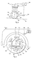
- Fig. 1 shows a circular wheel 100 where a first observation point 101 is located exactly at the wheel hub, a second observation point 102 is located at a distance r s from the hub and a third observation point 103 is located at the rim of the wheel so that the distance between it and the center point 101 is r, i.e. the same as the radius of the wheel.
- the second and third observation points 102 and 103 are placed along a single imaginary radial line.
- the wheel 100 is moving to the right in the horizontal direction at a speed v as well as rotating clockwise at an angular speed ⁇ .
- the horizontal and angular speeds as scalar quantities.
- the translational and rotational movements of the wheel are not linked to each other.
- the special case referred to above is the one where the wheel 100 is a part of a vehicle like a car or a train which runs on a road or a track.
- the speed of the car is 160 km/h and the ratio r s /r is equal to 3/4.
- Fig. 2 shows a plot of the momentary horizontal speeds of the observation points 101, 102, and 103 as functions of the angle ⁇ with curves 201, 202 and 203 respectively.
- the curves 202 and 203 exhibit sinusoidal oscillations around the mean value of 160 km/h.
- Fig. 4 shows the plots of the momentary horizontal speeds of the points 301 to 306 as functions of the angle ⁇ with curves 401 to 406 respectively.
- the translational speed of the wheel is v
- its angular speed is ⁇ (with no specific relationship to the translational speed)
- the rotation angle of a certain observation point in relation to the direction of the translational speed v is ⁇ t (where t means time).
- the range of rotational angles within which the horizontal speed of a certain observation point is smaller than the horizontal speed of all other observation points is the range when ⁇ t is larger than ( ⁇ - ⁇ )/2 but smaller than ( ⁇ + ⁇ )/2.
- Formula (4) can be used for system design: if for example the parameters v, ⁇ , r s and v limit are fixed, a simple manipulation of formula (4) gives the minimum number N of equidistant observation points. Similarly if the parameters v, ⁇ , N and v limit are fixed, formula (4) gives the minimum distance r s . Or if the parameters v, ⁇ , r s and N are fixed, formula (4) gives the achievable limiting speed v limit .
- FIG. 5 illustrates schematically an embodiment of the invention which is based on the above-given theoretical background.
- a wheel 500 is arranged to roll on an essentially horizontal surface 104.
- Six antennas 501 to 506 which are suitable for radio reception are mounted on the wheel at an equal radial distance from the center point of the wheel and at equal angular distances from each other.
- Each antenna is coupled to an RF switch 507 which is capable of selecting one antenna at a time for use.
- the RF switch 507 is further coupled to a radio receiver 508.
- a sensor 509 monitors the velocity and position of the wheel 500 and has a coupling to the RF switch 507 for giving control information.
- the arrangement of Fig. 5 operates as follows. As the wheel 500 rolls on the surface 104, there is always one antenna the horizontal velocity of which is smaller than the horizontal velocity of all other antennas.
- the "minimum velocity" antenna is always the one for which the radial line between it and the center point is at an absolute angle smaller than ⁇ /3 to the straight line connecting the center point and the point of the wheel which is against the surface 104.
- the sensor 509 is arranged to inform the RF switch 507 about the position of the wheel 500 so that at each time the RF switch 507 couples the "minimum velocity" antenna to the radio receiver 508.
- the radio receiver 508 receives a radio signal in which the maximum doppler shift corresponds to a translational speed of 60 km/h or less. It is clear from formula (4) that if the number of antennas or the radius at which they are installed in the wheel is increased, the car or railway carriage may travel even faster without increasing the momentary horizontal velocity of the antenna coupled to the radio receiver.
- Fig. 6 shows an exemplary wheel 600 on a vehicle.
- Six antennas 601 to 606 are mounted at a constant radial distance from the hub of the wheel and at equal angular displacements from each other. From each antenna there is a coaxial cable connection to an RF switch 607 which in turn has a coaxial cable connection to a first short distance wireless link transceiver 608.
- a second short distance wireless link transceiver 609 is mounted into the vehicle chassis so that a short distance wireless link may be established between the transceivers 608 and 609 (in a simpler embodiment there is a transmitter 608 in the wheel and a receiver 609 in the vehicle chassis so that the short distance wireless link is unidirectional).
- the second short distance wireless link transceiver 609 has a coaxial cable connection to a terminal arrangement 610 which is at least partly placed within the passenger cabin of the vehicle.
- the RF switch 607 and the first short distance wireless link transceiver 608 need some electrical power for operating.
- Fig. 6 there are two power generating units 611 and 612 fixed to the wheel 600 and having a cable connection to the short distance wireless link transceiver 608 and the RF switch respectively.
- Each of the power generating units 611 and 612 houses a piezoelectric voltage generator and a small rechargeable battery (not separately shown in Fig. 6).
- the piezoelectric voltage generators convert some of the mechanical energy associated with the movement of the wheel into electrical energy, part of which is provided to the short distance wireless link transceiver 608 and the RF switch while the rest is stored into the rechargeable batteries.
- the second short distance wireless link transceiver 609 as well as the terminal arrangement 610 are most advantageously coupled to the main electrical system of the vehicle in order to get the required electrical energy.
- odometer 613 The information about the position and movement of the wheel 600 which the RF switch 607 needs for selecting the correct antenna is provided by an odometer 613, where a small accelerometer and the associated integrators and other signal processing units (not separately shown in Fig. 6) monitor the state of movement of the wheel. Odometers of this kind are well known to the person skilled in the art, or equally well designed through the use of routine skills from the basis of existing knowledge of odometers.
- the short distance wireless link between the transceivers 608 and 609 is most advantageously a radio link, although also other forms of wireless links can be used. In some cases it may even be possible to use a wired link through certain sliding contact means at the hub of the wheel.
- Fig. 7 illustrates schematically an arrangement where there are six antennas 701a-701f in a first wheel, six antennas 702a-702f in a second wheel, six antennas 703a-703f in a third wheel and six antennas 704a-704f in a fourth wheel.
- Each group of siz antennas is coupled to an RF switch, of which RF switches 705, 706, 707 and 708 are shown. These are further coupled to a control block 709 and a central RF switch 710, which is coupled to a terminal arrangement 711.
- the reason for using a separate central switch 710 and a control block 709 is that the switches 705, 706, 707 and 708 are settable and the central switch is "rotatable", i.e. repeatedly settable at a high rate. Initially each of the switches 705, 706, 707 and 708 only selects one antenna into use at each wheel.
- the control block 709 monitors the signals obtained through each wheel and commands, if necessary, some of the switches 705, 706, 707 and 708 to select another antenna until a certain target state has been reached.
- the target state is such where the central switch 710 can cyclically switch through the four parallel input signals coming from the switches 705, 706, 707 and 708 so that at all times the selected input signal contains the minimum obtainable doppler shift. Fig.
- each wheel 801, 802, 803 and 804 houses an arrangement corresponding to that described in Fig. 6, and the short distance wireless link transceivers 805, 806, 807 and 808 couple the wheels to a central processing unit which houses the functionalities of the blocks 709, 710 and 711 of Fig. 7.
- FIG. 9 illustrates schematically an antenna wheel 900 with a multitude of mutually similar antennas attached to its outer rim; antennas 901 to 907 are shown.
- An RF switch 908 on the wheel selects always one of the antennas into use and couples it to a terminal arrangement 909 through a schematically shown coupling.
- a motor 910 is provided for rotating the antenna wheel 900 around its central axis. The rotating speed of the motor 910 is determined by a controller 911 which receives input information from the vehicle's speedometer.
- Fig. 9 operates so that when the controller 911 knows the translational speed of the vehicle, it sets the rotating speed of the motor 910 so that at the intersection of the rim of the wheel 900 and a radial line perpendicular to the velocity vector of the vehicle the rim moves with an instantaneous speed which is equal in absolute magnitude but opposite in direction to the vehicle speed.
- the accuracy in setting the rotating speed of the motor is not critical, since errors of several tens of km/h are tolerable.
- the RF switch 908 selects into use always that antenna which is closest to said "zero velocity" point.
- Fig. 10 illustrates a simplified version of the arrangement in Fig. 9.
- the antenna wheel 900 is rotated at a constant angular speed determined by a constant rotation controller 1001 regardless of the speed of the vehicle.
- the constant angular speed is selected so that when the vehicle does not move at all, at the intersection of the rim of the wheel 900 and a radial line perpendicular to the longitudinal axis of the vehicle the rim moves with an instantaneous speed which is e.g. about 60 km/h backwards.
- a compromise between the embodiments of Fig. 9 and 10 is such where the rotating speed of the motor 910 may be set to a selected constant value depending on the speed of the vehicle. At vehicle speeds under 140 km/h the rotating speed would be kept at a first constant value, and at higher vehicle speeds the rotating speed would be increased to a second, higher constant value.
- Fig. 11 illustrates a hybrid antenna arrangement where the arrangement of Fig. 10 has been complemented with an additional RF switch 1101 and a fixed antenna 1102 which is mounted e.g. on the vehicle chassis.
- the RF switch 1101 receives input information from the vehicle's speedometer. The idea is to use the fixed antenna 1102 at all times when the vehicle speed is under a certain limit, like 60 km/h.
- the antenna wheel 900 is rotated at a constant angular speed determined by the constant rotation controller 1001 regardless of the speed of the vehicle.
- the constant angular speed is selected so that when the vehicle does not move at all, at the intersection of the rim of the wheel 900 and a radial line perpendicular to the longitudinal axis of the vehicle the rim moves with an instantaneous speed which is e.g. about 120 km/h backwards.
- the RF switch 1101 selects the rotating antenna arrangement into use, which ensures low doppler shift at vehicle speeds up to 200 km/h with the above-given numerical values.
- the coupling between the moving body (the wheel) and the terminal is easier to implement than in those embodiments where the antennas are attached to the support wheels of a wheeled vehicle.
- the same short distance wireless link approach can be used also here, it is typically more advantageous to use a wired connection where sliding ring contacts, ring and brush contacts or other known arrangements are used to provide a galvanic coupling over rotational joints. Coupling a wired connection over a rotational joint is as such known to the person skilled in the art.
- Fig. 12 discloses a radically different approach where a multitude of antenna modules are attached to a conveyor belt 1200 supported on at least two circular wheels 1201 and 1202.
- the support wheels are positioned so that there is an essential straight segment of the conveyor belt that extends parallel to the longitudinal axis of the vehicle in which the antenna arrangement is to be used.
- a motor 910 and a rotation controller 911 are used to move the conveyor belt so that along said essential straight segment of the conveyor belt the antenna modules attached thereto move into a direction essentially opposite to the velocity vector of the vehicle.
- a certain antenna module 1203 is shown as a selected antenna module; from the position shown in Fig. 12 the antenna module 1203 moves for a certain duration of time towards the support wheel 1202 so that in relation to ground it remains essentially stationary, if the rotating speed of the motor 910 has been set correctly.
- the minimum number of antenna modules on the conveyor belt 1200 is three: if these are situated at equal distances (measured along the belt) from each other, there is always at least one antenna module moving linearly into a direction which is opposite to the velocity of the vehicle.
- each antenna module may have a short distance wireless link transceiver of its own, or one may use sliding contacts between the conveyor belt and the support wheels or a separate contact wheel or slider.
- the switching moment when the receiving antenna is changed causes an instantaneous phase shift in the signal that reaches the receiver.
- Some compensating action may be required to remove the effect of the phase shift.
- the exact moment of the phase shift is known to the receiver and antenna control circuitry, which helps in correctly timing and dimensioning the compensating action.
Landscapes
- Engineering & Computer Science (AREA)
- Computer Networks & Wireless Communication (AREA)
- Signal Processing (AREA)
- Remote Sensing (AREA)
- Variable-Direction Aerials And Aerial Arrays (AREA)
- Radar Systems Or Details Thereof (AREA)
- Transceivers (AREA)
- Ultra Sonic Daignosis Equipment (AREA)
- Details Of Aerials (AREA)
- Fittings On The Vehicle Exterior For Carrying Loads, And Devices For Holding Or Mounting Articles (AREA)
Applications Claiming Priority (2)
| Application Number | Priority Date | Filing Date | Title |
|---|---|---|---|
| FI992717 | 1999-12-17 | ||
| FI992717A FI19992717L (fi) | 1999-12-17 | 1999-12-17 | Järjestely doppler-siirtymän vaikutuksen vähentämiseksi radiovastaanotossa |
Publications (3)
| Publication Number | Publication Date |
|---|---|
| EP1109249A2 true EP1109249A2 (de) | 2001-06-20 |
| EP1109249A3 EP1109249A3 (de) | 2002-08-21 |
| EP1109249B1 EP1109249B1 (de) | 2003-12-03 |
Family
ID=8555766
Family Applications (1)
| Application Number | Title | Priority Date | Filing Date |
|---|---|---|---|
| EP00660231A Expired - Lifetime EP1109249B1 (de) | 1999-12-17 | 2000-12-15 | Anordnung zur Reduzierung des Effektes der Dopplerverschiebung beim Funkempfang |
Country Status (5)
| Country | Link |
|---|---|
| US (1) | US6400325B2 (de) |
| EP (1) | EP1109249B1 (de) |
| AT (1) | ATE255770T1 (de) |
| DE (1) | DE60006924T2 (de) |
| FI (1) | FI19992717L (de) |
Cited By (2)
| Publication number | Priority date | Publication date | Assignee | Title |
|---|---|---|---|---|
| EP1460780B1 (de) * | 2003-03-17 | 2005-10-26 | Sharp Kabushiki Kaisha | Antennenanordnung und damit ausgerüstetes elektronisches Gerät |
| EP2109917A4 (de) * | 2006-12-08 | 2010-04-21 | Lockheed Corp | Mobiles radar-array |
Families Citing this family (5)
| Publication number | Priority date | Publication date | Assignee | Title |
|---|---|---|---|---|
| JP2002009734A (ja) * | 2000-06-27 | 2002-01-11 | Denso Corp | Ofdm方式を用いた通信システム |
| JP3782330B2 (ja) * | 2001-09-14 | 2006-06-07 | 富士通株式会社 | Ofdm受信方法及びofdm受信装置 |
| US20030112804A1 (en) * | 2001-12-19 | 2003-06-19 | Jouni Kamarainen | Method, system and architecture for service broadcasting over orthogonal frequency division multiplexing using an internet protocol cellular network & session initiated protocol |
| JP2003243922A (ja) * | 2002-02-15 | 2003-08-29 | Toyota Central Res & Dev Lab Inc | アンテナ装置 |
| DE10317689A1 (de) * | 2003-04-17 | 2004-10-28 | Robert Bosch Gmbh | HF-Felgenantenne mit mehreren Patch-Antennen |
Family Cites Families (5)
| Publication number | Priority date | Publication date | Assignee | Title |
|---|---|---|---|---|
| US3503070A (en) * | 1969-04-01 | 1970-03-24 | Bell Telephone Labor Inc | Anti-doppler shift antenna for mobile radio |
| DE3346155A1 (de) | 1983-12-21 | 1985-07-04 | Licentia Patent-Verwaltungs-Gmbh, 6000 Frankfurt | Flugkoerper zur stoerung von bodengebundenen sende-empfangs-einrichtungen |
| EP0582364A1 (de) | 1992-08-05 | 1994-02-09 | International Business Machines Corporation | HF-Antenne für einen Hubschrauber |
| US5673049A (en) | 1996-01-26 | 1997-09-30 | Kitchen; William J. | Police radar jammer |
| US6204758B1 (en) * | 1999-07-23 | 2001-03-20 | Schrader-Bridgeport International, Inc. | System to automatically determine wheel position for automotive remote tire monitoring system |
-
1999
- 1999-12-17 FI FI992717A patent/FI19992717L/fi unknown
-
2000
- 2000-12-14 US US09/737,282 patent/US6400325B2/en not_active Expired - Fee Related
- 2000-12-15 DE DE60006924T patent/DE60006924T2/de not_active Expired - Fee Related
- 2000-12-15 AT AT00660231T patent/ATE255770T1/de not_active IP Right Cessation
- 2000-12-15 EP EP00660231A patent/EP1109249B1/de not_active Expired - Lifetime
Cited By (2)
| Publication number | Priority date | Publication date | Assignee | Title |
|---|---|---|---|---|
| EP1460780B1 (de) * | 2003-03-17 | 2005-10-26 | Sharp Kabushiki Kaisha | Antennenanordnung und damit ausgerüstetes elektronisches Gerät |
| EP2109917A4 (de) * | 2006-12-08 | 2010-04-21 | Lockheed Corp | Mobiles radar-array |
Also Published As
| Publication number | Publication date |
|---|---|
| FI19992717A7 (fi) | 2001-06-18 |
| DE60006924D1 (de) | 2004-01-15 |
| FI19992717L (fi) | 2001-06-18 |
| DE60006924T2 (de) | 2004-05-27 |
| EP1109249A3 (de) | 2002-08-21 |
| ATE255770T1 (de) | 2003-12-15 |
| US20010005182A1 (en) | 2001-06-28 |
| US6400325B2 (en) | 2002-06-04 |
| EP1109249B1 (de) | 2003-12-03 |
Similar Documents
| Publication | Publication Date | Title |
|---|---|---|
| US6397067B1 (en) | Roadside transmitter | |
| KR100828866B1 (ko) | 안테나 패턴을 제어하기 위한 시스템 및 방법 | |
| EP2959601B1 (de) | Verfahren und vorrichtung für fokussierte datenkommunikationen | |
| US6281839B1 (en) | Method and system for communicating electromagnetic signals | |
| EP2847887B1 (de) | Subsystem für dopplerverschiebungskorrektur bei einer kommunikationsvorrichtung | |
| ATE374470T1 (de) | Kommunikationssystem fahrzeug zu strassenrand, kommunikationsstation am strassenrand, und mobile bordstation | |
| EP1109249B1 (de) | Anordnung zur Reduzierung des Effektes der Dopplerverschiebung beim Funkempfang | |
| WO1999012230A9 (en) | Steerable antenna system | |
| WO2011045828A1 (ja) | 車載無線通信装置および車載無線通信システム | |
| US12316418B2 (en) | Transceiver, wireless communication system and wireless communication method | |
| KR20000076736A (ko) | 시임레스 양방향 도로 통신 시스템 및 그 방법 | |
| JP3749877B2 (ja) | 無線通信装置及び無線通信システム | |
| WO2005096520A1 (ja) | 移動受信装置 | |
| US3503070A (en) | Anti-doppler shift antenna for mobile radio | |
| JP2006157117A (ja) | 移動体通信システム | |
| CN113964476B (zh) | 一种动中通天线系统和载体 | |
| CA3127949C (en) | Method and apparatus for communications within a toroidal optical slip ring | |
| JP2009005037A (ja) | 無線通信装置、地上車上間無線通信システムおよび地上移動体間無線通信システム | |
| JP2001028576A (ja) | 車載受信装置 | |
| JP2000261358A (ja) | 衛星通信受信装置 | |
| JP4059762B2 (ja) | 車載用アンテナシステムの指向性制御装置 | |
| JP2017184031A (ja) | デジタル無線通信装置およびデジタル無線通信システム | |
| JP2005236799A (ja) | 無線装置及びその空中線方向調整方法 | |
| JPS63233620A (ja) | 移動通信方式 | |
| JPH0828678B2 (ja) | 複局同時送信方式 |
Legal Events
| Date | Code | Title | Description |
|---|---|---|---|
| PUAI | Public reference made under article 153(3) epc to a published international application that has entered the european phase |
Free format text: ORIGINAL CODE: 0009012 |
|
| AK | Designated contracting states |
Kind code of ref document: A2 Designated state(s): AT BE CH CY DE DK ES FI FR GB GR IE IT LI LU MC NL PT SE TR |
|
| AX | Request for extension of the european patent |
Free format text: AL;LT;LV;MK;RO;SI |
|
| RAP1 | Party data changed (applicant data changed or rights of an application transferred) |
Owner name: NOKIA CORPORATION |
|
| PUAL | Search report despatched |
Free format text: ORIGINAL CODE: 0009013 |
|
| AK | Designated contracting states |
Kind code of ref document: A3 Designated state(s): AT BE CH CY DE DK ES FI FR GB GR IE IT LI LU MC NL PT SE TR |
|
| AX | Request for extension of the european patent |
Free format text: AL;LT;LV;MK;RO;SI |
|
| 17P | Request for examination filed |
Effective date: 20030117 |
|
| 17Q | First examination report despatched |
Effective date: 20030226 |
|
| AKX | Designation fees paid |
Designated state(s): AT BE CH CY DE DK ES FI FR GB GR IE IT LI LU MC NL PT SE TR |
|
| GRAH | Despatch of communication of intention to grant a patent |
Free format text: ORIGINAL CODE: EPIDOS IGRA |
|
| GRAS | Grant fee paid |
Free format text: ORIGINAL CODE: EPIDOSNIGR3 |
|
| GRAA | (expected) grant |
Free format text: ORIGINAL CODE: 0009210 |
|
| AK | Designated contracting states |
Kind code of ref document: B1 Designated state(s): AT BE CH CY DE DK ES FI FR GB GR IE IT LI LU MC NL PT SE TR |
|
| PG25 | Lapsed in a contracting state [announced via postgrant information from national office to epo] |
Ref country code: IT Free format text: LAPSE BECAUSE OF FAILURE TO SUBMIT A TRANSLATION OF THE DESCRIPTION OR TO PAY THE FEE WITHIN THE PRESCRIBED TIME-LIMIT;WARNING: LAPSES OF ITALIAN PATENTS WITH EFFECTIVE DATE BEFORE 2007 MAY HAVE OCCURRED AT ANY TIME BEFORE 2007. THE CORRECT EFFECTIVE DATE MAY BE DIFFERENT FROM THE ONE RECORDED. Effective date: 20031203 Ref country code: AT Free format text: LAPSE BECAUSE OF FAILURE TO SUBMIT A TRANSLATION OF THE DESCRIPTION OR TO PAY THE FEE WITHIN THE PRESCRIBED TIME-LIMIT Effective date: 20031203 Ref country code: CH Free format text: LAPSE BECAUSE OF FAILURE TO SUBMIT A TRANSLATION OF THE DESCRIPTION OR TO PAY THE FEE WITHIN THE PRESCRIBED TIME-LIMIT Effective date: 20031203 Ref country code: FI Free format text: LAPSE BECAUSE OF FAILURE TO SUBMIT A TRANSLATION OF THE DESCRIPTION OR TO PAY THE FEE WITHIN THE PRESCRIBED TIME-LIMIT Effective date: 20031203 Ref country code: BE Free format text: LAPSE BECAUSE OF FAILURE TO SUBMIT A TRANSLATION OF THE DESCRIPTION OR TO PAY THE FEE WITHIN THE PRESCRIBED TIME-LIMIT Effective date: 20031203 Ref country code: NL Free format text: LAPSE BECAUSE OF FAILURE TO SUBMIT A TRANSLATION OF THE DESCRIPTION OR TO PAY THE FEE WITHIN THE PRESCRIBED TIME-LIMIT Effective date: 20031203 Ref country code: TR Free format text: LAPSE BECAUSE OF FAILURE TO SUBMIT A TRANSLATION OF THE DESCRIPTION OR TO PAY THE FEE WITHIN THE PRESCRIBED TIME-LIMIT Effective date: 20031203 Ref country code: LI Free format text: LAPSE BECAUSE OF FAILURE TO SUBMIT A TRANSLATION OF THE DESCRIPTION OR TO PAY THE FEE WITHIN THE PRESCRIBED TIME-LIMIT Effective date: 20031203 |
|
| REG | Reference to a national code |
Ref country code: GB Ref legal event code: FG4D |
|
| PG25 | Lapsed in a contracting state [announced via postgrant information from national office to epo] |
Ref country code: CY Free format text: LAPSE BECAUSE OF FAILURE TO SUBMIT A TRANSLATION OF THE DESCRIPTION OR TO PAY THE FEE WITHIN THE PRESCRIBED TIME-LIMIT Effective date: 20031215 Ref country code: LU Free format text: LAPSE BECAUSE OF NON-PAYMENT OF DUE FEES Effective date: 20031215 Ref country code: IE Free format text: LAPSE BECAUSE OF NON-PAYMENT OF DUE FEES Effective date: 20031215 |
|
| REG | Reference to a national code |
Ref country code: CH Ref legal event code: EP |
|
| PG25 | Lapsed in a contracting state [announced via postgrant information from national office to epo] |
Ref country code: MC Free format text: LAPSE BECAUSE OF NON-PAYMENT OF DUE FEES Effective date: 20031231 |
|
| REG | Reference to a national code |
Ref country code: IE Ref legal event code: FG4D |
|
| REF | Corresponds to: |
Ref document number: 60006924 Country of ref document: DE Date of ref document: 20040115 Kind code of ref document: P |
|
| PG25 | Lapsed in a contracting state [announced via postgrant information from national office to epo] |
Ref country code: SE Free format text: LAPSE BECAUSE OF FAILURE TO SUBMIT A TRANSLATION OF THE DESCRIPTION OR TO PAY THE FEE WITHIN THE PRESCRIBED TIME-LIMIT Effective date: 20040303 Ref country code: GR Free format text: LAPSE BECAUSE OF FAILURE TO SUBMIT A TRANSLATION OF THE DESCRIPTION OR TO PAY THE FEE WITHIN THE PRESCRIBED TIME-LIMIT Effective date: 20040303 Ref country code: DK Free format text: LAPSE BECAUSE OF FAILURE TO SUBMIT A TRANSLATION OF THE DESCRIPTION OR TO PAY THE FEE WITHIN THE PRESCRIBED TIME-LIMIT Effective date: 20040303 |
|
| PG25 | Lapsed in a contracting state [announced via postgrant information from national office to epo] |
Ref country code: ES Free format text: LAPSE BECAUSE OF FAILURE TO SUBMIT A TRANSLATION OF THE DESCRIPTION OR TO PAY THE FEE WITHIN THE PRESCRIBED TIME-LIMIT Effective date: 20040314 |
|
| NLV1 | Nl: lapsed or annulled due to failure to fulfill the requirements of art. 29p and 29m of the patents act | ||
| REG | Reference to a national code |
Ref country code: CH Ref legal event code: PL |
|
| ET | Fr: translation filed | ||
| REG | Reference to a national code |
Ref country code: IE Ref legal event code: MM4A |
|
| PLBE | No opposition filed within time limit |
Free format text: ORIGINAL CODE: 0009261 |
|
| STAA | Information on the status of an ep patent application or granted ep patent |
Free format text: STATUS: NO OPPOSITION FILED WITHIN TIME LIMIT |
|
| 26N | No opposition filed |
Effective date: 20040906 |
|
| PG25 | Lapsed in a contracting state [announced via postgrant information from national office to epo] |
Ref country code: PT Free format text: LAPSE BECAUSE OF NON-PAYMENT OF DUE FEES Effective date: 20040503 |
|
| PGFP | Annual fee paid to national office [announced via postgrant information from national office to epo] |
Ref country code: FR Payment date: 20081212 Year of fee payment: 9 |
|
| PGFP | Annual fee paid to national office [announced via postgrant information from national office to epo] |
Ref country code: DE Payment date: 20081211 Year of fee payment: 9 |
|
| PGFP | Annual fee paid to national office [announced via postgrant information from national office to epo] |
Ref country code: GB Payment date: 20081210 Year of fee payment: 9 |
|
| GBPC | Gb: european patent ceased through non-payment of renewal fee |
Effective date: 20091215 |
|
| REG | Reference to a national code |
Ref country code: FR Ref legal event code: ST Effective date: 20100831 |
|
| PG25 | Lapsed in a contracting state [announced via postgrant information from national office to epo] |
Ref country code: FR Free format text: LAPSE BECAUSE OF NON-PAYMENT OF DUE FEES Effective date: 20091231 |
|
| PG25 | Lapsed in a contracting state [announced via postgrant information from national office to epo] |
Ref country code: DE Free format text: LAPSE BECAUSE OF NON-PAYMENT OF DUE FEES Effective date: 20100701 |
|
| PG25 | Lapsed in a contracting state [announced via postgrant information from national office to epo] |
Ref country code: GB Free format text: LAPSE BECAUSE OF NON-PAYMENT OF DUE FEES Effective date: 20091215 |