EP1109307A2 - Regelung für eine bürstenlose Maschine - Google Patents
Regelung für eine bürstenlose Maschine Download PDFInfo
- Publication number
- EP1109307A2 EP1109307A2 EP00310689A EP00310689A EP1109307A2 EP 1109307 A2 EP1109307 A2 EP 1109307A2 EP 00310689 A EP00310689 A EP 00310689A EP 00310689 A EP00310689 A EP 00310689A EP 1109307 A2 EP1109307 A2 EP 1109307A2
- Authority
- EP
- European Patent Office
- Prior art keywords
- flux
- machine
- stator
- rotor
- phase winding
- Prior art date
- Legal status (The legal status is an assumption and is not a legal conclusion. Google has not performed a legal analysis and makes no representation as to the accuracy of the status listed.)
- Granted
Links
Images


Classifications
-
- H—ELECTRICITY
- H02—GENERATION; CONVERSION OR DISTRIBUTION OF ELECTRIC POWER
- H02P—CONTROL OR REGULATION OF ELECTRIC MOTORS, ELECTRIC GENERATORS OR DYNAMO-ELECTRIC CONVERTERS; CONTROLLING TRANSFORMERS, REACTORS OR CHOKE COILS
- H02P25/00—Arrangements or methods for the control of AC motors characterised by the kind of AC motor or by structural details
- H02P25/02—Arrangements or methods for the control of AC motors characterised by the kind of AC motor or by structural details characterised by the kind of motor
- H02P25/08—Reluctance motors
-
- H—ELECTRICITY
- H02—GENERATION; CONVERSION OR DISTRIBUTION OF ELECTRIC POWER
- H02P—CONTROL OR REGULATION OF ELECTRIC MOTORS, ELECTRIC GENERATORS OR DYNAMO-ELECTRIC CONVERTERS; CONTROLLING TRANSFORMERS, REACTORS OR CHOKE COILS
- H02P3/00—Arrangements for stopping or slowing electric motors, generators, or dynamo-electric converters
- H02P3/06—Arrangements for stopping or slowing electric motors, generators, or dynamo-electric converters for stopping or slowing an individual dynamo-electric motor or dynamo-electric converter
- H02P3/065—Arrangements for stopping or slowing electric motors, generators, or dynamo-electric converters for stopping or slowing an individual dynamo-electric motor or dynamo-electric converter for stopping or slowing a reluctance motor
Definitions
- This invention relates to the control of electronically switched, brushless machines, such as switched reluctance machines, permanent magnet machines and hybrids thereof.
- the typical switched reluctance machine for example, comprises a rotor, defining rotor poles, a stator defining stator poles, and a set of windings arranged in relation to the stator poles to define one or more phases.
- a reluctance machine energisation of one or more phase windings sets up a magnetic flux circuit including the associated stator poles, urging the rotor into a position of minimum reluctance. Timing the sequential energisation of the windings according to rotor position induces rotor movement.
- Switched reluctance machines are well known.
- switched reluctance machine As explained in the above paper, the method of torque production in a switched reluctance machine is quite different from that in conventional machines, e.g. induction or synchronous machines, which are operated by rotating waves of magneto-motive force (mmf) and in which the torque is produced by the interaction of a magnetic field with a current flowing in a conductor.
- Such machines are known as 'electromagnetic' machines and encompass, e.g., so-called brushless DC machines in which the current is in stator coils and the field is produced by permanent magnets on the rotor.
- switched reluctance machines are purely 'magnetic' machines, where the torque is produced solely by the magnetic field as the reluctance of the magnetic circuit changes.
- the rotor and the stator are made of unmagnetised, but magnetisable material, such as electrical sheet steel which is a typical 'soft' magnetic material. It follows that the methods of controlling the two types of machine are quite different, since the control is related to the method of torque production. In general, the control methods used for conventional sinusoidally fed conventional machines are quite inappropriate for switched reluctance machines.
- FIG. 1 shows a typical switched reluctance machine in cross section.
- the stator 10 has six stator poles 12, and the rotor 14 has four rotor poles 16.
- Each stator pole carries a coil 18.
- the coils on diametrically opposite poles are connected in series to provide three phase windings. Only one phase winding is shown, for clarity.
- the control of the switched reluctance machine can be achieved in a variety of ways.
- the machine could be controlled in an open-loop fashion, i.e. as commonly used for stepping motors. In this regime, the phase windings in the machine are sent pulses in turn and it is assumed that the rotor lines up with each pair of stator poles in turn, i.e.
- a typical switched reluctance drive is shown in Figure 2.
- the machine 36 corresponds to that shown in Figure 1.
- the three phase windings, A, B and C are switched onto a d.c. supply V by a set of power electronic switches 48.
- the moments at which the switches operate are determined by the controller 38, which may be implemented either in hardware or in the software of a microcontroller or digital signal processor.
- the firing signals are sent to the switches via a data bus 46. Closed loop current feedback is provided by sensing the phase currents by a current sensor 44 and feeding back a signal proportional to phase current.
- the control algorithms often include a proportional (P), proportional-plus-integral (P+I), time optimal, feedback linearised, proportional/integral/derivative (PID) function, or one of many others as is well understood in the art. It is also common for an outer control loop of position or speed to be provided by feeding back a rotor position signal from a position detector 40.
- P proportional
- P+I proportional-plus-integral
- PID proportional/integral/derivative
- a current demand i D on line 42 is provided to the controller and this regulates the current in the windings, according to the particular control scheme adopted, to produce the desired output from the machine.
- a current demand i D on line 42 is provided to the controller and this regulates the current in the windings, according to the particular control scheme adopted, to produce the desired output from the machine.
- the more fundamental control variable in a switched reluctance machine is the flux which is set up in the magnetic circuit in the machine when a phase winding is energised.
- the flux is directly responsible for the force which acts on the rotor to urge it to a position of minimum reluctance, i.e. to pull the rotor round, with respect to the energised stator poles.
- This invention uses closed-loop determination and control of flux to achieve much better performance from the machine than has hitherto been possible with closed-loop control of current.
- a brushless electrical machine comprising: a rotor; a stator; at least one phase winding arranged to establish flux in a magnetic circuit in the machine; and transducer means arranged in relation to the magnetic circuit to produce a flux signal indicative of the flux in a flux path associated with the at least one phase winding.
- the machine which can be run as a motor or a generator, derives the flux signal indicative of the flux itself from the magnetic circuit.
- the flux signal may be the output of a transducer arranged to measure directly the flux in the magnetic circuit.
- the transducer means may be arranged directly in the flux path. To avoid the transducer being an excessive contributor to the reluctance of the magnetic circuit, it may be arranged in the flux path but so that it only takes up a fraction of the area of the flux path.
- the transducer means can conveniently be arranged in a recess of a pole face of a stator pole or be deposited on a pole face.
- the transducer means can be any device known to produce an output that is indicative of the flux present.
- One example is a Hall-effect device that produces a voltage output that is directly proportional to the flux.
- the invention enables direct flux control of the machine which has been found to be more accurate and is more amenable to on-line adaptation than the current-based control previously used. It uses a real-time determination of flux, as opposed to a selection from a set of stored values. It is, thus, adaptable to different types of machine and is not dedicated to a specific machine.
- the invention also extends to a brushless electrical machine drive system
- a brushless electrical machine drive system comprising a brushless electrical machine having a rotor, a stator and at least one phase winding arranged to establish flux in a magnetic circuit in the machine; transducer means arranged in relation to the magnetic circuit to produce a flux signal indicative of the flux in a flux path associated with the at least one phase winding; switch means electrically connected with the at least one phase winding; and flux control means having an input signal representing the demanded output of the machine, which control means are responsive to the input signal and the flux signal to produce control signals for controlling the flux in the or each phase winding.
- the flux control means are responsive to the input signal and the flux signal to produce the control signals according to a proportional, proportional-plus-integral, proportional/integral/derivative, time optimal or feedback linearised control law.
- the flux control means further includes means for timing the control signals for actuating the excitation means.
- the invention also extends to a method of controlling a brushless electrical machine having a rotor, a stator and at least one phase winding, the method comprising: arranging transducer means in a magnetic circuit of the machine to produce a flux signal indicative of the flux in the at least one phase winding; producing an input signal representing the demanded output of the machine; controlling energisation of the at least one phase winding in response to the input signal and the flux signal.
- a first embodiment of a switched reluctance drive system includes a switched reluctance machine 36 having a laminated stator 10 and a laminated rotor 14, both made from soft magnetic material, e.g. electrical sheet steel, in relation to which is arranged a rotor position transducer (RPT) 40.
- a flux controller 50 produces firing signals for actuating power electronic switches 48 for controlling the energisation of the phase windings A, B and C associated with the stator 10.
- the schematically illustrated connection of only one phase winding is shown for the sake of clarity, but each phase is independently excitable by actuation of the switches.
- the excitation for the windings is provided by an amplifier of known type.
- the flux controller 50 is provided with three types of feedback signal: rotor position signals ⁇ from the RPT 40; phase current signals i from the current transducer 44; and flux signals ⁇ proportional to the measured flux in the phase winding. It will be appreciated that each phase winding will have associated with it a current transducer 44 for the current signals i. Only one is shown for the sake of clarity.
- the input 42' to the flux controller 50 is a signal representing the desired flux ⁇ D in the machine to produce a desired output. In operating the machine as a motor, the desired output is torque, speed or position. In operating the machine as a generator, the desired output is electrical power.
- the flux controller of Figure 3 is quite different in operation from the controller of Figure 2. Instead of a current demand controlling the output of the machine, the output is controlled directly by a flux demand: instead of current being the principal parameter fed back to correct the output, flux is now the principal feedback parameter. This is quite different from all known practicable controllers for switched reluctance machines.
- Figure 3 shows the flux controller receiving a flux feedback signal.
- this signal is produced by a Hall-effect device 60 which gives an electrical output that is directly proportional to the flux.
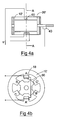
- Figure 4a shows an axial cross-section of a machine 36' suitable for use in the present invention. Viewed along the axis of the machine, at a point along the stator core 10' of the machine, a recess is formed in the pole face. The Hall-effect device 60 is mounted in the recess. A radial cross-section AA through the device is shown in Figure 4b. The device 60 could be mounted on the surface of the unmodified pole face of the stator pole, but space in the air gap between aligned rotor and stator poles is limited.
- the device is in the flux path. While the presence of the Hall-effect device 60 increases the reluctance at the position in which the rotor and stator poles are aligned, the effect of its presence on the reluctance of the flux path is negligible as a proportion of the overall flux path in the stack of laminations.
- the Hall-effect device 60 is directly in the flux path for that phase. As is well-known, the output of the Hall-effect device is a voltage signal directly proportional to the magnitude of the flux to which it is exposed. Therefore it acts as a flux transducer indicating the flux in the flux path for that phase, and the signal is fed back to the flux controller 50 as shown in Figure 3. For the sake of clarity, only the Hall-effect device for one phase is shown but it is to be understood that a similar device is provided for each phase or in each airgap of the machine.
- the Hall-effect device 60 is situated in the main flux path of phase A and gives a reliable measurement of the flux to which it is exposed. Its output can be scaled to account for the length of the stator core 10' and also for any fringing effects which occur at the ends of the core.
- the flux transducer 60 need not be positioned as shown in Figure 4 - it may be placed anywhere in relation to the magnetic circuit where it can give an output which reliably transduces the magnitude of the flux in the machine.
- the indication of the flux is preferably directly or inversely proportional to the transducer output. It need not be linearly proportional as long as the output can be scaled and is an unambiguous indication of flux without reference to other machine parameters or operating conditions.
- Figure 4 shows a Hall-effect device which is small relative to the dimensions of the pole 18.
- a thin layer of Hall-effect material is deposited on the pole face to form a larger transducer.
- a layer of magneto-resistive material is placed in the flux path to provide a signal proportional to flux in the magnetic circuit.
- any transducer which indicates the magnitude of flux and provides a suitable output signal can be used in this invention. Examples of other useful transducers are a Gaussmeter and a superconducting interference device (SQUID).
- the flux feedback signal ⁇ is compared with the demanded flux 42' to produce an error signal.
- the flux controller can follow any one of a range of control laws, such as proportional, proportional-plus-integral, proportional/integral/derivative, time optimal, feedback linearised.
- the machine 36' also has a conventional RPT 40, whose output ⁇ provides timing information to the flux controller 50 in conventional manner.
- Alternative embodiments use so-called sensorless position detection systems which estimate position from other parameters of the machine, as is known in the art.
- the flux controller 50 may also receive a current signal i from the current transducer 44, though this is not used in the manner of a conventional current controller: rather, it is used simply to provide overall monitoring of current to ensure that it stays within a predetermined safe level.
- the flux controller 50 produces firing signals for the switching devices 48 that control energisation of the phase windings.
- the invention provides a flux control technique for electronically switched brushless machines of various types. It produces a real-time signal of the flux in the magnetic circuit of the machine to which a reference value of flux can be compared to control the machine output. It will be apparent to the skilled person that various modifications and changes can be made to the specifically disclosed embodiments without departing from the invention. The invention is to be limited only by the spirit and scope of the following claims.
Landscapes
- Engineering & Computer Science (AREA)
- Power Engineering (AREA)
- Control Of Electric Motors In General (AREA)
- Control Of Motors That Do Not Use Commutators (AREA)
Applications Claiming Priority (2)
| Application Number | Priority Date | Filing Date | Title |
|---|---|---|---|
| GB9929995 | 1999-12-17 | ||
| GBGB9929995.0A GB9929995D0 (en) | 1999-12-17 | 1999-12-17 | Brushless machine control |
Publications (3)
| Publication Number | Publication Date |
|---|---|
| EP1109307A2 true EP1109307A2 (de) | 2001-06-20 |
| EP1109307A3 EP1109307A3 (de) | 2003-04-16 |
| EP1109307B1 EP1109307B1 (de) | 2006-07-26 |
Family
ID=10866609
Family Applications (1)
| Application Number | Title | Priority Date | Filing Date |
|---|---|---|---|
| EP00310689A Expired - Lifetime EP1109307B1 (de) | 1999-12-17 | 2000-12-01 | Regelung für eine bürstenlose Maschine |
Country Status (6)
| Country | Link |
|---|---|
| US (1) | US6441580B2 (de) |
| EP (1) | EP1109307B1 (de) |
| JP (1) | JP2001197776A (de) |
| KR (1) | KR100665075B1 (de) |
| DE (1) | DE60029548T2 (de) |
| GB (1) | GB9929995D0 (de) |
Cited By (1)
| Publication number | Priority date | Publication date | Assignee | Title |
|---|---|---|---|---|
| EP1988627A2 (de) | 2007-05-04 | 2008-11-05 | Switched Reluctance Drives Limited | Steuerung einer bürstenlosen elektrischen Maschine |
Families Citing this family (25)
| Publication number | Priority date | Publication date | Assignee | Title |
|---|---|---|---|---|
| KR100442122B1 (ko) * | 2001-07-31 | 2004-07-30 | 한국전기연구원 | 영구 자석을 이용한 브러시리스 발전기 |
| US7250734B1 (en) | 2003-05-27 | 2007-07-31 | Synchrony, Inc. | High performance switched reluctance machine |
| GB0415166D0 (en) * | 2004-07-06 | 2004-08-11 | Switched Reluctance Drives Ltd | Rotor position detection in an electrical machine |
| US7342379B2 (en) | 2005-06-24 | 2008-03-11 | Emerson Electric Co. | Sensorless control systems and methods for permanent magnet rotating machines |
| US7208895B2 (en) | 2005-06-24 | 2007-04-24 | Emerson Electric Co. | Control systems and methods for permanent magnet rotating machines |
| GB0625637D0 (en) * | 2006-12-21 | 2007-01-31 | Switched Reluctance Drives Ltd | Operation of an electrical drive system |
| DE102007057990B3 (de) * | 2007-12-03 | 2009-04-16 | Knorr-Bremse Systeme für Nutzfahrzeuge GmbH | Verfahren und Schaltungsanordnung zur Überwachung von durch elektrische Impulse angesteuerten Geräten |
| KR20110014590A (ko) | 2008-04-17 | 2011-02-11 | 신크로니, 아이엔씨. | 저-손실 금속 회전자를 구비한 고속 영구자석 모터 및 발전기 |
| CA2721818A1 (en) | 2008-04-18 | 2009-11-19 | Synchrony, Inc. | Magnetic thrust bearing with integrated electronics |
| US9583991B2 (en) | 2009-06-24 | 2017-02-28 | Synchrony, Inc. | Systems, devices, and/or methods for managing magnetic bearings |
| US8493014B2 (en) * | 2009-08-10 | 2013-07-23 | Emerson Climate Technologies, Inc. | Controller and method for estimating, managing, and diagnosing motor parameters |
| US8358098B2 (en) * | 2009-08-10 | 2013-01-22 | Emerson Climate Technologies, Inc. | System and method for power factor correction |
| US8264860B2 (en) * | 2009-08-10 | 2012-09-11 | Emerson Climate Technologies, Inc. | System and method for power factor correction frequency tracking and reference generation |
| US8476873B2 (en) * | 2009-08-10 | 2013-07-02 | Emerson Climate Technologies, Inc. | System and method for current balancing |
| US8344706B2 (en) * | 2009-08-10 | 2013-01-01 | Emerson Climate Technologies, Inc. | System and method for rejecting DC current in power factor correction systems |
| US8698433B2 (en) | 2009-08-10 | 2014-04-15 | Emerson Climate Technologies, Inc. | Controller and method for minimizing phase advance current |
| US8508166B2 (en) | 2009-08-10 | 2013-08-13 | Emerson Climate Technologies, Inc. | Power factor correction with variable bus voltage |
| US8406021B2 (en) * | 2009-08-10 | 2013-03-26 | Emerson Climate Technologies, Inc. | System and method for reducing line current distortion |
| US8264192B2 (en) | 2009-08-10 | 2012-09-11 | Emerson Climate Technologies, Inc. | Controller and method for transitioning between control angles |
| US8987959B2 (en) | 2010-06-23 | 2015-03-24 | Dresser-Rand Company | Split magnetic thrust bearing |
| US9634593B2 (en) | 2012-04-26 | 2017-04-25 | Emerson Climate Technologies, Inc. | System and method for permanent magnet motor control |
| WO2014026124A1 (en) | 2012-08-10 | 2014-02-13 | Emerson Climate Technologies, Inc. | Motor drive control using pulse-width modulation pulse skipping |
| JP6303947B2 (ja) * | 2014-09-17 | 2018-04-04 | 株式会社デンソー | リラクタンス同期モータの駆動制御方法及びリラクタンス同期モータの駆動制御装置 |
| JP6643702B2 (ja) * | 2015-11-10 | 2020-02-12 | シンフォニアテクノロジー株式会社 | ロータ位置検出装置及びモータ制御装置 |
| US10641919B2 (en) * | 2016-12-14 | 2020-05-05 | Rock Visualization Technology, Llc | Passive cased well image logging |
Family Cites Families (15)
| Publication number | Priority date | Publication date | Assignee | Title |
|---|---|---|---|---|
| US4107591A (en) * | 1977-04-14 | 1978-08-15 | The Singer Company | Hall generator position sensing device |
| US4571479A (en) * | 1983-03-14 | 1986-02-18 | Mitsubishi Denki Kabushiki Kaisha | Welding machine with automatic seam tracking |
| US4715523A (en) * | 1984-11-12 | 1987-12-29 | Lebedev Vladimir K | Electromagnetic power drive for a friction welding machine |
| JPH0824435B2 (ja) * | 1985-03-07 | 1996-03-06 | 日本ビクター株式会社 | 直流ブラシレスモ−タ |
| US4896089A (en) * | 1989-01-31 | 1990-01-23 | General Electric Company | Fault management system for a switched reluctance motor |
| EP0505660B1 (de) * | 1991-03-27 | 1996-08-14 | COMELZ S.p.A. | Steuerungseinheit für einen elektrischen Antriebsmotor einer industriellen Verarbeitungsmaschine |
| GB9211685D0 (en) * | 1992-06-03 | 1992-07-15 | Switched Reluctance Drives Ltd | Sensorless rotor position measurement |
| US5696430A (en) | 1993-02-22 | 1997-12-09 | General Electric Company | Circuit, motor, and method generating a signal representing back EMF in an energized motor winding |
| GB9524022D0 (en) * | 1995-11-23 | 1996-01-24 | Barnes N M | Method of operating an electronic circuit |
| FI106231B (fi) * | 1996-02-13 | 2000-12-15 | Abb Industry Oy | Invertterijärjestely |
| JPH09326159A (ja) * | 1996-06-04 | 1997-12-16 | Alps Electric Co Ltd | インデックス信号形成回路 |
| US5841262A (en) * | 1997-03-25 | 1998-11-24 | Emerson Electric Co. | Low-cost universal drive for use with switched reluctance machines |
| FR2769422B1 (fr) * | 1997-10-07 | 1999-12-24 | Valeo Equip Electr Moteur | Machine electrique a commutation de flux, et notamment alternateur de vehicule automobile |
| US6091215A (en) | 1998-06-02 | 2000-07-18 | Switched Reluctance Drives Limited | Trajectory controller |
| US6509711B1 (en) * | 2000-04-26 | 2003-01-21 | Ford Global Technologies, Inc. | Digital rotor flux observer |
-
1999
- 1999-12-17 GB GBGB9929995.0A patent/GB9929995D0/en not_active Ceased
-
2000
- 2000-12-01 EP EP00310689A patent/EP1109307B1/de not_active Expired - Lifetime
- 2000-12-01 DE DE60029548T patent/DE60029548T2/de not_active Expired - Lifetime
- 2000-12-13 JP JP2000379467A patent/JP2001197776A/ja active Pending
- 2000-12-15 US US09/738,468 patent/US6441580B2/en not_active Expired - Lifetime
- 2000-12-16 KR KR1020000077481A patent/KR100665075B1/ko not_active Expired - Fee Related
Cited By (3)
| Publication number | Priority date | Publication date | Assignee | Title |
|---|---|---|---|---|
| EP1988627A2 (de) | 2007-05-04 | 2008-11-05 | Switched Reluctance Drives Limited | Steuerung einer bürstenlosen elektrischen Maschine |
| US7880415B2 (en) | 2007-05-04 | 2011-02-01 | Switched Reluctance Drives Limited | Control of a brushless electrical machine |
| KR101537780B1 (ko) * | 2007-05-04 | 2015-07-17 | 니덱 에스알 드라이브즈 리미티드 | 브러쉬리스 전기 기기의 제어 |
Also Published As
| Publication number | Publication date |
|---|---|
| KR100665075B1 (ko) | 2007-01-09 |
| GB9929995D0 (en) | 2000-02-09 |
| DE60029548D1 (de) | 2006-09-07 |
| US20010004196A1 (en) | 2001-06-21 |
| US6441580B2 (en) | 2002-08-27 |
| KR20010062525A (ko) | 2001-07-07 |
| JP2001197776A (ja) | 2001-07-19 |
| EP1109307B1 (de) | 2006-07-26 |
| DE60029548T2 (de) | 2007-07-26 |
| EP1109307A3 (de) | 2003-04-16 |
Similar Documents
| Publication | Publication Date | Title |
|---|---|---|
| US6441580B2 (en) | Brushless machine control | |
| US5140243A (en) | Discrete position estimator for a switched reluctance machine using a flux-current map comparator | |
| US5107195A (en) | Rotor position estimator for a switched reluctance machine using a lumped parameter flux/current model | |
| US5097190A (en) | Rotor position estimator for a switched reluctance machine | |
| US4961038A (en) | Torque estimator for switched reluctance machines | |
| US5525886A (en) | Low speed position estimator for switched reluctance machine using flux/current model | |
| US6650082B1 (en) | Fast rotor position detection apparatus and method for disk drive motor at standstill | |
| US5747962A (en) | Method and apparatus for increasing the starting torque of a two-phase switched reluctance motor | |
| EP0532350B1 (de) | Lockdetektor für den Positions-Beobachter einer geschalteten Reluktanzmaschine | |
| US5990643A (en) | Sensorless commutation position detection for brushless D.C. motors | |
| US6150778A (en) | Sensorless rotor position detection for switched reluctance machines having irregular poles | |
| JPS6240085A (ja) | ブラシレスモ−タ | |
| Panada et al. | Analysis of the waveform-detection technique for indirect roto-position sensing of switched reluctance motor drives | |
| JPH02228238A (ja) | 磁束集中形磁石を有する同期電動機 | |
| KR100745007B1 (ko) | 브러시리스 머신 제어 장치, 시스템 및 방법 | |
| US6184636B1 (en) | Motor control | |
| HK1051404A1 (zh) | 測定電動馬達負載角度的裝置 | |
| US20040108826A1 (en) | Method for characterizing a rotating electromagnetic machine | |
| Lee et al. | Sensorless commutation techniques for brushless permanent-magnet and reluctance motor drives | |
| WO2003084046A1 (en) | A control device for an electric motor, in particular a single-phase brushless synchronous motor with permanent magnets | |
| KR19990024344A (ko) | 가변릴럭턴스모터의 비선형 전류추종 제어방법과 장치 | |
| Arafa et al. | Surface-Mounted PMBM Sensorless Control Based On EMF Extraction And Extended Kalman Estimator | |
| JPH02123979A (ja) | 可変リラクタンス型acサーボモータの起動方法と装置 | |
| Gieras et al. | Investigation into an electronically-commutated dc motor with NdFe permanent magnets |
Legal Events
| Date | Code | Title | Description |
|---|---|---|---|
| PUAI | Public reference made under article 153(3) epc to a published international application that has entered the european phase |
Free format text: ORIGINAL CODE: 0009012 |
|
| AK | Designated contracting states |
Kind code of ref document: A2 Designated state(s): AT BE CH CY DE DK ES FI FR GB GR IE IT LI LU MC NL PT SE TR |
|
| AX | Request for extension of the european patent |
Free format text: AL;LT;LV;MK;RO;SI |
|
| PUAL | Search report despatched |
Free format text: ORIGINAL CODE: 0009013 |
|
| AK | Designated contracting states |
Designated state(s): AT BE CH CY DE DK ES FI FR GB GR IE IT LI LU MC NL PT SE TR |
|
| AX | Request for extension of the european patent |
Extension state: AL LT LV MK RO SI |
|
| 17P | Request for examination filed |
Effective date: 20031014 |
|
| AKX | Designation fees paid |
Designated state(s): DE FR GB IT |
|
| 17Q | First examination report despatched |
Effective date: 20040816 |
|
| GRAP | Despatch of communication of intention to grant a patent |
Free format text: ORIGINAL CODE: EPIDOSNIGR1 |
|
| RIC1 | Information provided on ipc code assigned before grant |
Ipc: H02P 25/08 20060101AFI20060112BHEP |
|
| GRAS | Grant fee paid |
Free format text: ORIGINAL CODE: EPIDOSNIGR3 |
|
| GRAA | (expected) grant |
Free format text: ORIGINAL CODE: 0009210 |
|
| AK | Designated contracting states |
Kind code of ref document: B1 Designated state(s): DE FR GB IT |
|
| REG | Reference to a national code |
Ref country code: GB Ref legal event code: FG4D |
|
| REF | Corresponds to: |
Ref document number: 60029548 Country of ref document: DE Date of ref document: 20060907 Kind code of ref document: P |
|
| ET | Fr: translation filed | ||
| PLBE | No opposition filed within time limit |
Free format text: ORIGINAL CODE: 0009261 |
|
| STAA | Information on the status of an ep patent application or granted ep patent |
Free format text: STATUS: NO OPPOSITION FILED WITHIN TIME LIMIT |
|
| 26N | No opposition filed |
Effective date: 20070427 |
|
| REG | Reference to a national code |
Ref country code: FR Ref legal event code: CD |
|
| REG | Reference to a national code |
Ref country code: DE Ref legal event code: R082 Ref document number: 60029548 Country of ref document: DE Representative=s name: UEXKUELL & STOLBERG, DE |
|
| REG | Reference to a national code |
Ref country code: DE Ref legal event code: R081 Ref document number: 60029548 Country of ref document: DE Owner name: NIDEC SR DRIVES LTD., HARROGATE, GB Free format text: FORMER OWNER: SWITCHED RELUCTANCE DRIVES LTD., HARROGATE, NORTH YORKSHIRE, GB Effective date: 20121217 Ref country code: DE Ref legal event code: R082 Ref document number: 60029548 Country of ref document: DE Representative=s name: UEXKUELL & STOLBERG PARTNERSCHAFT VON PATENT- , DE Effective date: 20121217 Ref country code: DE Ref legal event code: R081 Ref document number: 60029548 Country of ref document: DE Owner name: NIDEC SR DRIVES LTD., GB Free format text: FORMER OWNER: SWITCHED RELUCTANCE DRIVES LTD., HARROGATE, GB Effective date: 20121217 Ref country code: DE Ref legal event code: R082 Ref document number: 60029548 Country of ref document: DE Representative=s name: UEXKUELL & STOLBERG, DE Effective date: 20121217 |
|
| PGFP | Annual fee paid to national office [announced via postgrant information from national office to epo] |
Ref country code: IT Payment date: 20141223 Year of fee payment: 15 Ref country code: DE Payment date: 20150107 Year of fee payment: 15 |
|
| PGFP | Annual fee paid to national office [announced via postgrant information from national office to epo] |
Ref country code: FR Payment date: 20141217 Year of fee payment: 15 |
|
| REG | Reference to a national code |
Ref country code: DE Ref legal event code: R119 Ref document number: 60029548 Country of ref document: DE |
|
| REG | Reference to a national code |
Ref country code: FR Ref legal event code: ST Effective date: 20160831 |
|
| PG25 | Lapsed in a contracting state [announced via postgrant information from national office to epo] |
Ref country code: DE Free format text: LAPSE BECAUSE OF NON-PAYMENT OF DUE FEES Effective date: 20160701 |
|
| PG25 | Lapsed in a contracting state [announced via postgrant information from national office to epo] |
Ref country code: FR Free format text: LAPSE BECAUSE OF NON-PAYMENT OF DUE FEES Effective date: 20151231 |
|
| PG25 | Lapsed in a contracting state [announced via postgrant information from national office to epo] |
Ref country code: IT Free format text: LAPSE BECAUSE OF NON-PAYMENT OF DUE FEES Effective date: 20151201 |
|
| PGFP | Annual fee paid to national office [announced via postgrant information from national office to epo] |
Ref country code: GB Payment date: 20171123 Year of fee payment: 18 |
|
| GBPC | Gb: european patent ceased through non-payment of renewal fee |
Effective date: 20181201 |
|
| PG25 | Lapsed in a contracting state [announced via postgrant information from national office to epo] |
Ref country code: GB Free format text: LAPSE BECAUSE OF NON-PAYMENT OF DUE FEES Effective date: 20181201 |