EP1109308B1 - Commande d'un machine à reluctance commutée - Google Patents
Commande d'un machine à reluctance commutée Download PDFInfo
- Publication number
- EP1109308B1 EP1109308B1 EP00310807A EP00310807A EP1109308B1 EP 1109308 B1 EP1109308 B1 EP 1109308B1 EP 00310807 A EP00310807 A EP 00310807A EP 00310807 A EP00310807 A EP 00310807A EP 1109308 B1 EP1109308 B1 EP 1109308B1
- Authority
- EP
- European Patent Office
- Prior art keywords
- flux
- current
- phase
- model
- machine
- Prior art date
- Legal status (The legal status is an assumption and is not a legal conclusion. Google has not performed a legal analysis and makes no representation as to the accuracy of the status listed.)
- Expired - Lifetime
Links
- 230000004907 flux Effects 0.000 claims description 164
- 238000004804 winding Methods 0.000 claims description 59
- 238000000034 method Methods 0.000 claims description 17
- 230000004044 response Effects 0.000 claims description 6
- 230000002238 attenuated effect Effects 0.000 claims 1
- 230000006870 function Effects 0.000 description 22
- 230000000694 effects Effects 0.000 description 14
- 239000011159 matrix material Substances 0.000 description 14
- 238000005259 measurement Methods 0.000 description 11
- 230000001419 dependent effect Effects 0.000 description 7
- 238000010586 diagram Methods 0.000 description 7
- 230000010354 integration Effects 0.000 description 7
- 241000283891 Kobus Species 0.000 description 6
- 230000003044 adaptive effect Effects 0.000 description 6
- 230000014509 gene expression Effects 0.000 description 6
- 238000004364 calculation method Methods 0.000 description 4
- 230000005284 excitation Effects 0.000 description 4
- 238000001914 filtration Methods 0.000 description 4
- 238000010304 firing Methods 0.000 description 4
- 238000004519 manufacturing process Methods 0.000 description 4
- 230000007246 mechanism Effects 0.000 description 4
- NCGICGYLBXGBGN-UHFFFAOYSA-N 3-morpholin-4-yl-1-oxa-3-azonia-2-azanidacyclopent-3-en-5-imine;hydrochloride Chemical compound Cl.[N-]1OC(=N)C=[N+]1N1CCOCC1 NCGICGYLBXGBGN-UHFFFAOYSA-N 0.000 description 3
- 230000006978 adaptation Effects 0.000 description 3
- 230000008859 change Effects 0.000 description 3
- 238000002955 isolation Methods 0.000 description 3
- XEEYBQQBJWHFJM-UHFFFAOYSA-N Iron Chemical compound [Fe] XEEYBQQBJWHFJM-UHFFFAOYSA-N 0.000 description 2
- 230000008901 benefit Effects 0.000 description 2
- 238000004422 calculation algorithm Methods 0.000 description 2
- 230000007423 decrease Effects 0.000 description 2
- 230000001934 delay Effects 0.000 description 2
- 238000001514 detection method Methods 0.000 description 2
- 230000003993 interaction Effects 0.000 description 2
- 239000000463 material Substances 0.000 description 2
- 238000012544 monitoring process Methods 0.000 description 2
- 238000000819 phase cycle Methods 0.000 description 2
- 238000005295 random walk Methods 0.000 description 2
- 230000001360 synchronised effect Effects 0.000 description 2
- 239000013598 vector Substances 0.000 description 2
- 229910000831 Steel Inorganic materials 0.000 description 1
- 230000002159 abnormal effect Effects 0.000 description 1
- 230000009471 action Effects 0.000 description 1
- 238000013459 approach Methods 0.000 description 1
- 230000009286 beneficial effect Effects 0.000 description 1
- 239000004020 conductor Substances 0.000 description 1
- 230000008878 coupling Effects 0.000 description 1
- 238000010168 coupling process Methods 0.000 description 1
- 238000005859 coupling reaction Methods 0.000 description 1
- 230000003247 decreasing effect Effects 0.000 description 1
- 238000009795 derivation Methods 0.000 description 1
- 238000013461 design Methods 0.000 description 1
- 230000006698 induction Effects 0.000 description 1
- 229910052742 iron Inorganic materials 0.000 description 1
- 238000003475 lamination Methods 0.000 description 1
- 238000012886 linear function Methods 0.000 description 1
- 230000007774 longterm Effects 0.000 description 1
- 239000000203 mixture Substances 0.000 description 1
- 238000012986 modification Methods 0.000 description 1
- 230000004048 modification Effects 0.000 description 1
- 230000001575 pathological effect Effects 0.000 description 1
- 230000008569 process Effects 0.000 description 1
- 239000010959 steel Substances 0.000 description 1
- 238000013519 translation Methods 0.000 description 1
- 230000014616 translation Effects 0.000 description 1
Images



Classifications
-
- H—ELECTRICITY
- H02—GENERATION; CONVERSION OR DISTRIBUTION OF ELECTRIC POWER
- H02P—CONTROL OR REGULATION OF ELECTRIC MOTORS, ELECTRIC GENERATORS OR DYNAMO-ELECTRIC CONVERTERS; CONTROLLING TRANSFORMERS, REACTORS OR CHOKE COILS
- H02P25/00—Arrangements or methods for the control of AC motors characterised by the kind of AC motor or by structural details
- H02P25/02—Arrangements or methods for the control of AC motors characterised by the kind of AC motor or by structural details characterised by the kind of motor
- H02P25/08—Reluctance motors
Definitions
- This invention relates to the control of electronically switched, brushless machines, such as switched reluctance machines, permanent magnet machines and hybrids thereof.
- the typical switched reluctance machine for example, comprises a rotor, defining rotor poles, a stator defining stator poles, and a set of windings arranged in relation to the stator poles to define one or more phases.
- a reluctance machine energisation of one or more phase windings sets up a magnetic flux in the associated stator poles, urging the rotor into a position of minimum reluctance. Timing the sequential energisation of the windings according to rotor position induces rotor movement.
- Switched reluctance machines are well known.
- the method of torque production in a switched reluctance machine is quite different from that in conventional machines, e.g. induction or synchronous machines, which are operated by rotating waves of magneto-motive force (mmf) and in which the torque is produced by the interaction of a magnetic field with a current flowing in a conductor.
- Such machines are known as 'electromagnetic' machines and encompass, e.g., so-called brushless DC machines in which the current is in stator coils and the field is produced by permanent magnets on the rotor.
- switched reluctance machines are purely 'magnetic' machines, where the torque is produced solely by the magnetic field as the reluctance of the magnetic circuit changes. It follows that the methods of controlling the two types of machine are quite different, since the control is related to the method of torque production. In general, the control methods used for conventional, sinusoidally fed machines are quite inappropriate for switched reluctance machines.
- FIG. 1 shows a typical switched reluctance machine in cross section.
- the stator 10 has six stator poles 12, and the rotor 14 has four rotor poles 16.
- Each stator pole carries a coil 18.
- the coils on diametrically opposite poles are connected in series to provide three phase windings. Only one phase winding is shown, for clarity.
- the control of the switched reluctance machine can be achieved in a variety of ways.
- the machine could be controlled in an open-loop fashion, i.e. as commonly used for stepping motors. In this regime, the phase windings in the machine are sent pulses in turn and it is assumed that the rotor lines up with each pair of stator poles in turn, i.e.
- a typical switched reluctance drive is shown in Figure 2.
- the machine 36 corresponds to that shown in Figure 1.
- the three phase windings, A, B and C are switched onto a d.c. supply V by a set of power electronic switches 48.
- the moments at which the switches operate are determined by the controller 38, which may be implemented either in hardware or in the software of a microcontroller or digital signal processor.
- the firing signals are sent to the switches via a data bus 46. Closed loop current feedback is provided by sensing the phase currents by one or more current sensors 44 and feeding back signals proportional to phase current.
- the control algorithms often include a proportional (P), proportional-plus-integral (P+I), time optimal, feedback linearised, proportional/integral/derivative (PID) function, or one of many others as is well understood in the art. It is also common for an outer control loop of position or speed to be provided by feeding back a rotor position signal from a position detector 40.
- P proportional
- P+I proportional-plus-integral
- PID proportional/integral/derivative
- a current demand i D on line 42 is provided to the controller and this regulates the current in the windings, according to the particular control scheme adopted, to produce the desired output from the machine.
- a current demand i D on line 42 is provided to the controller and this regulates the current in the windings, according to the particular control scheme adopted, to produce the desired output from the machine.
- the more fundamental control variable in a switched reluctance machine is the flux which is set up in the magnetic circuit in the machine when a phase winding is energised.
- the flux is directly responsible for the force which acts on the rotor to urge it to a position of minimum reluctance, i.e. to pull the rotor round, with respect to the energised stator poles.
- This invention uses closed-loop real-time determination and control of flux to achieve much better performance from the machine than has hitherto been possible with closed-loop control of current.
- EP-A-0573198 discloses a system and method for sensorless rotor position measurement which uses sampled measurements of current and flux, compares these measurements with stored values and calculates an error value in order to predict the instant the rotor will reach the next reference position. It has been recognised by the inventor that the machine operating characteristic that is relatively easily determined, and that relates directly to the flux, is the voltage across the phase winding.
- the machine which can be run as a motor or a generator, derives the feedback signal indicative of the flux from the flux causing voltage.
- the flux causing voltage is estimated by a state observer arrangement.
- the current model is not sensitive to phase resistance, so the current model can be usefully arranged to dominate at "low speed" when little voltage is necessary to generate the required flux linkage. If the system is adaptive, the phase resistance can be more easily estimated at low speed while the observer is relying on the current model. At high speed the current model will be less accurate due to angle measurement errors being magnified as the speed increases. More applied phase voltage is required to generate the necessary flux linkage over the shorter phase cycle time.
- the voltage model is not sensitive to angle measurement error and is less sensitive to phase resistance at high speed.
- the voltage model (the integral with respect to time of the difference between the voltage applied to a phase and the voltage drop across that phase resistance) will also model complex effects like mutual inductance between phases in a simple manner. The total phase flux linkage is derived no matter which phase mmf is responsible.
- the invention enables direct flux control of the machine which has been found to be more accurate and is more amenable to on-line adaptation than the current-based control previously used. It uses a real-time determination of flux.
- the flux controller further includes means for timing the control signals for actuating the excitation means.
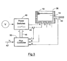
- a first embodiment of a switched reluctance drive system includes a switched reluctance machine 36 having a laminated stator 10 and a laminated rotor 14 in relation to which is arranged a rotor position transducer (RPT) 40.
- a flux controller 50 produces firing signals for actuating power electronic switches 48 for controlling the energisation of the phase windings A, B and C associated with the stator 10.
- the schematically illustrated connection of only one phase winding is shown for the sake of clarity, but each phase is independently excitable by actuation of the switches.
- the excitation for the windings is provided by an amplifier of known type.
- each phase winding will have associated with it a current transducer 44. Only one is shown for the sake of clarity.
- the input 42' to the flux controller 50 is a signal representing the desired flux ⁇ D in the machine to produce a desired output.
- the desired output In operating the machine as a motor, the desired output is torque, speed or position. In operating the machine as a generator, the desired output is electrical power.
- the flux demand signal can simply be in the form of a scaled voltage input representing (e.g.) the torque or speed range of the machine.
- the flux controller of Figure 3 is quite different in operation from the controller of Figure 2. Instead of a current demand controlling the output of the machine, the output is controlled directly by a flux demand: instead of current being the principal parameter fed back to correct the output, flux is now the principal controlled parameter. This is quite different from all known practicable controllers for switched reluctance machines.
- the flux feedback signal ⁇ is compared with the demanded flux 42' to produce an error signal.
- the flux controller can follow any one of a range of control laws, such as proportional, proportional-plus-integral, proportional/integral/derivative, time optimal, feedback linearised action, etc. as described previously.
- the machine 36 also has a conventional RPT 40, whose output ⁇ provides timing information to the flux controller 50 in conventional manner.
- Alternative embodiments use so-called sensorless position detection systems which estimate position from other parameters of the machine, as is known in the art.
- the flux controller 50 may also receive a current signal i from the current transducer 44, though this is not used in the manner of a conventional current controller: rather, it is used simply to provide overall monitoring of current, to ensure that it stays within a predetermined safe level, and/or feed-forward I n *R n compensation.
- the flux controller 50 produces firing signals for the switching devices 48 that control energisation of the phase windings.
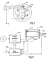
- FIG 4 An alternative method of deriving the flux signal ⁇ is shown in Figure 4, in which one or more stator poles of each phase winding 18 carries an additional winding which acts as a search coil 62.
- the search coil 62 may be wound independently of the phase winding, as shown schematically in Figure 5, or it may be wound with it in bifilar fashion. In either case, it will have a voltage induced in it when the phase winding is excited which, when integrated with respect to time by an integrator 64, gives a signal directly proportional to the flux linking the search coil 62.
- the integrated signal is fed back to the flux controller 50 as the flux feedback signal ⁇ .
- Figure 4 shows one search coil 62 for the phase winding, but it will be recognised that a system with one coil on each pole could be used or, alternatively, the coil(s) could be placed around some other part of the magnetic circuit, e.g. around the yoke of the stator core, on a section between two stator poles, where it is able to sense the flux in the magnetic circuit of the machine.
- a switched reluctance drive comprises a switched reluctance machine 110 having a stator 112 and a rotor 114 in relation to which is arranged a rotor position transducer (RPT) 116.
- the RPT 116 provides rotor position signals ⁇ to a flux controller 118 which produces firing signals for actuating a switching circuit 120 for controlling the energisation of the windings 122 associated with the stator.
- the flux controller 118 is also provided with current and supply voltage signals i and v from the machine.
- the flux controller must be able to estimate, or 'model' the flux in the machine, given the quantities of voltage, and/or current and rotor position. It is possible to achieve this in a variety of ways, two of which will be described in detail. Firstly, the flux can be modelled from a knowledge of the voltage applied to the phase and the time for which it is applied. This is called hereafter the 'voltage model'. It can be refined by introducing secondary terms involving current and winding parameters, but essentially is driven by the applied voltage. Secondly, the flux can be estimated from a knowledge of the current in the winding and the rotor position. This is called hereafter the 'current model'. While both of these models can take different analytical or numerical forms, preferred implementations will be described below.
- the flux controller 118 uses a state observer to model flux linkage, the observer including both a current model and a voltage model of the flux. It is found that the current model becomes less accurate at high speeds because of increased rotor position sensor error at high speed.
- the voltage model involves cyclical integration of voltage with respect to time and is, therefore, susceptible to errors at zero and low speeds at which the reset of the integration term occurs increasingly infrequently, leading to drift.
- the frequency response of the current model part of the flux estimating system of the embodiment is arranged so that it is dominant at zero and low speeds while the voltage model part is dominant at higher speeds.
- a search coil or bifilar winding can be arranged in relation to each phase winding, as described above in relation to Figure 4.
- ⁇ ⁇ ⁇ V / N - R * ⁇ ⁇ * R / N 2 + Kobs ⁇ * i - ⁇ ⁇ * R / N
- Kobs is the "observer gain" for the current model which is a function of rotor angular velocity ⁇ .
- R * ⁇ ⁇ * R / N 2 disappears with the use of a search coil or a bifilar winding.
- Kobs is a time domain non-linear function which is difficult to derive, but at high speed the value of Kobs will go to zero, whereas the ⁇ term contributes less at low speed.
- Kobs becomes large at low speed and dominates the observer as Kobs is based in the rotor angle domain.
- this embodiment of the invention decouples the time and angle domain terms by splitting the estimator between current and voltage models and allows each to dominate at different machine speed ranges.
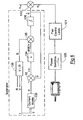
- FIG. 6 This basic technique of using both models in a closed-loop controller is shown in Figure 6, in which a current model 130 has inputs of phase current i and rotor position ⁇ . The totality of the estimator is indicated in Figure 6.
- the output of the current model 130 is an estimate of flux ⁇ i , which is fed to a summing junction 32 in which it is combined with the flux estimate ⁇ to produce a difference value ⁇ l which is provided to a gain matrix 134.
- the gain matrix 134 is a proportional-plus-integral (P+I) observer gain matrix (error convergence law).
- the observer gain matrix (error convergence law) can take other forms, such as a PD, PID, hysteretic or predictive controller as will be apparent to the skilled person.
- the voltage model 138 for the flux-creating emf E is derived from the phase voltage, phase current and phase resistance estimate.
- a thermal model to determine the phase resistance R ⁇ by estimation, or an electrical measurement of phase resistance R can be used or a combination of the two.
- a convenient form of electrical measurement would be by means of a temperature transducer, such as a thermocouple . Such a transducer will usually need a filter to attenuate noise that would otherwise lead to errors in the measurements.
- Figure 6 represents a controller for one phase of the machine. If the machine is polyphase, then each phase will essentially have a controller as shown in Figure 6, though in practice there will be some sharing of circuitry for economy.
- the closed loop flux controller will, therefore, have a high "current model gain” at low speed so the current model dominates and a low or zero current model gain at high speed where the voltage model is more suited (if the current model gain is zero, the integrators should be reset at known "zero flux” intervals).
- the current model (130 of Figure 6) could be a look up table or a functional description in the form of an algorithm.
- the advantage of the functional description is that it is amenable to adaptation via an adaptive mechanism.
- the functional description can be linear in the coefficients that change via adaptation. Even without the adaptive mechanism, the system uses both the current and voltage models to estimate flux linkage. If the system is adaptive, at low speed the phase resistance will be corrected, whereas at high speed the "current model" and potentially phase resistance will be corrected. The result is essentially no interaction of the adaptive mechanism with the flux observer.
- the voltage model is a computation of V- i*R (the flux-causing emf E) from which the flux is derived by reset integration or low pass filtering. All of the complex mutual effects are included in this calculation no matter which phase mmf is driving the flux.
- a complex look-up table, or calculation of a complex function involving all motor phase currents and rotor position, can be very computationally intensive requiring ever more computing power as the motor speed increases. This is a further reason why the current model may not be used at high speeds.
- the voltage model can be used to perform the flux estimate in isolation at high speeds.
- the voltage model does not use the shaft position to instantaneously estimate flux linkage. The increasingly inaccurate shaft position measurements/estimates with increasing motor speed (calculation delays, signal filtering delays, loss of resolution, etc.) are not of concern to the voltage model.
- FIG 7 is a more detailed three phase example of the flux control system described in Figure 6. Like reference numerals have been used for equivalent parts in Figures 6 and 7. It will be noted that each phase has separate inputs and outputs in respect of the various values of current, voltage and flux.
- the three phase SR example of the embodiment described by Figure 7 includes a closed loop flux observer having the voltage model and the current model 130 of the SR machine phase flux, which predict the flux for each phase as a function of rotor position ⁇ .
- the respective models are summed into the observer at summing junctions 135', 135" and 135"'.
- K obs observer gain matrix 134 of Figure 6 or 7, it can be any function that ensures that during low and zero speed operation ⁇ goes to zero as time (t) goes to infinity ( ⁇ n is the estimation error between the current model estimate of phase flux linkage, ⁇ In , and the complete estimate of phase flux linkages, ⁇ n ).
- K obs may be set to zero provided the integrators are reset.
- the low pass filter option may be used with zero mean AC signals for the flux-causing voltage.
- K 1 , K 2 and K 3 are dependent on the angular speed ( ⁇ ) of the rotor or are constant gains. Constant gains would be used only in a simplified implementation with reduced performance.
- K obs can be diagonal in this version of the flux observer current model to simplify calculation of K obs .
- the current model 130 estimates each phase flux linkage as a function of every phase current and angle.
- the total phase (coil) voltage is used by the voltage model portion of the flux observer.
- the integrator for the or each phase in the voltage model flux observer is reset during known periods of zero (or as near as possible zero) flux in the phase cycle.
- each integrator could also be adapted to act as a low pass filter (with, for example, time constants about 10 times longer than the fundamental frequency of the motor phase switching period) when the supply to the machine has a zero mean a.c. characteristic or a unipolar signal is transformed to a zero mean a.c. representation.
- ⁇ _I_x_tot should have only odd polynomial powers. In other words the self-induced flux linkage should have the same sign as the current that produced it.
- phase flux linkage generated by the phase current and its self-inductance
- the steel of a switched reluctance machine is a non-linear medium for flux.
- a general form of model for mutual flux linkage between phases is required.
- equations (4) through (7) include both the mutually induced flux linkages, which may be affected by mmf polarity-dependent magnetic path changes, and the self-induced flux linkages, no generalisation can be made concerning the polynomial exponents as can be made for the self-induced flux linkages in isolation.
- Equations (9) through (12) include all of the flux linkage generated in phase x that is not due to I_x alone, in other words, all of the mutual inductances. Since equations (9) through (12) describe the mutually induced flux linkages which may be affected by mmf polarity-dependent magnetic path changes, no generalisation can be made concerning the polynomial exponents as can be made for the self-induced flux linkages in isolation.
- the hyperbolic tangent is just one of a large number of functions that could be chosen. Others include spline descriptions, exponential, etc.
- the important property of the equations described is that the equations are linear in the coefficients for each poly-harmonic product term (each poly-harmonic term in equations (14) and (15) are linearly dependent on the appropriate ⁇ _x_I_x_I_y_I_z_sin_k_m_h coefficient).
- the equations being linear in their coefficients allows for least square parameter estimation. Least squares-based parameter estimation is a well proven method for adapting system models in an embedded application.
- equations (1) through (27) represent current model forms that describe a three phase SR machine, including mutual effects.
- the expressions described above in equations (1) through (3) may be used as the current model 130 of Figure 6 and equations (4) through (27) may be used as the current model 130 of Figure 7
- the model forms described by equations (1) through (27) are linear in the model coefficients and have been verified in practice. Being linear in the model coefficients allows the model forms described in equations (1) through (27) to be tuned via a Recursive Least Squares-based adaptive mechanism.
- Figure 8 illustrates an alternative flux observer.
- a matrix K o 234 is a function of phase currents i 1 , i 2 , i 3 , mechanical rotor angle ⁇ and rotor angular velocity ⁇ producing the differential flux estimate output.
- the flux estimate output of the matrix K o for each of the three phases is summed with the flux-causing voltage, as before, to derive a value of the rate of change of flux with respect to time d ⁇ ⁇ d t for each phase.
- the integral of this, from integrator 136 will be the flux observer value ⁇ for each phase.
- an inverse current model 230 describes each phase current, ( î 1 , î 2 , î 3 ), as a function of each phase flux estimate, ( ⁇ 1 , ⁇ 2 , ⁇ 3 ) and the rotor angle, ⁇ . Values of each phase current are summed with the negative of the output of the inverse current model 230, ( î 1 , î 2 , î 3 ), in a comparator 232 to produce an error signal ⁇ i n .
- the output of the inverse current model 230 is derived from the value of the three observer fluxes ( ⁇ 1 , ⁇ 2 , ⁇ 3 ) and rotor angle ( ⁇ ).
- This embodiment uses the inverse of the flux-linkage current model that was described earlier in conjunction with Figures 6 & 7.
- the inverse current model is needed (phase current estimate as a function of the phase flux or flux linkages and rotor angle) because the measured phase currents are compared with the estimated phase currents as shown in Figure 8.
- the observer is in the classic Luenberger form (see “ An Introduction to Observers", Luenberger, D.G., IEEE Translations on Automatic Control, Vol. AC-16, No. 6, December 1971, pp. 596-602 ).
- ⁇ ⁇ ⁇ V - i ⁇ ⁇ ⁇ ⁇ R + K o ⁇ i ( ⁇ , ⁇ ) - i ⁇ ( ⁇ ⁇ , ⁇ ) where î is calculated from the inverse flux linkage.
- ⁇ , ⁇ , ⁇ , i, V are all nxl vectors where n is the number of motor phases.
- the current model observer gain K o is based on a nxn matrix for an n-phase machine.
- K o - R n 0 0 0 R n 0 0 R n - K ⁇ [ f 1 i 1 ⁇ ⁇ 0 0 0 f 2 i 2 ⁇ ⁇ 0 0 0 f 3 i 3 ⁇ ⁇ ] ignoring mutual inductance.
- K o - R n 0 0 0 R n 0 0 R n - K ⁇ [ f 11 ⁇ ⁇ 12 ⁇ ⁇ 13 ⁇ ⁇ 21 ⁇ f 22 ⁇ ⁇ 23 ⁇ ⁇ 31 ⁇ ⁇ 32 ⁇ f 33 ⁇ ] i 1 i 2 i 3
- K o - R n 0 0 0 R n 0 0 R n - K ⁇ [ f 11 i 1 ⁇ ⁇ + ⁇ 123 i 1 , i 2 , i 3 , ⁇ f 22 i 2 ⁇ ⁇ + ⁇ 213 i 1 ⁇ i 2 ⁇ i 3 ⁇ ⁇ f 33 i 3 ⁇ ⁇ + f 312 i 1 ⁇ i 2 ⁇ i 3 ⁇ ]
- K o - R n 0 0 0 R n 0 0 R n - K ⁇ ⁇ ⁇ ⁇ a ⁇ i 1 , i 2 , i 3 , ⁇ i 1 ⁇ ⁇ b ⁇ i 1 , i 2 , i 3 , ⁇ i 2 ⁇ ⁇ c ⁇ i 1 , i 2 ,
- the K( ⁇ ) function has a frequency response that is typically similar to that in Figure 9, such that the K( ⁇ ) function dominates at zero and low speeds, but the voltage model dominates with increasing speed.
- the response of the current estimator will begin to tail off at about 10% to 20% of base speed, i.e. the highest speed of maximum torque output of the machine.
- the invention provides a flux control technique for electronically switched brushless machines of various types, but particularly switched reluctance machines. It produces a real-time signal estimate of the flux in the magnetic circuit of the machine to which a reference value of flux can be compared to control the machine output.
- Preferred embodiments take account of the differing considerations at high and low speeds by using a current model and a voltage model of the machine flux according to machine speed.
Landscapes
- Engineering & Computer Science (AREA)
- Power Engineering (AREA)
- Control Of Electric Motors In General (AREA)
- Control Of Motors That Do Not Use Commutators (AREA)
- Control Of Ac Motors In General (AREA)
Claims (16)
- Système de commande d'une machine à reluctance commutée, comprenant:une machine à reluctance commutée (36) comprenant un rotor (14), un stator (10) comprenant au moins une paire de pôles de stator saillants et au moins un enroulement de phase (A, B, C), l'enroulement ou chaque enroulement étant enroulé autour de la paire ou de chaque paire de pôles de stator, l'enroulement ou chaque enroulement étant agencé pour établir un flux dans un circuit magnétique dans la machine;un estimateur de flux, comprenant:des moyens, comprenant un modèle de tension (138) de la machine, agencés pour recevoir des entrées de tension de phase (V), de courant de phase (i) et une résistance d'enroulement estimée (R), pour déterminer la tension générant le flux aux bornes de l'enroulement de phase ou de chaque enroulement de phase, et pour produire un signal de rétroaction (E) représentant la tension générant le flux; etdes moyens pour dériver à partir du signal de rétroaction un signal de rétroaction de flux (ψ̂) proportionnel au flux dans l'enroulement de phase ou dans chaque enroulement de phase; etun dispositif de commande de flux (118) comprenant un signal d'entrée unique (ψD ) représentant une demande de flux de la machine, ledit dispositif de commande étant sensible au signal d'entrée et au signal de rétroaction de flux (ψ̂) pour produire des signaux de commande pour actionner les moyens de commutation pour commander le flux dans ledit au moins un enroulement de phase.
- Système selon la revendication 1, dans lequel le modèle-de tension comprend un modèle thermique de l'enroulement de phase ou de chaque enroulement de phase.
- Système selon la revendication 1 ou 2, dans lequel les moyens pour dériver le signal de flux comprennent un intégrateur agencé pour intégrer le signal de rétroaction pour produire le signal de flux.
- Système selon la revendication 3, dans lequel l'estimateur comprend des moyens pour remettre à zéro l'intégrateur en un point de courant de phase essentiellement nul pendant le cycle de l'enroulement de phase ou de chaque enroulement de phase de la machine.
- Système selon la revendication 1, dans lequel les moyens pour dériver le signal de flux comprennent un filtre passe-bas agencé pour filtrer le signal de rétroaction pour produire le signal de flux.
- Système selon l'une quelconque des revendications 1 à 4, dans lequel l'estimateur comprend un modèle de courant (130) de la machine agencé pour recevoir les signaux représentant le courant de phase et la position de rotor et pouvant être activé pour produire une estimation de flux (ψi) pour l'enroulement de phase ou chaque enroulement de phase.
- Système selon la revendication 6, dans lequel le modèle de courant comprend une estimation algébrique du flux dans l'enroulement de phase ou dans chaque enroulement de phase basé sur des entrées de courant de phase et de la position du rotor.
- Système selon l'une quelconque des revendications 6 ou 7, dans lequel l'estimateur comprend des moyens de comparaison pour produire un signal d'erreur de modèle de courant à partir de l'estimation de flux et du signal de rétroaction.
- Système selon la revendication 6, dans lequel le modèle de courant est un modèle de courant inverse (230), comprenant une estimation algébrique du courant dans l'enroulement de phase ou dans chaque enroulement de phase basée sur des entrées de la position du rotor et du flux de phase estimé.
- Système selon la revendication 9, dans lequel l'estimateur comprend des moyens de comparaison pour produire un signal d'erreur de modèle de courant inverse à partir de l'estimation de courant et du courant surveillé dans l'enroulement de phase ou dans chaque enroulement de phase.
- Système selon l'une quelconque des revendications 6 à 10, dans lequel l'estimateur comprend en outre des moyens pour additionner la sortie du modèle de tension et la sortie différentielle du modèle de courant pour produire le signal de rétroaction.
- Système selon l'une quelconque des revendications 6 à 11, dans lequel l'estimateur comprend en outre un dispositif de commande de modèle de courant agencé pour appliquer une loi de commande (134, 234) à la sortie de modèle de courant.
- Système selon la revendication 12, dans lequel le dispositif de commande de modèle de courant réagit à la vitesse de la machine de telle sorte que le signal de sortie de modèle de courant soit atténué de façon croissante avec une augmentation de la vitesse de la machine au-dessus d'une vitesse prédéterminée de la machine.
- Système selon l'une quelconque des revendications 6 à 12, comprenant des moyens pour faire en sorte que la sortie du modèle de courant domine la sortie du modèle de tension à des vitesses relativement basses de la machine, et pour faire en sorte que la sortie du modèle de tension domine la sortie du modèle de courant à des vitesses de la machine relativement élevées.
- Système selon l'une quelconque des revendications 1 à 14, dans lequel le dispositif de commande de flux comprend en outre un comparateur pour comparer le flux déterminé avec le flux demandé pour produire les signaux de commande.
- Procédé de commande d'une machine à reluctance commutée (36) comprenant un rotor (14), un stator (10) comprenant au moins une paire de pôles de stator saillants et au moins un enroulement de phase (A, B, C), l'enroulement ou chaque enroulement étant enroulé autour de la paire ou de chaque paire de pôles de stator, l'enroulement ou chaque enroulement étant agencé pour établir un flux dans un circuit magnétique dans la machine, le procédé comprenant:la production d'un signal de rétroaction de flux (ψ̂) comprenant une partie indicative de la tension générant le flux aux bornes de l'enroulement de phase ou de chaque enroulement de phase, comprenant la détermination de la tension générant le flux en utilisant un modèle de tension (138) de la machine agencé pour recevoir des entrées de tension de phase (V), de courant de phase (i) et de résistance d'enroulement estimée (R);la production d'un signal d'entrée unique (42') représentant une demande de flux de la machine; etla commande de l'excitation d'au moins un enroulement de phase en réponse au signal d'entrée et au signal de rétroaction de flux (ψ̂).
Applications Claiming Priority (2)
| Application Number | Priority Date | Filing Date | Title |
|---|---|---|---|
| GB9929994 | 1999-12-17 | ||
| GBGB9929994.3A GB9929994D0 (en) | 1999-12-17 | 1999-12-17 | Brushless machine control |
Publications (3)
| Publication Number | Publication Date |
|---|---|
| EP1109308A2 EP1109308A2 (fr) | 2001-06-20 |
| EP1109308A3 EP1109308A3 (fr) | 2003-04-23 |
| EP1109308B1 true EP1109308B1 (fr) | 2007-10-10 |
Family
ID=10866608
Family Applications (1)
| Application Number | Title | Priority Date | Filing Date |
|---|---|---|---|
| EP00310807A Expired - Lifetime EP1109308B1 (fr) | 1999-12-17 | 2000-12-05 | Commande d'un machine à reluctance commutée |
Country Status (6)
| Country | Link |
|---|---|
| US (1) | US20010010453A1 (fr) |
| EP (1) | EP1109308B1 (fr) |
| JP (1) | JP2001197777A (fr) |
| KR (1) | KR100745007B1 (fr) |
| DE (1) | DE60036679T2 (fr) |
| GB (1) | GB9929994D0 (fr) |
Cited By (1)
| Publication number | Priority date | Publication date | Assignee | Title |
|---|---|---|---|---|
| CN106872895A (zh) * | 2017-04-25 | 2017-06-20 | 天津工业大学 | 一种开关磁阻电机磁链特性检测装置及检测方法 |
Families Citing this family (15)
| Publication number | Priority date | Publication date | Assignee | Title |
|---|---|---|---|---|
| JP2001069787A (ja) * | 1999-08-30 | 2001-03-16 | Aisin Seiki Co Ltd | モ−タ駆動の制御装置 |
| GB0415166D0 (en) * | 2004-07-06 | 2004-08-11 | Switched Reluctance Drives Ltd | Rotor position detection in an electrical machine |
| FR2878662B1 (fr) * | 2004-11-30 | 2007-02-23 | Renault Sas | Procede de commande pour un fonctionnement en mode courant continu d'un ensemble d'entrainement de vehicule a moteur thermique |
| GB0520178D0 (en) * | 2005-10-04 | 2005-11-09 | Switched Reluctance Drives Ltd | Rotor position detection in an electrical machine |
| US7449859B2 (en) * | 2007-02-20 | 2008-11-11 | Gm Global Technology Operations, Inc. | Reduction of subharmonic oscillation at high frequency operation of a power inverter |
| GB0708739D0 (en) * | 2007-05-04 | 2007-06-13 | Switched Reluctance Drives Ltd | Control of a brushless electrical machine |
| GB0722919D0 (en) * | 2007-11-22 | 2008-01-02 | Switched Reluctance Drives Ltd | Deriving information on parameters in electrical machines |
| DE102011083019A1 (de) * | 2011-09-20 | 2013-03-21 | Robert Bosch Gmbh | Verfahren und Vorrichtung zur Bestimmung der Rotorposition und der Drehzahl einer Drehfeldmaschine |
| TWI695447B (zh) | 2013-11-13 | 2020-06-01 | 布魯克斯自動機械公司 | 運送設備 |
| KR102686315B1 (ko) | 2013-11-13 | 2024-07-19 | 브룩스 오토메이션 인코퍼레이티드 | 씰링된 로봇 드라이브 |
| JP2016537948A (ja) | 2013-11-13 | 2016-12-01 | ブルックス オートメーション インコーポレイテッド | 密封スイッチトリラクタンスモータ |
| US10564221B2 (en) | 2013-11-13 | 2020-02-18 | Brooks Automation, Inc. | Method and apparatus for brushless electrical machine control |
| JP6643702B2 (ja) * | 2015-11-10 | 2020-02-12 | シンフォニアテクノロジー株式会社 | ロータ位置検出装置及びモータ制御装置 |
| US10768585B2 (en) * | 2018-06-13 | 2020-09-08 | Mitsubishi Electric Research Laboratories, Inc. | System and method for data-driven control with partially unknown feedback |
| US12136897B2 (en) * | 2021-08-06 | 2024-11-05 | PAL-K Dynamics Inc. | Energy efficient motor-generator |
Family Cites Families (5)
| Publication number | Priority date | Publication date | Assignee | Title |
|---|---|---|---|---|
| JPS55106056A (en) * | 1979-02-09 | 1980-08-14 | Fuji Electric Co Ltd | Gap flux density distribution detector for synchronous machine |
| JPS591073B2 (ja) * | 1979-04-10 | 1984-01-10 | 富士電機株式会社 | 同期電動機の磁束演算器 |
| US5140244A (en) * | 1991-09-13 | 1992-08-18 | General Electric Company | Lock detector for switched reluctance machine rotor position estimator |
| GB9211685D0 (en) * | 1992-06-03 | 1992-07-15 | Switched Reluctance Drives Ltd | Sensorless rotor position measurement |
| EP1042853A2 (fr) * | 1997-11-28 | 2000-10-11 | Abb Ab | Procede et dispositif de commande du flux magnetique avec en enroulement auxiliaire dans une machine rotative electrique a courant alternatif haute tension |
-
1999
- 1999-12-17 GB GBGB9929994.3A patent/GB9929994D0/en not_active Ceased
-
2000
- 2000-12-05 DE DE60036679T patent/DE60036679T2/de not_active Expired - Lifetime
- 2000-12-05 EP EP00310807A patent/EP1109308B1/fr not_active Expired - Lifetime
- 2000-12-15 JP JP2000382709A patent/JP2001197777A/ja active Pending
- 2000-12-15 US US09/738,467 patent/US20010010453A1/en not_active Abandoned
- 2000-12-16 KR KR1020000077446A patent/KR100745007B1/ko not_active Expired - Fee Related
Non-Patent Citations (2)
| Title |
|---|
| C. WEINER: "Flux-linkage control of fully-pitched switched reluctance motors", EPE 99, LAUSANNE, pages 1 - 9 * |
| P.G. BARRAS, B.C. MECROW: "flux and torque control of switched reluctance machines", IEE PROCEDINGS, vol. 145, no. 6, 6 November 1998 (1998-11-06), pages 519 - 527 * |
Cited By (1)
| Publication number | Priority date | Publication date | Assignee | Title |
|---|---|---|---|---|
| CN106872895A (zh) * | 2017-04-25 | 2017-06-20 | 天津工业大学 | 一种开关磁阻电机磁链特性检测装置及检测方法 |
Also Published As
| Publication number | Publication date |
|---|---|
| EP1109308A2 (fr) | 2001-06-20 |
| GB9929994D0 (en) | 2000-02-09 |
| DE60036679T2 (de) | 2008-07-17 |
| DE60036679D1 (de) | 2007-11-22 |
| KR100745007B1 (ko) | 2007-08-02 |
| US20010010453A1 (en) | 2001-08-02 |
| JP2001197777A (ja) | 2001-07-19 |
| EP1109308A3 (fr) | 2003-04-23 |
| KR20010062523A (ko) | 2001-07-07 |
Similar Documents
| Publication | Publication Date | Title |
|---|---|---|
| US6731083B2 (en) | Flux feedback control system | |
| Haque et al. | A sensorless initial rotor position estimation scheme for a direct torque controlled interior permanent magnet synchronous motor drive | |
| JP3467961B2 (ja) | 回転電機の制御装置 | |
| EP0656158B1 (fr) | Procede et appareil pour determiner un parametre de deplacement de rotor | |
| US6441580B2 (en) | Brushless machine control | |
| EP1109308A2 (fr) | Régulation pour une machine sans balai | |
| CN100379142C (zh) | 交流电动机的不使用速度传感器的向量控制方法与向量控制器 | |
| EP1835613B1 (fr) | Système et procédé d'estimation de la vitesse d'un moteur utilisant un système adaptatif avec référence d'un modèle hybride | |
| US6396237B2 (en) | Position detection of switched reluctance machines | |
| EP0944164B1 (fr) | Procede de commande sans detecteur et appareil pour moteur synchrone a aimant permanent | |
| KR100795382B1 (ko) | 영구 자석 회전 머신을 무센서 방식으로 제어하는 시스템및 방법 | |
| EP1086525B1 (fr) | Reduction de la marge d'erreur du calcul de deplacement angulaire des rotors de machines synchrones | |
| EP0533413A1 (fr) | Estimateur discrète de position pour une machine à réluctance commutée avec un comparateur de mappage pour flux-courant | |
| WO1995028031A1 (fr) | Procede et appareil de regulation de moteurs a induction | |
| WO1994011945A1 (fr) | Procede de commande base sur l'observation de moteurs synchrones a aimants permanents | |
| EP0535280B1 (fr) | Système de retour de flux | |
| Hurst et al. | A self-tuning closed-loop flux observer for sensorless torque control of standard induction machines | |
| JP3473178B2 (ja) | 回転電機の制御装置 | |
| US20090134831A1 (en) | Deriving Values of Parameters in Electrical Machines | |
| Colamartino et al. | Considerations of non-sinusoidal field distribution in a permanent magnet synchronous motor control | |
| JP4061446B2 (ja) | 同期電動機の抵抗値同定方法とその制御装置 | |
| Vazifedan et al. | Sensorless control of dual stator winding induction machine drive using sliding mode control based model reference adaptive system | |
| Reddy et al. | Online Inductance Estimation of Speed Sensor less Induction Motor Drives | |
| EP2846455A1 (fr) | Procédé et appareil d'estimation d'un flux de stator dans une machine à induction électrique | |
| JP3797484B2 (ja) | ステッピングモータの駆動装置 |
Legal Events
| Date | Code | Title | Description |
|---|---|---|---|
| PUAI | Public reference made under article 153(3) epc to a published international application that has entered the european phase |
Free format text: ORIGINAL CODE: 0009012 |
|
| AK | Designated contracting states |
Kind code of ref document: A2 Designated state(s): AT BE CH CY DE DK ES FI FR GB GR IE IT LI LU MC NL PT SE TR |
|
| AX | Request for extension of the european patent |
Free format text: AL;LT;LV;MK;RO;SI |
|
| PUAL | Search report despatched |
Free format text: ORIGINAL CODE: 0009013 |
|
| AK | Designated contracting states |
Designated state(s): AT BE CH CY DE DK ES FI FR GB GR IE IT LI LU MC NL PT SE TR |
|
| AX | Request for extension of the european patent |
Extension state: AL LT LV MK RO SI |
|
| RIC1 | Information provided on ipc code assigned before grant |
Ipc: 7H 02P 7/05 A Ipc: 7H 02P 21/00 B |
|
| 17P | Request for examination filed |
Effective date: 20030924 |
|
| AKX | Designation fees paid |
Designated state(s): DE FR GB IT |
|
| 17Q | First examination report despatched |
Effective date: 20040805 |
|
| GRAP | Despatch of communication of intention to grant a patent |
Free format text: ORIGINAL CODE: EPIDOSNIGR1 |
|
| RIC1 | Information provided on ipc code assigned before grant |
Ipc: H02P 21/00 20060101ALI20070328BHEP Ipc: H02P 25/08 20060101AFI20070328BHEP |
|
| RTI1 | Title (correction) |
Free format text: SWITCHED RELUCTANCE MACHINE CONTROL |
|
| RIN1 | Information on inventor provided before grant (corrected) |
Inventor name: MARCINKIEWICZ, JOSEPH GERALD |
|
| GRAS | Grant fee paid |
Free format text: ORIGINAL CODE: EPIDOSNIGR3 |
|
| GRAA | (expected) grant |
Free format text: ORIGINAL CODE: 0009210 |
|
| AK | Designated contracting states |
Kind code of ref document: B1 Designated state(s): DE FR GB IT |
|
| REG | Reference to a national code |
Ref country code: GB Ref legal event code: FG4D |
|
| REF | Corresponds to: |
Ref document number: 60036679 Country of ref document: DE Date of ref document: 20071122 Kind code of ref document: P |
|
| ET | Fr: translation filed | ||
| PLBE | No opposition filed within time limit |
Free format text: ORIGINAL CODE: 0009261 |
|
| STAA | Information on the status of an ep patent application or granted ep patent |
Free format text: STATUS: NO OPPOSITION FILED WITHIN TIME LIMIT |
|
| 26N | No opposition filed |
Effective date: 20080711 |
|
| REG | Reference to a national code |
Ref country code: FR Ref legal event code: CD |
|
| REG | Reference to a national code |
Ref country code: DE Ref legal event code: R082 Ref document number: 60036679 Country of ref document: DE Representative=s name: UEXKUELL & STOLBERG, DE |
|
| REG | Reference to a national code |
Ref country code: DE Ref legal event code: R082 Ref document number: 60036679 Country of ref document: DE Representative=s name: UEXKUELL & STOLBERG PARTNERSCHAFT VON PATENT- , DE Effective date: 20121217 Ref country code: DE Ref legal event code: R081 Ref document number: 60036679 Country of ref document: DE Owner name: NIDEC SR DRIVES LTD., HARROGATE, GB Free format text: FORMER OWNER: SWITCHED RELUCTANCE DRIVES LTD., HARROGATE, NORTH YORKSHIRE, GB Effective date: 20121217 Ref country code: DE Ref legal event code: R082 Ref document number: 60036679 Country of ref document: DE Representative=s name: UEXKUELL & STOLBERG, DE Effective date: 20121217 Ref country code: DE Ref legal event code: R081 Ref document number: 60036679 Country of ref document: DE Owner name: NIDEC SR DRIVES LTD., GB Free format text: FORMER OWNER: SWITCHED RELUCTANCE DRIVES LTD., HARROGATE, GB Effective date: 20121217 |
|
| REG | Reference to a national code |
Ref country code: FR Ref legal event code: PLFP Year of fee payment: 16 |
|
| REG | Reference to a national code |
Ref country code: FR Ref legal event code: PLFP Year of fee payment: 17 |
|
| PGFP | Annual fee paid to national office [announced via postgrant information from national office to epo] |
Ref country code: IT Payment date: 20161219 Year of fee payment: 17 Ref country code: FR Payment date: 20161207 Year of fee payment: 17 |
|
| PGFP | Annual fee paid to national office [announced via postgrant information from national office to epo] |
Ref country code: DE Payment date: 20161222 Year of fee payment: 17 |
|
| REG | Reference to a national code |
Ref country code: DE Ref legal event code: R119 Ref document number: 60036679 Country of ref document: DE |
|
| REG | Reference to a national code |
Ref country code: FR Ref legal event code: ST Effective date: 20180831 |
|
| PG25 | Lapsed in a contracting state [announced via postgrant information from national office to epo] |
Ref country code: DE Free format text: LAPSE BECAUSE OF NON-PAYMENT OF DUE FEES Effective date: 20180703 Ref country code: FR Free format text: LAPSE BECAUSE OF NON-PAYMENT OF DUE FEES Effective date: 20180102 Ref country code: IT Free format text: LAPSE BECAUSE OF NON-PAYMENT OF DUE FEES Effective date: 20171205 |
|
| PGFP | Annual fee paid to national office [announced via postgrant information from national office to epo] |
Ref country code: GB Payment date: 20191127 Year of fee payment: 20 |
|
| REG | Reference to a national code |
Ref country code: GB Ref legal event code: PE20 Expiry date: 20201204 |
|
| PG25 | Lapsed in a contracting state [announced via postgrant information from national office to epo] |
Ref country code: GB Free format text: LAPSE BECAUSE OF EXPIRATION OF PROTECTION Effective date: 20201204 |