EP1109340A2 - Verfahren und Vorrichtung zum Auslösen einer Aufwärtsübertragung an einem richtigen Zeitpunkt - Google Patents
Verfahren und Vorrichtung zum Auslösen einer Aufwärtsübertragung an einem richtigen Zeitpunkt Download PDFInfo
- Publication number
- EP1109340A2 EP1109340A2 EP00660230A EP00660230A EP1109340A2 EP 1109340 A2 EP1109340 A2 EP 1109340A2 EP 00660230 A EP00660230 A EP 00660230A EP 00660230 A EP00660230 A EP 00660230A EP 1109340 A2 EP1109340 A2 EP 1109340A2
- Authority
- EP
- European Patent Office
- Prior art keywords
- offset
- time
- slot
- uplink transmission
- shifted
- Prior art date
- Legal status (The legal status is an assumption and is not a legal conclusion. Google has not performed a legal analysis and makes no representation as to the accuracy of the status listed.)
- Withdrawn
Links
Images
Classifications
-
- H—ELECTRICITY
- H04—ELECTRIC COMMUNICATION TECHNIQUE
- H04N—PICTORIAL COMMUNICATION, e.g. TELEVISION
- H04N7/00—Television systems
- H04N7/16—Analogue secrecy systems; Analogue subscription systems
- H04N7/173—Analogue secrecy systems; Analogue subscription systems with two-way working, e.g. subscriber sending a programme selection signal
- H04N7/17309—Transmission or handling of upstream communications
-
- H—ELECTRICITY
- H04—ELECTRIC COMMUNICATION TECHNIQUE
- H04H—BROADCAST COMMUNICATION
- H04H60/00—Arrangements for broadcast applications with a direct linking to broadcast information or broadcast space-time; Broadcast-related systems
- H04H60/76—Arrangements characterised by transmission systems other than for broadcast, e.g. the Internet
- H04H60/81—Arrangements characterised by transmission systems other than for broadcast, e.g. the Internet characterised by the transmission system itself
- H04H60/93—Wired transmission systems
- H04H60/96—CATV systems
- H04H60/97—CATV systems using uplink of the CATV systems
-
- H—ELECTRICITY
- H04—ELECTRIC COMMUNICATION TECHNIQUE
- H04J—MULTIPLEX COMMUNICATION
- H04J3/00—Time-division multiplex systems
- H04J3/02—Details
- H04J3/06—Synchronising arrangements
- H04J3/0635—Clock or time synchronisation in a network
- H04J3/0682—Clock or time synchronisation in a network by delay compensation, e.g. by compensation of propagation delay or variations thereof, by ranging
-
- H—ELECTRICITY
- H04—ELECTRIC COMMUNICATION TECHNIQUE
- H04J—MULTIPLEX COMMUNICATION
- H04J3/00—Time-division multiplex systems
- H04J3/16—Time-division multiplex systems in which the time allocation to individual channels within a transmission cycle is variable, e.g. to accommodate varying complexity of signals, to vary number of channels transmitted
- H04J3/1694—Allocation of channels in TDM/TDMA networks, e.g. distributed multiplexers
-
- H—ELECTRICITY
- H04—ELECTRIC COMMUNICATION TECHNIQUE
- H04N—PICTORIAL COMMUNICATION, e.g. TELEVISION
- H04N21/00—Selective content distribution, e.g. interactive television or video on demand [VOD]
- H04N21/20—Servers specifically adapted for the distribution of content, e.g. VOD servers; Operations thereof
- H04N21/25—Management operations performed by the server for facilitating the content distribution or administrating data related to end-users or client devices, e.g. end-user or client device authentication, learning user preferences for recommending movies
- H04N21/262—Content or additional data distribution scheduling, e.g. sending additional data at off-peak times, updating software modules, calculating the carousel transmission frequency, delaying a video stream transmission, generating play-lists
- H04N21/26208—Content or additional data distribution scheduling, e.g. sending additional data at off-peak times, updating software modules, calculating the carousel transmission frequency, delaying a video stream transmission, generating play-lists the scheduling operation being performed under constraints
- H04N21/26241—Content or additional data distribution scheduling, e.g. sending additional data at off-peak times, updating software modules, calculating the carousel transmission frequency, delaying a video stream transmission, generating play-lists the scheduling operation being performed under constraints involving the time of distribution, e.g. the best time of the day for inserting an advertisement or airing a children programme
Definitions
- the invention concerns generally the technology of determining the correct transmission moment for a scheduled uplink transmission. Especially the invention concerns such determination in an arrangement where the transmission moment is scheduled in relation to a certain regular synchronization signal.
- the European Telecommunications Standard number ETS 300 800 known also as the DVB-RC (Digital Video Broadcasting - Return Channel) standard and compliant with the DAVIC (Digital Audio-Visual Council) 1.4 standard, lays down the general framework for implementing an uplink transmission channel as a part of bidirectional communication over a cable television network.
- An apparatus known as the cable modem which is a basically known part of the terminal arrangement located at e.g. a private home, is allowed to emit transmissions in the uplink direction according to a certain schedule.
- a centrally located device known as the head-end composes the uplink transmission schedule and communicates the allocated uplink transmission time intervals to the cable modems.
- the messages that comprise these allocations are known as MAC or Media Access Control messages, and they are complemented by the information of MAC Flags included in the downlink transmission.
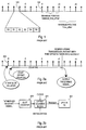
- Fig. 1 illustrates some known aspects of the timing of the uplink transmissions.
- the downlink transmission which the cable modems are listening to contains a synchronization signal which comprises time indicators or markers 101 that occur regularly with one or three millisecond intervals.
- the downlink transmission may come either in an out-of-band (OOB) or in-band (IB) form, which makes a small difference to the implementation of the markers 101.
- OOB downlink transmission consists of a continuous stream of downlink data structures known as SL-ESFs (Signalling Link Extended Superframes). Each SL-ESF contains 4632 bits, of which bits number 0, 1544 and 3088 are available as marker bits.
- An IB downlink transmission consists of so-called MPEG2-TS packets where a certain upstream slot marker pointer indicates the number of symbol clock cycles between the first symbol of the next synchronization byte and the next 3 ms marker.
- the upstream data rate may be 256 kbit/s, 1.544 Mbit/s, 3.088 Mbit/s or 6.176 Mbit/s, corresponding to slot rates of 500, 3000, 6000 or 12 000 upstream slots/s respectively. If we consider the markers to occur at 1 ms intervals, each time interval between two successive markers 101 may comprise half, three, six or twelve allocatable uplink transmission slots. In Fig. 1 the division of one such time interval into six uplink slots S0 to S5 is shown as an example.
- the upstream slots are numbered according to a certain cyclic numbering scheme which is derived from the downstream frame numbers which are included in the downstream frames.
- the downlink frames comprise a set of so-called M-bits M10 - M1 which constitute a register the value of which is incremented by one every 3 ms.
- the maximum value for the register is calculable from a certain MAC Default Configuration element and the upstream data rate. After the maximum value the register returns to zero.
- the upstream slot numbers that are valid during a certain 3 ms period are calculated from the register value received during the immediately preceding 3 ms period by multiplying the register value with integer multipliers which are associated with the upstream data rate.
- the head-end When the head-end wants to assign an uplink transmission slot to a certain cable modem, it transmits a certain MAC Connect message where it uses a specific indication scheme to announce to the cable modem the first upstream slot number in which it may begin transmitting, the number of successive assigned slots following the first slot, the cyclic or listed occurrence of following similar slot allocations and the last slot number which the cable modem may use for uplink transmissions. Because the uplink slot numbers are defined in relation to downlink frame numbers, and because the uplink slot positions are synchronized to the markers given within the downlink frames, the cable modem has thereafter all the information it needs to trigger its uplink transmission(s) at exactly given moment(s).
- the assignment of a certain uplink slot determines a certain marker to be used as a reference point.
- This marker has been designated in Fig. 1 as the zero point 102 in the time base laid down by the markers.
- the defined maximum ranges of the Absolute_time_offset and Time_offset indicators mean that the actual transmission moment or the allocated uplink slot may be located anywhere within the 12 millisecond interval which lies symmetrically around the reference point 102. It is on the responsibility of the cable modem to decode the allocation of its uplink transmission slot and to trigger the uplink transmission so that it takes place within the limits of the allocated slot.
- the range of available offsets may be shorter on the negative offset side (to the left from the reference point 102 in Fig. 1) than 6 milliseconds, because the MAC message / MAC Flags that contains the allocation may come less than 6 milliseconds before the time indicator that is used as the reference point.
- the cable modem in order to fulfil the standard's requirements the cable modem must be able to time its uplink transmission to any point of time within said 12 ms interval, with offset timing steps of 100 nanoseconds, as defined by the head-end.
- the required accuracy in triggering the uplink transmission is ⁇ 0.625 symbol durations with selected transmission rate.
- a microprocessor controls all operations of the cable modem, so in principle it would be possible to instruct the microprocessor to generate a triggering signal to the uplink transmitter in the cable modem so that the uplink transmission would take place exactly at a given moment.
- a known hardware-based solution is to have in the cable modem a slot counter that is synchronized to the actual occurrence of the markers seen by the cable modem. In other words the slot counter does not take into account the offset values (the Absolute_time_offset and Time_offset indicators). Additionally a known cable modem contains a number of offset counters. Each offset counter ticks at steps of 100 ns throughout the whole 12 ms interval described above if required. Each offset counter is initialized to give a transmission triggering signal at a time instant that differs from the nominal position of an allocated slot by a time which corresponds to the given Absolute_time_offset and Time_offset values.
- Figs. 2a and 2b illustrate the principles of the above-described conventional hardware-based solution.
- Each offset counter in the offset counter block 201 is reset with an initialization instruction that makes the counter to expire after the combined length of time given by the Absolute_time_offset and Time_offset indicators.
- the slot counter 203 counts all the time and is synchronized to the markers, of which there is specificallyt shown a marker 202 that marks the beginning of the 12 ms interval referred to above.
- an offset counter is started: when that offset counter expires, it gives an expiration signal which acts as the triggering instruction to the uplink transmitter 204.
- the objects of the invention are achieved by using a two-stage counter where a first stage shifts the slot counting in relation to the synchronization pulses and the second stage determines a certain time slot in the shifted slot counting domain.
- the method according to the invention is characterized in that it comprises the steps of
- the invention applies to a cable modem which is characterized in that it comprises
- the size of the offset counter that shifts the slot counting scheme, as well as the accuracy required from it, may be kept at a minimum if the offset timing is reduced to the shortest possible time interval that still contains a marker received from the head-end.
- the absolute offset sum given by the Absolute_time_offset and Time_offset indicators may be as large as 6 milliseconds, it suffices to have an offset counter the maximum range of which equals the time interval between successive markers, i.e. 1 millisecond.
- the number of integer milliseconds deducted from the absolute offset sum given by the Absolute_time_offset and Time_offset indicators is compensated for in the initialization of the slot counter.
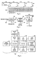
- Fig. 3 illustrates a timing principle where the timebase is determined by the regularly occurring time indicators 301.
- the invention does not require the applicability of especially the DVB-RC or DAVIC 1.4 standards, but for consistency of description we may assume that the time indicators 301 are the markers that come with constant 1 ms intervals in the downlink direction from a head-end.
- the range within which the timing of any number of uplink transmissions must be determined covers symmetrically 6 time indicator intervals to the positive and negative directions from a certain zero point.
- Fig. 3 does not as such determine any particular time indicator as the zero point.
- a certain shifted time indicator 302 and subsequent other shifted time indicators 303 which are the synchronization points for a shifted slot counter 304.
- the upmost line in the shifted slot counter illustrates certain slot numbers on an uplink channel of 1.544 Mbit/s
- the middle line illustrates corresponding slot numbers on an uplink channel of 3.088 Mbit/s
- the lowest line illustrates corresponding slot numbers on an uplink channel of 6.176 Mbit/s.
- the location in time of the shifted time indicator 302 in relation to the actually occurring time indicators 301 is such that between an immediately preceding actual time indicator 301 and the shifted time indicator 302 there is an offset interval that is shorter than one millisecond.
- the length of the offset interval comes from the Absolute_time_offset and Time_offset indicators in the following way.
- the Absolute_time_offset and Time_offset indicators together give a certain total offset value which may be anything between -6 milliseconds and +6 milliseconds at steps of 100 nanoseconds. If the total offset value is zero, also the offset interval shown in Fig. 3 is zero and the shifted slot counter is synchronized to the actually occurring time indicators 301. If the total offset value is positive, the offset interval shown in Fig. 3 is equal to the decimal remainder of the total offset value. If the total offset value is negative, the offset interval shown in Fig. 3 is equal to one minus the absolute decimal remainder of the total offset value.
- the "decimal remainder" definition of the offset interval means that the number of integer milliseconds in the total offset value must be accounted for in the initialization of the shifted slot counter 304. For example, if the number of integer milliseconds in the total offset value is three, the slot numbers given by the shifted slot counter must refer to an M-bit register value which is one less than if the total offset value would be between zero and one millisecond. Generally if the number of integer milliseconds in the total offset value is n, the slot numbers given by the shifted slot counter must refer to an M-bit register value which is obtained by deducting a certain datarate-dependent value (e.g. n/3) from the M-bit register value which they would refer to without the shifting (since the M-bit register value only changes by 3 ms intervals).
- a certain datarate-dependent value e.g. n/3
- Fig. 4 illustrates a very simple hardware implementation that can be applied to realize the principle shown in Fig. 3.
- An offset counter 401 is arranged to receive the actually occurring time indicators along a first input line 402.
- Another input line 403 is used to initialize the offset counter 401 so that it generates the offset interval shown in Fig. 3 and described above.
- the output of the offset counter 401 is a train of shifted time indicators which is coupled to a first input line 404 of a shifted slot counter 405.
- Also to the latter there is another input line 406 which is used to set the slot numbering in order to take into account the number of integer milliseconds in the total offset value.
- the shifted slot counter 405 gives at its output 407 a running slot number which includes a shift in relation to the actually occurring time indicators.
- the shift takes into account the total offset value given by the Absolute_time_offset and Time_offset indicators.
- the shifted slot numbers are coupled into a slot comparator 408 which knows the numbers of the slots which have been allocated to the cable modem for uplink transmissions.
- the allocations have been programmed into the slot comparator 408 through a programming input 409. Whenever a shifted slot number coming from the shifted slot counter 405 coincides with the number of an allocated uplink transmission slot, the slot comparator 408 gives a triggering signal at its output 410.
- Fig. 5 illustrates schematically a cable modem according to an embodiment of the invention.
- a bidirectional cable network interface 501 connects the cable modem to a cable network, which is not as such shown in Fig. 5.
- a duplexing block 502 is used to separate downlink and uplink transmissions from each other. Downlink transmissions are directed from the duplexing block 502 to a receiving, demodulating and decoding block 503 which converts the downlink transmission into a digital bit stream on the baseband frequency. This digital bit stream is lead into a downlink demultiplexer 504 which operates under the command of a control block 505.
- the demultiplexer distributes the different parts of the received downlink transmission so that e.g. a television program or other real-time presentation which is meant to be reproduced immediately is directed to the corresponding presentation device 506, downlink data transmissions are directed to a local data terminal 507 and control information like uplink transmission time allocations are directed to the control block 505.
- a user input device 508 which means generally any input means that are available for a user to provide digital information that is to be transmitted in the uplink direction.
- An uplink multiplexer 509 receives inputs from said user input device 508 as well as from the local data terminal 507 and the control block 505. It composes a multiplexed uplink transmission bit stream which is fed into an uplink transmitter 510. Any coding, scrambling or other signal processing operations that are needed may be performed in either of blocks 509 and 510.
- the uplink transmission triggering block 511 is the part of the cable modem 500 which is mostly affected by the invention. Most advantageously it is of the type shown in Fig. 4. It receives the time indicators from the receiving, demodulating and decoding block 503 and initialization information from the control block 505. Using the notation of Fig. 4, line 402 comes from block 503 and lines 403, 406 and 409 come from block 505. The output of the uplink transmission triggering block 511 is coupled to the uplink transmitter 510 in order to trigger the uplink transmissions at the correct time instant.
- One alternative embodiment of the invention might be based on picking the time indicator that constitutes the first synchronization point to the shifted slot counter so that it is always at least one complete time indicator interval before the starting point of the shifted slot counter but not more that N complete time indicator intervals before it, where the positive integer N ⁇ 12.
- the offset interval shown in Fig. 3 would be always longer than 1 ms.
- a longer offset means that the offset counter becomes bigger and its required accuracy becomes higher.
- Another alternative embodiment could make the slot comparator to take into account the number of integer milliseconds in the total offset value instead of the shifted slot counter: in the programming of the slot comparator a deduction of n/3 would be made from each allocated slot number for n integer milliseconds in the total offset value.
Landscapes
- Engineering & Computer Science (AREA)
- Signal Processing (AREA)
- Computer Networks & Wireless Communication (AREA)
- Multimedia (AREA)
- Business, Economics & Management (AREA)
- Marketing (AREA)
- Databases & Information Systems (AREA)
- Synchronisation In Digital Transmission Systems (AREA)
- Small-Scale Networks (AREA)
- Time-Division Multiplex Systems (AREA)
Applications Claiming Priority (2)
| Application Number | Priority Date | Filing Date | Title |
|---|---|---|---|
| FI992718 | 1999-12-17 | ||
| FI992718A FI19992718L (fi) | 1999-12-17 | 1999-12-17 | Menetelmä ja laite ylössuuntaisen lähetyksen oikea-aikaiseksi liipaisemiseksi |
Publications (2)
| Publication Number | Publication Date |
|---|---|
| EP1109340A2 true EP1109340A2 (de) | 2001-06-20 |
| EP1109340A3 EP1109340A3 (de) | 2005-04-06 |
Family
ID=8555767
Family Applications (1)
| Application Number | Title | Priority Date | Filing Date |
|---|---|---|---|
| EP00660230A Withdrawn EP1109340A3 (de) | 1999-12-17 | 2000-12-15 | Verfahren und Vorrichtung zum Auslösen einer Aufwärtsübertragung an einem richtigen Zeitpunkt |
Country Status (3)
| Country | Link |
|---|---|
| US (1) | US7039071B2 (de) |
| EP (1) | EP1109340A3 (de) |
| FI (1) | FI19992718L (de) |
Families Citing this family (13)
| Publication number | Priority date | Publication date | Assignee | Title |
|---|---|---|---|---|
| US7194556B2 (en) * | 2001-03-30 | 2007-03-20 | Intel Corporation | Method and apparatus for high accuracy distributed time synchronization using processor tick counters |
| US7970368B2 (en) * | 2002-02-07 | 2011-06-28 | Qualcomm Incorporated | Wired cellular telephone system |
| US7062252B2 (en) * | 2003-04-14 | 2006-06-13 | Qualcomm, Incorporated | Capacity optimization of a wired cellular network |
| US7742581B2 (en) | 2004-11-24 | 2010-06-22 | Value-Added Communications, Inc. | Electronic messaging exchange |
| US9282188B2 (en) | 2005-01-28 | 2016-03-08 | Value-Added Communications, Inc. | Voice message exchange |
| US9876915B2 (en) | 2005-01-28 | 2018-01-23 | Value-Added Communications, Inc. | Message exchange |
| KR101350441B1 (ko) * | 2007-09-27 | 2014-01-23 | 삼성전자주식회사 | 무선 통신 시스템에서 상향링크 송신 타이밍 추정 방법 및장치 |
| US9621714B2 (en) | 2009-01-27 | 2017-04-11 | Value-Added Communications, Inc. | System and method for electronic notification in institutional communication |
| GB2487027A (en) * | 2009-10-23 | 2012-07-04 | Cadio Inc | Analyzing consumer behavior using electronically-captured consumer location data |
| US10749827B2 (en) | 2017-05-11 | 2020-08-18 | Global Tel*Link Corporation | System and method for inmate notification and training in a controlled environment facility |
| CN112911539B (zh) * | 2019-11-19 | 2022-07-29 | 上海朗帛通信技术有限公司 | 一种被用于无线通信的方法和设备 |
| CN117413591A (zh) * | 2021-09-30 | 2024-01-16 | Oppo广东移动通信有限公司 | 无线通信的方法、终端设备和网络设备 |
| US12461887B1 (en) * | 2024-08-22 | 2025-11-04 | Credo Technology Group Limited | PCIe retimer with reduced power low latency mode |
Family Cites Families (9)
| Publication number | Priority date | Publication date | Assignee | Title |
|---|---|---|---|---|
| US5666358A (en) | 1995-10-16 | 1997-09-09 | General Instrument Corporation Of Delaware | Method and apparatus for supporting TDMA operating over hybrid fiber coaxial (HFC) or other channels |
| US5793772A (en) | 1995-11-29 | 1998-08-11 | Motorola, Inc. | Method and apparatus for synchronizing timing of components of a telecommunication system |
| FI101665B (fi) | 1996-08-23 | 1998-07-31 | Nokia Multimedia Network Termi | Parannettu kaksisuuntainen tietoliikenneyhteys kaapelitelevisiojärjest elmässä |
| FI101666B1 (fi) * | 1996-11-29 | 1998-07-31 | Nokia Multimedia Network Terminals Oy | Viivekriittisten palvelujen toteutus kaapelitelevisiojärjestelmässä |
| US5943604A (en) | 1997-10-31 | 1999-08-24 | Cisco Technology, Inc. | Echo device method for locating upstream ingress noise gaps at cable television head ends |
| FR2775404A1 (fr) * | 1998-02-25 | 1999-08-27 | Philips Electronics Nv | Systeme interactif de distribution de signaux audio-video numeriques |
| US6526070B1 (en) * | 1999-10-09 | 2003-02-25 | Conexant Systems, Inc. | Method and apparatus for upstream burst transmissions synchronization in cable modems |
| US6698022B1 (en) * | 1999-12-15 | 2004-02-24 | Fujitsu Limited | Timestamp-based timing recovery for cable modem media access controller |
| JP3462471B2 (ja) * | 2001-01-19 | 2003-11-05 | 株式会社日立製作所 | 無線基地局の送信タイミングのオフセット測定方法及びオフセット測定装置 |
-
1999
- 1999-12-17 FI FI992718A patent/FI19992718L/fi unknown
-
2000
- 2000-12-13 US US09/736,111 patent/US7039071B2/en not_active Expired - Fee Related
- 2000-12-15 EP EP00660230A patent/EP1109340A3/de not_active Withdrawn
Also Published As
| Publication number | Publication date |
|---|---|
| FI19992718A7 (fi) | 2001-06-18 |
| EP1109340A3 (de) | 2005-04-06 |
| FI19992718L (fi) | 2001-06-18 |
| US7039071B2 (en) | 2006-05-02 |
| US20010005907A1 (en) | 2001-06-28 |
Similar Documents
| Publication | Publication Date | Title |
|---|---|---|
| US7039071B2 (en) | Method and device for triggering an uplink transmission at a correct time instant | |
| CA1316236C (en) | Method of and circuit arrangement for synchronizing a digital data transmission arrangement with a network-external clock | |
| EP1222759B1 (de) | Verfahren und vorrichtung zur synchronisierung von aufwärtsburstübertragungen in kabelmodems | |
| US5351239A (en) | Digital data transmission system | |
| KR910001743B1 (ko) | 데이타 멀티 플렉스 전송 장치 | |
| EP0540452A1 (de) | Verfahren und Gerät zum Transformieren von Übertragungs-Kanälen mit niedrige Bandbreite zum Kanal mit grosser Bandbreite | |
| KR970024672A (ko) | 하이브리드 파이버 동축 또는 다른 채널상에서의 시분할 다중 액세스 동작을 지원하는 방법 및 장치 | |
| UA45984C2 (uk) | Спосіб усунення переповнення або втрати значущості буфера і пристрій для його здійснення | |
| US6091440A (en) | Implementation of delay-critical services in a cable television system | |
| US4757521A (en) | Synchronization method and apparatus for a telephone switching system | |
| JP3246872B2 (ja) | バイト整列およびフレーム同期装置 | |
| EP0658990A1 (de) | Verfahren und Vorrichtung zum Ausrichten von digitalen Nachrichtenpaketen | |
| CA2037289C (en) | Single circuit for detecting a frame synchronization pattern and generating control signals | |
| JPH03157032A (ja) | 時分割多重化法を用いた多重チャンネルマルチポイントネットワーク | |
| JPH0824296B2 (ja) | 情報伝送システムにおける局間遅延調整方法 | |
| US6198736B1 (en) | Telecommunications system | |
| JP3029343B2 (ja) | 移動通信における基地局間tdmaフレーム同期方式 | |
| US5524107A (en) | Multiport multidrop digital system | |
| EP0279503A2 (de) | Zeitmultiplexsignalisierung | |
| JP3078183B2 (ja) | データ受信装置 | |
| EP0728389A1 (de) | Verfahren zum empfang eines signals in einem synchronen digitalen telekommunikationssystem | |
| JP3246423B2 (ja) | 網同期装置 | |
| KR0154465B1 (ko) | 동기망에 있어서 프레임에 따른 타임슬롯의 윈도우제어장치 | |
| JP2545538B2 (ja) | 時分割多重化伝送方法 | |
| KR100216538B1 (ko) | Mpeg-2 트랜스포트-스트림의 dvb-스크램블링 장치 |
Legal Events
| Date | Code | Title | Description |
|---|---|---|---|
| PUAI | Public reference made under article 153(3) epc to a published international application that has entered the european phase |
Free format text: ORIGINAL CODE: 0009012 |
|
| AK | Designated contracting states |
Kind code of ref document: A2 Designated state(s): AT BE CH CY DE DK ES FI FR GB GR IE IT LI LU MC NL PT SE TR |
|
| AX | Request for extension of the european patent |
Free format text: AL;LT;LV;MK;RO;SI |
|
| RAP1 | Party data changed (applicant data changed or rights of an application transferred) |
Owner name: NOKIA CORPORATION |
|
| PUAL | Search report despatched |
Free format text: ORIGINAL CODE: 0009013 |
|
| AK | Designated contracting states |
Kind code of ref document: A3 Designated state(s): AT BE CH CY DE DK ES FI FR GB GR IE IT LI LU MC NL PT SE TR |
|
| AX | Request for extension of the european patent |
Extension state: AL LT LV MK RO SI |
|
| RIC1 | Information provided on ipc code assigned before grant |
Ipc: 7H 04N 7/173 B Ipc: 7H 04J 3/06 B Ipc: 7H 04J 3/16 A |
|
| AKX | Designation fees paid | ||
| REG | Reference to a national code |
Ref country code: DE Ref legal event code: 8566 |
|
| STAA | Information on the status of an ep patent application or granted ep patent |
Free format text: STATUS: THE APPLICATION IS DEEMED TO BE WITHDRAWN |
|
| 18D | Application deemed to be withdrawn |
Effective date: 20051007 |