EP1109409A2 - Digitale Signalcodierung mit fliesenartiger Unterteilung - Google Patents
Digitale Signalcodierung mit fliesenartiger Unterteilung Download PDFInfo
- Publication number
- EP1109409A2 EP1109409A2 EP00403475A EP00403475A EP1109409A2 EP 1109409 A2 EP1109409 A2 EP 1109409A2 EP 00403475 A EP00403475 A EP 00403475A EP 00403475 A EP00403475 A EP 00403475A EP 1109409 A2 EP1109409 A2 EP 1109409A2
- Authority
- EP
- European Patent Office
- Prior art keywords
- partitioning
- signal
- division
- image
- modification
- Prior art date
- Legal status (The legal status is an assumption and is not a legal conclusion. Google has not performed a legal analysis and makes no representation as to the accuracy of the status listed.)
- Withdrawn
Links
- 238000000638 solvent extraction Methods 0.000 claims abstract description 135
- 238000000034 method Methods 0.000 claims abstract description 53
- 230000004048 modification Effects 0.000 claims abstract description 26
- 238000012986 modification Methods 0.000 claims abstract description 26
- 238000012545 processing Methods 0.000 claims description 9
- 230000000694 effects Effects 0.000 claims description 5
- 238000013519 translation Methods 0.000 claims description 4
- 230000006835 compression Effects 0.000 description 6
- 238000007906 compression Methods 0.000 description 6
- 230000004044 response Effects 0.000 description 6
- 238000005192 partition Methods 0.000 description 5
- 238000004891 communication Methods 0.000 description 4
- 238000000354 decomposition reaction Methods 0.000 description 4
- 230000005540 biological transmission Effects 0.000 description 2
- 238000001914 filtration Methods 0.000 description 2
- 238000004088 simulation Methods 0.000 description 2
- 238000012360 testing method Methods 0.000 description 2
- 230000015572 biosynthetic process Effects 0.000 description 1
- 239000003086 colorant Substances 0.000 description 1
- 238000002059 diagnostic imaging Methods 0.000 description 1
- 238000000605 extraction Methods 0.000 description 1
- 230000006870 function Effects 0.000 description 1
- 238000003384 imaging method Methods 0.000 description 1
- 230000003993 interaction Effects 0.000 description 1
- 230000002093 peripheral effect Effects 0.000 description 1
- 230000008569 process Effects 0.000 description 1
- 238000013139 quantization Methods 0.000 description 1
- 230000005236 sound signal Effects 0.000 description 1
- 230000000007 visual effect Effects 0.000 description 1
Images








Classifications
-
- H—ELECTRICITY
- H04—ELECTRIC COMMUNICATION TECHNIQUE
- H04N—PICTORIAL COMMUNICATION, e.g. TELEVISION
- H04N19/00—Methods or arrangements for coding, decoding, compressing or decompressing digital video signals
- H04N19/90—Methods or arrangements for coding, decoding, compressing or decompressing digital video signals using coding techniques not provided for in groups H04N19/10-H04N19/85, e.g. fractals
- H04N19/98—Adaptive-dynamic-range coding [ADRC]
-
- H—ELECTRICITY
- H04—ELECTRIC COMMUNICATION TECHNIQUE
- H04N—PICTORIAL COMMUNICATION, e.g. TELEVISION
- H04N19/00—Methods or arrangements for coding, decoding, compressing or decompressing digital video signals
- H04N19/10—Methods or arrangements for coding, decoding, compressing or decompressing digital video signals using adaptive coding
- H04N19/102—Methods or arrangements for coding, decoding, compressing or decompressing digital video signals using adaptive coding characterised by the element, parameter or selection affected or controlled by the adaptive coding
- H04N19/119—Adaptive subdivision aspects, e.g. subdivision of a picture into rectangular or non-rectangular coding blocks
-
- H—ELECTRICITY
- H04—ELECTRIC COMMUNICATION TECHNIQUE
- H04N—PICTORIAL COMMUNICATION, e.g. TELEVISION
- H04N19/00—Methods or arrangements for coding, decoding, compressing or decompressing digital video signals
- H04N19/10—Methods or arrangements for coding, decoding, compressing or decompressing digital video signals using adaptive coding
- H04N19/102—Methods or arrangements for coding, decoding, compressing or decompressing digital video signals using adaptive coding characterised by the element, parameter or selection affected or controlled by the adaptive coding
- H04N19/12—Selection from among a plurality of transforms or standards, e.g. selection between discrete cosine transform [DCT] and sub-band transform or selection between H.263 and H.264
- H04N19/122—Selection of transform size, e.g. 8x8 or 2x4x8 DCT; Selection of sub-band transforms of varying structure or type
-
- H—ELECTRICITY
- H04—ELECTRIC COMMUNICATION TECHNIQUE
- H04N—PICTORIAL COMMUNICATION, e.g. TELEVISION
- H04N19/00—Methods or arrangements for coding, decoding, compressing or decompressing digital video signals
- H04N19/10—Methods or arrangements for coding, decoding, compressing or decompressing digital video signals using adaptive coding
- H04N19/134—Methods or arrangements for coding, decoding, compressing or decompressing digital video signals using adaptive coding characterised by the element, parameter or criterion affecting or controlling the adaptive coding
- H04N19/154—Measured or subjectively estimated visual quality after decoding, e.g. measurement of distortion
-
- H—ELECTRICITY
- H04—ELECTRIC COMMUNICATION TECHNIQUE
- H04N—PICTORIAL COMMUNICATION, e.g. TELEVISION
- H04N19/00—Methods or arrangements for coding, decoding, compressing or decompressing digital video signals
- H04N19/10—Methods or arrangements for coding, decoding, compressing or decompressing digital video signals using adaptive coding
- H04N19/134—Methods or arrangements for coding, decoding, compressing or decompressing digital video signals using adaptive coding characterised by the element, parameter or criterion affecting or controlling the adaptive coding
- H04N19/162—User input
-
- H—ELECTRICITY
- H04—ELECTRIC COMMUNICATION TECHNIQUE
- H04N—PICTORIAL COMMUNICATION, e.g. TELEVISION
- H04N19/00—Methods or arrangements for coding, decoding, compressing or decompressing digital video signals
- H04N19/10—Methods or arrangements for coding, decoding, compressing or decompressing digital video signals using adaptive coding
- H04N19/169—Methods or arrangements for coding, decoding, compressing or decompressing digital video signals using adaptive coding characterised by the coding unit, i.e. the structural portion or semantic portion of the video signal being the object or the subject of the adaptive coding
- H04N19/17—Methods or arrangements for coding, decoding, compressing or decompressing digital video signals using adaptive coding characterised by the coding unit, i.e. the structural portion or semantic portion of the video signal being the object or the subject of the adaptive coding the unit being an image region, e.g. an object
-
- H—ELECTRICITY
- H04—ELECTRIC COMMUNICATION TECHNIQUE
- H04N—PICTORIAL COMMUNICATION, e.g. TELEVISION
- H04N19/00—Methods or arrangements for coding, decoding, compressing or decompressing digital video signals
- H04N19/10—Methods or arrangements for coding, decoding, compressing or decompressing digital video signals using adaptive coding
- H04N19/169—Methods or arrangements for coding, decoding, compressing or decompressing digital video signals using adaptive coding characterised by the coding unit, i.e. the structural portion or semantic portion of the video signal being the object or the subject of the adaptive coding
- H04N19/17—Methods or arrangements for coding, decoding, compressing or decompressing digital video signals using adaptive coding characterised by the coding unit, i.e. the structural portion or semantic portion of the video signal being the object or the subject of the adaptive coding the unit being an image region, e.g. an object
- H04N19/176—Methods or arrangements for coding, decoding, compressing or decompressing digital video signals using adaptive coding characterised by the coding unit, i.e. the structural portion or semantic portion of the video signal being the object or the subject of the adaptive coding the unit being an image region, e.g. an object the region being a block, e.g. a macroblock
-
- H—ELECTRICITY
- H04—ELECTRIC COMMUNICATION TECHNIQUE
- H04N—PICTORIAL COMMUNICATION, e.g. TELEVISION
- H04N19/00—Methods or arrangements for coding, decoding, compressing or decompressing digital video signals
- H04N19/60—Methods or arrangements for coding, decoding, compressing or decompressing digital video signals using transform coding
- H04N19/63—Methods or arrangements for coding, decoding, compressing or decompressing digital video signals using transform coding using sub-band based transform, e.g. wavelets
-
- H—ELECTRICITY
- H04—ELECTRIC COMMUNICATION TECHNIQUE
- H04N—PICTORIAL COMMUNICATION, e.g. TELEVISION
- H04N19/00—Methods or arrangements for coding, decoding, compressing or decompressing digital video signals
- H04N19/60—Methods or arrangements for coding, decoding, compressing or decompressing digital video signals using transform coding
- H04N19/63—Methods or arrangements for coding, decoding, compressing or decompressing digital video signals using transform coding using sub-band based transform, e.g. wavelets
- H04N19/635—Methods or arrangements for coding, decoding, compressing or decompressing digital video signals using transform coding using sub-band based transform, e.g. wavelets characterised by filter definition or implementation details
-
- H—ELECTRICITY
- H04—ELECTRIC COMMUNICATION TECHNIQUE
- H04N—PICTORIAL COMMUNICATION, e.g. TELEVISION
- H04N19/00—Methods or arrangements for coding, decoding, compressing or decompressing digital video signals
- H04N19/60—Methods or arrangements for coding, decoding, compressing or decompressing digital video signals using transform coding
- H04N19/63—Methods or arrangements for coding, decoding, compressing or decompressing digital video signals using transform coding using sub-band based transform, e.g. wavelets
- H04N19/64—Methods or arrangements for coding, decoding, compressing or decompressing digital video signals using transform coding using sub-band based transform, e.g. wavelets characterised by ordering of coefficients or of bits for transmission
- H04N19/645—Methods or arrangements for coding, decoding, compressing or decompressing digital video signals using transform coding using sub-band based transform, e.g. wavelets characterised by ordering of coefficients or of bits for transmission by grouping of coefficients into blocks after the transform
Definitions
- the present invention in general terms concerns digital signal coding.
- the purpose of coding is to compress the signal, which makes it possible to transmit, or respectively store, the digital signal whilst reducing the transmission time or transmission rate, or respectively reducing the memory space used.
- the invention is situated in the field of compression of digital signals with loss.
- JPEG Joint Photographic Expert Group
- JPEG2000 New compression techniques have now been developed, such as the one referred to as JPEG2000, in order to meet specific requirements existing within a vast range of applications, such as medical imaging, synthesised images, digital photography or satellite imaging, for example.
- JPEG2000 Joint Photographic Experts Group
- a large number of adjustment parameters are available, in order to adapt the process to each particular type of application.
- these parameters are parameters for partitioning the image into tiles, or sub-images.
- the use of sub-images makes it possible to reduce the memory space occupied by the data currently being processed during the coding and decoding of an image.
- the sub-images allow random access in the file containing the compressed data.
- the large number of parameters to be set makes the use of such a compression technique complex.
- the user chooses the partitioning into tiles without knowing where the tile limits will be situated compared with the semantic content of the image.
- the document US 5 815 168 offers the possibility of modifying the shape of tiles in an image according to the display mode or other display factors.
- the present invention aims to remedy the drawbacks of the prior art by providing a method and device for dividing a digital signal, according to which the setting of the parameters for division into tiles is simplified.
- the invention concerns a method of dividing a digital signal representing physical quantities, characterised in that it includes the steps of:
- the invention proposes a method of dividing a digital signal representing physical quantities, characterised in that it includes the steps of:
- the setting of the parameters for division into tiles is very simple, since the signal and the partitioning of the latter into tiles are displayed, which enables a user to display the partitioning and the modification thereof.
- the partitioning of the signal includes blocks of samples of the signal, and said at least one modification parameter is chosen from amongst a block height and a block width.
- This implementation is simple and fast.
- said at least one modification parameter makes it possible to translate the partitioning with respect to the signal.
- the modified partitioning of the signal is selected from a predetermined set of partitionings.
- the invention also includes the step of simulating the coding an decoding of the signal and the displayed representation of the signal is the result of the step of simulating.
- distortions in the representation of the signal are emphasized.
- the user can see the distortions due to the coding and decoding of the signal, those distortions being possibly emphasized. Thus, the user can take into account the distortions in order to modify the setting of the parameters for division into tiles.
- the invention also concerns a method of coding a digital signal representing physical quantities, which includes the division method presented above.
- the coding method has advantages similar to those previously disclosed.
- the invention proposes a device for dividing a digital signal representing physical quantities, characterised in that it has:
- the invention aims to provide a method and a device for dividing a digital signal, according to which the setting of the parameters for division into tiles is adapted to the semantic content of the signal.
- the invention proposes a method of dividing a digital signal representing physical quantities, characterised in that it includes the steps of:
- the setting of the parameters for dividing into tiles is adapted to the semantic content of the signal, since the area or areas of interest are taken into account during the formation of the partitioning of the signal.
- the partitioning of the signal is modified so that said at least one area of interest is not divided into two partitioning areas.
- an area of interest is situated entirely within a partitioning area, and consequently will be processed on a single occasion, for example during the coding and decoding of the signal.
- any discontinuities which may exist at the boundaries of the partitioning areas do not affect the areas of interest.
- the partitioning of the signal is modified so that the partitioning areas are the smallest possible in order to satisfy the predetermined criteria.
- the partitioning of the signal includes blocks of samples of the signal, and the modification of the partitioning includes the modification of at least one parameter chosen from amongst a block height and block width.
- This implementation of the invention is simple and fast.
- the modification of the partitioning includes a translation of the partitioning with respect to the signal.
- the modification of the partitioning results in a modified partitioning which is selected from a predetermined set of partitionings.
- the invention also concerns a method of coding a digital signal representing physical quantities, characterised in that it includes the previously disclosed division method.
- the coding method has advantages similar to those previously disclosed.
- the invention also concerns a device for dividing a digital signal representing physical quantities, characterised in that it has:
- the invention also relates to a coding device which includes the division device previously disclosed.
- the invention also concerns a digital apparatus including the division or coding device, or means of implementing the division or coding method.
- the advantages of the device and of the digital apparatus are identical to those previously disclosed.
- the invention also concerns an information storage means, which can be read by a computer or a microprocessor, integrated or not into the device, possibly removable, storing a program implementing the division or coding method.
- a device implementing the invention is for example a microcomputer 10 connected to different peripherals, for example a digital camera 107 (or a scanner, or any means of acquiring or storing an image) connected to a graphics card and supplying information to be processed according to the invention.
- a digital camera 107 or a scanner, or any means of acquiring or storing an image
- a graphics card and supplying information to be processed according to the invention.
- the device 10 has a communication interface 112 connected to a network 113 able to transmit digital data to be processed or conversely to transmit data processed by the device.
- the device 10 also has a storage means 108 such as for example a hard disk. It also has a drive 109 for a disk 110.
- This disk 110 can be a diskette, a CD-ROM or a DVD-ROM, for example.
- the disk 110 like the disk 108, can contain data processed according to the invention as well as the program or programs implementing the invention which, once read by the device 10, will be stored on the hard disk 108.
- the program enabling the device to implement the invention can be stored in the read only memory 102 (referred to as ROM in the drawing).
- the program can be received in order to be stored in a manner identical to that described previously by means of the communication network 113.
- the device 10 is connected to a microphone 111.
- the data to be processed according to the invention will in this case be from the audio signal.
- This same device has a screen 104 for displaying the data to be processed or serving as an interface with the user, who can thus parameterise certain processing modes, using the keyboard 114 or any other means (a mouse, for example).
- the central unit 100 executes the instructions relating to the implementation of the invention, instructions stored in the read only memory 102 or in the other storage elements.
- the processing programs stored in a non-volatile memory for example the ROM 102, are transferred into the random access memory RAM 103, which will then contain the executable code of the invention as well as the registers for storing the variables necessary for implementing the invention.
- an information storage means which can be read by a computer or by a microprocessor, integrated or not into the device, possibly removable, stores a program implementing the method according to the invention.
- the communication bus 101 affords communication between the different elements included in the microcomputer 10 or connected to it.
- the representation of the bus 101 is not limitative and notably the central unit 100 is capable of communicating instructions to any element of the microcomputer 10 directly or by means of another element of the microcomputer 10.
- a first embodiment of a coding device 3 is intended to code a digital signal for the purpose of compressing it.
- the coding device is integrated into an apparatus, which is for example a digital photographic apparatus, or a digital camcorder, or a database management system, or a computer.
- the device has a signal source 30, here an image signal IM, whether a fixed image or an image sequence.
- the signal source either contains the digital signal, and has for example a memory, a hard disk or a CD-ROM, or converts an analogue signal into a digital signal, and is for example an analogue camcorder associated with an analogue to digital converter.
- the image source 30 generates a series of digital samples representing an image IM.
- the image signal IM is a series of digital words, for example bytes. Each byte value represents a pixel of the image IM, here with 256 grey levels or in colour.
- An output of the signal source 30 is connected to a circuit 31 for selecting parameters for partitioning the image into tiles, or blocks.
- a tile is a set of samples of the image, for example forming a rectangle. The tiles are adjacent.
- the present invention concerns particularly the selection of parameters for partitioning the image into tiles.
- the circuit 31 is connected to an image and partitioning display circuit 310, which enables a user to display the result of the partitioning.
- the circuit 31 makes it possible to determine an initial partitioning of the signal, which will be displayed by the circuit 310, just like the image.
- the circuit 31 next makes it possible to acquire at least one partitioning modification parameter, and to modify the partitioning of the signal accordingly.
- the circuit 31 is connected to a circuit 32 for selecting other parameters. These parameters include notably a required compression ratio, a type of wavelet decomposition, a number of decomposition levels, and a coding with or without loss. These parameters are selected by the user via an interface, or are read in a memory in which they were previously stored.
- circuit 32 can be arranged in front of the circuit 31.
- the circuit 32 is connected to a coding circuit 33, which effects a coding, known per se, of the partitioned image.
- the coding used is in accordance with the standard JPEG2000 (Joint Photographic Expert Group), currently being produced, in which the digital signal can be decomposed into tiles, each tile being a sub-image.
- the coding includes a quantisation and an entropic coding such as an arithmetic coding or a Huffman coding.
- the coding circuit 33 is connected to a coded data processing circuit 34, which stores and/or transmits the compressed file containing the coded image to a decoding device 4.
- the decoding device 4 has a coded data reception circuit 41.
- the circuit 41 is connected to a decoding circuit 42, which performs operations which are the reverse of those of the coding circuit 33.
- the decoding circuit 42 is connected to a circuit 43 for using the decoded data, for example in order to display a decoded image.
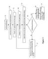
- Figure 3 depicts a first embodiment of a method of dividing and coding an image, according to the invention. This method is implemented in the coding device ( Figure 2) and includes steps E1 to E9.
- the method is implemented in the form of an algorithm which can be stored in whole or in part in any information storage means capable of cooperating with the microprocessor.
- This storage means can be read by a computer or by a microprocessor.
- This storage means is integrated or not into the device, and may be removable. For example, it may have a magnetic tape, a diskette or a CD-ROM (fixed-memory compact disc).
- the method includes the steps of:
- Step E1 is the initial partitioning of an image to be coded.
- the image is divided into rectangular tiles, with the same predetermined size.
- the width L and height H of a tile are here integer powers of two. It should be noted that other constraints on the size or shape of the tiles are possible in the context of the invention.
- the initial values of the parameters L and H are predetermined, or in a variant are calculated with respect to the image, for example with respect to the size of the image.
- an image can be divided systematically into four tiles.
- the tiles are positioned on the image in accordance with a regular structure.
- the tiles are positioned as from the top left-hand corner of the image, which then corresponds to the top left-hand corner of a tile.
- the partitioning of the image is described by the two parameters L and H, which are respectively the width and height of a tile.
- the partitioning can be described by two other parameters which represent the parameters L and H.
- the partitioning can be represented by log 2 (L) and log2(H).
- the partitioning can be effected with tiles of different shapes, or different sizes. For example, it can result from a quadtree decomposition.
- step E2 is the extraction of the representation of the partitioning effected at the previous step.
- the parameters L and H are extracted from a memory in which they are stored.
- the following step E3 is the display of a representation of the image.
- This representation is preferably the image itself, or can be a modified version of the image, for example a sub-image extracted from the original image, or a reduced version of the original image, or an enlarged version of the image.
- step E4 is the display of a representation of the partitioning, in correspondence with the displayed image. As depicted in Figure 4, the limits between tiles are depicted by lines, here dotted lines. Naturally, if a reduced version of the image is displayed, then the representation of the partitioning is reduced in an identical manner.
- step E5 is a visual check on the match of the partitioning with the content of the image.
- step E6 is a test for determining whether the current partitioning is satisfactory, according to the semantic content of the image.
- step E7 which enables the user to modify the partitioning.
- Different means can be used so that the user indicates the modifications which he desires.
- symbols SB1 and SB2 such as arrows, are superimposed on the partitioning. These symbols can be repositioned by the user, by means of the mouse or commands entered by means of the keyboard. The effect of the repositioning of the symbols SB1 and SB2 is to reposition the tile limits.
- the tile sizes can be chosen from a predetermined set of sizes. Thus, for example, the tile limits are positioned at predefined positions such that the height and width of the tiles remain integer powers of two.
- Modification of the partitioning can also be a translation of the partitioning with respect to the image. Naturally it is possible to effect these two modifications in a combined fashion, that is to say to modify the tile size and to translate the partitioning.
- Step E7 is followed by the previously described step E4.
- step E6 When the response is positive at step E6, then this step is followed by the step E8 of coding the image using the current partitioning.
- the coding includes a quantisation and entropic coding of the samples of the image.
- the coded data of the image are stored in a compressed file, in which the parameters L and H for partitioning the image are also stored at step E9.
- Figure 6 depicts a second embodiment of the invention.
- the device of figure 6 is similar to the device of Figure 2 and includes the same circuits. It also includes an additional circuit 320 for simulating the coding and decoding of the image.
- the circuit 320 is connected between the circuits 31 and 310.
- This embodiment allows to display the expected distortions along the edges of the image.
- the device instead of displaying the original image and the location of the frontiers of the blocks in the partition, the device displays the expected decoded image.
- the user can visually control that the distortions along the edges do not interfere with the important image content.
- the simulating circuit 320 simulates the encoding and decoding of the image, in order to obtain the decoded image.
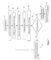
- Figure 7 depicts a second embodiment of a method according to the invention. This method is implemented in the coding device ( Figure 6).
- This embodiment includes the previously described steps E1 to E9. It also includes steps E41 and E42 between steps E4 and E5.
- Step E41 is the simulation of the encoding and decoding of the image.
- Step E42 is the display of the distortion to be expected in the image for a given image partition.
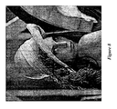
- Figure 8 represents the image together with the distortions along the edges of the image partition. This is what the user sees at step E42 in the second embodiment.
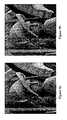
- Figures 9a and 9b depict a third embodiment of the invention. According to this embodiment, the possibility is given to the user to emphasize the distortions due to the partition of the image. This emphasis allows the user to better identify the distortions and their interaction with the image content.
- Figure 9a represents the image with its distortions
- Figure 9b represents the same image where the distortions have been artificially emphasized.
- Distortions emphasis can be achieved by a number of methods. For instance, a high pass filtering can be applied along the edges of the image. Typical examples of high-pass filtering are given in « Fundamentals of Digital Image Processing » A.K. JAIN, Prentice-Hall International Editions, 1989. Another possibility to emphasize the distortion along the edges would be to equalize the signal along the said edges. Equalization techniques are also described in the same reference.
- a fourth embodiment of a coding device 3 according to the invention is similar to the device described with reference to Figure 2. Only circuits 31 and 311 are specific to this embodiment. The other circuits will not be described.
- the signal source 30 is connected to the circuit 31 which defines at least one area of interest in the image.
- the circuit 31 is connected to an image display circuit 310.
- a representation of an area of interest is superimposed on the image display.
- the representation of the area of interest includes for example symbols which can be moved by a user by means of a mouse, for example, so as to position the areas of interest and to define their respective size.
- a single rectangular area of interest is depicted, but the number and shape of the areas may be different.
- the circuit 31 is connected to a circuit 311 for calculating the parameters for partitioning into tiles.
- a tile is a set of samples in the image, for example forming a rectangle. The tiles are adjacent. As detailed below, the partitioning into tiles depends on the areas of interest previously defined.
- the circuit 311 is connected to the circuit 32 for selecting other parameters. It should be noted that, in an equivalent manner, the circuit 32 can be arranged in front of the circuit 311.
- Figure 11 depicts a fourth embodiment of a method of dividing and coding an image, according to the invention. This method is implemented in the coding device ( Figure 10) and includes steps S1 to S3.
- the method is implemented in the form of an algorithm which can be stored in whole or in part in any information storage means capable of cooperating with the microprocessor.
- This storage means can be read by a computer or by a microprocessor.
- This storage means is integrated or not into the device, and may be removable. For example, it may have a magnetic tape, a diskette or a CD-ROM (fixed-memory compact disc).
- Step S1 is the definition of the areas of interest.
- the user is offered the possibility of defining the position, shape and size of each of the areas of interest which he chooses in the image.
- the user defines at least one area of interest by means of two symbols, here arrows, which he moves on the image in order to designate two opposite corners of a rectangle, for example by means of the mouse.
- the rectangle does indeed correspond to the area of interest, the user validates his choice, and step S1 is followed by step S2.
- Step S2 is the use of the areas of interest data previously defined by the user in order to determine tiles in the image. This step will be detailed below.
- the image is divided into rectangular tiles, with the same predetermined size.
- the width L and height H of a tile are here integer powers of two. It should be noted that other constraints on the size of the tiles are possible in the context of the invention.
- the tiles are positioned on the image in accordance with a regular structure.
- the tiles are positioned as from the top left-hand corner of the image, which then corresponds to the top left-hand corner of a tile.
- the tiles on the right and bottom edges of the image are truncated.
- Such a partitioning of the image is described by the two parameters L and H, which are respectively the width and height of a tile.
- the partitioning can be described by two other parameters which represent the parameters L and H.
- the partitioning can be represented by log 2 (L) and log 2 (H).
- the partitioning can be effected with tiles of different shapes, or different sizes. For example, it can result from a quadtree decomposition.
- Step S2 is followed by the step S3 of coding the image using the previously defined partitioning.
- the coding includes a quantisation and entropic coding of the samples of the image.
- the image coding data are stored in the compressed file, in which the image partitioning parameters are also stored.
- Step S2 depicts an embodiment of step S2 of forming the partitioning of the image as a function of the area of interest data.
- Step S2 includes sub-steps S20 to S27.
- Step S20 is the determination of a width L and height H of a tile.
- the greatest area of interest width is considered, and the width L chosen is the width which is immediately greater than it.
- the greatest area of interest height is considered, and the height H chosen is the height which is immediately greater than it.
- step S21 is a test for determining whether there exists an area of interest through which a tile limit passes. This is because the tiles are formed and positioned as from the top left-hand corner of the image, whilst the areas of interest are positioned freely on the image. Consequently it is possible that an area of interest may have a tile limit passing through it, and consequently shared between two tiles.
- step S21 is followed by step S22, at which the tile width is increased by a predetermined value.
- step S22 is followed by step S23, which is identical to step S21.
- step S23 is followed by step S24, at which the tile height is increased by a predetermined value and the tile width is returned to its previous value.
- step S24 is followed by step S25, which is identical to step S21.
- step S25 is followed by step S26, at which the tile width is once again increased by the predetermined value.
- step S26 is followed by step S21.
- this method makes it possible to form the smallest possible tiles while taking account of areas of interest, which makes it possible to keep the largest possible number of tiles in the image.
- the partitioning can also be translated with respect to the image.
- step S3 which effects the coding of the image with the partitioning obtained.
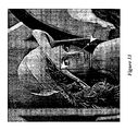
- Such a partitioning is depicted in Figure 15. The area of interest is completely included in one of the tiles of the partitioning.
Landscapes
- Engineering & Computer Science (AREA)
- Multimedia (AREA)
- Signal Processing (AREA)
- Physics & Mathematics (AREA)
- Discrete Mathematics (AREA)
- General Physics & Mathematics (AREA)
- Compression Or Coding Systems Of Tv Signals (AREA)
- Compression, Expansion, Code Conversion, And Decoders (AREA)
- Investigating Or Analysing Materials By The Use Of Chemical Reactions (AREA)
Applications Claiming Priority (4)
| Application Number | Priority Date | Filing Date | Title |
|---|---|---|---|
| FR9916016 | 1999-12-17 | ||
| FR9916021 | 1999-12-17 | ||
| FR9916021A FR2802694A1 (fr) | 1999-12-17 | 1999-12-17 | Codage de signal numerique avec formation de tuiles |
| FR9916016 | 1999-12-17 |
Publications (2)
| Publication Number | Publication Date |
|---|---|
| EP1109409A2 true EP1109409A2 (de) | 2001-06-20 |
| EP1109409A3 EP1109409A3 (de) | 2011-11-30 |
Family
ID=26235186
Family Applications (1)
| Application Number | Title | Priority Date | Filing Date |
|---|---|---|---|
| EP00403475A Withdrawn EP1109409A3 (de) | 1999-12-17 | 2000-12-11 | Digitale Signalcodierung mit fliesenartiger Unterteilung |
Country Status (3)
| Country | Link |
|---|---|
| US (2) | US7088858B2 (de) |
| EP (1) | EP1109409A3 (de) |
| JP (1) | JP4536913B2 (de) |
Cited By (1)
| Publication number | Priority date | Publication date | Assignee | Title |
|---|---|---|---|---|
| WO2017048991A1 (en) * | 2015-09-18 | 2017-03-23 | Qualcomm Incorporated | Variable partition size for block prediction mode for display stream compression (dsc) |
Families Citing this family (11)
| Publication number | Priority date | Publication date | Assignee | Title |
|---|---|---|---|---|
| EP1109409A3 (de) * | 1999-12-17 | 2011-11-30 | Canon Kabushiki Kaisha | Digitale Signalcodierung mit fliesenartiger Unterteilung |
| US20030005464A1 (en) * | 2001-05-01 | 2003-01-02 | Amicas, Inc. | System and method for repository storage of private data on a network for direct client access |
| FR2826227B1 (fr) * | 2001-06-13 | 2003-11-28 | Canon Kk | Procede et dispositif de traitement d'un signal numerique code |
| JP3883932B2 (ja) * | 2002-08-20 | 2007-02-21 | 三洋電機株式会社 | 記録媒体管理装置及びこれを用いたデジタルカメラ |
| FR2844935B1 (fr) * | 2002-09-25 | 2005-01-28 | Canon Kk | Transcodage de donnees numeriques |
| FR2889382A1 (fr) * | 2005-07-29 | 2007-02-02 | Canon Res Ct France Soc Par Ac | Procede et dispositif de filtrage d'un signal numerique multidimensionnel et procedes et dispositifs de codage et decodage associes |
| FR2906093A1 (fr) * | 2006-09-18 | 2008-03-21 | Canon Kk | Procedes et dispositifs de codage et de decodage, systeme de telecommunication et programme d'ordinateur les mettant en oeuvre |
| US8588539B2 (en) * | 2008-02-20 | 2013-11-19 | Canon Kabushiki Kaisha | Methods and devices for filtering and coding a digital signal |
| EP2105329B1 (de) * | 2008-03-26 | 2010-09-22 | Mazda Motor Corporation | Fahrzeugsaufhängungs-Hilfsrahmenstruktur |
| EP2299716B1 (de) | 2009-09-09 | 2016-11-23 | Canon Kabushiki Kaisha | Verfahren und Vorrichtung zur Codierung eines multidimensionalen digitalen Signals |
| US11677969B2 (en) * | 2019-03-22 | 2023-06-13 | Tencent America LLC | Method and apparatus for video coding |
Citations (1)
| Publication number | Priority date | Publication date | Assignee | Title |
|---|---|---|---|---|
| US5815168A (en) | 1995-06-23 | 1998-09-29 | Cirrus Logic, Inc. | Tiled memory addressing with programmable tile dimensions |
Family Cites Families (26)
| Publication number | Priority date | Publication date | Assignee | Title |
|---|---|---|---|---|
| GB8710737D0 (en) * | 1987-05-06 | 1987-06-10 | British Telecomm | Video image encoding |
| US5060285A (en) | 1989-05-19 | 1991-10-22 | Gte Laboratories Incorporated | Hierarchical variable block size address-vector quantization using inter-block correlation |
| US5241395A (en) | 1989-08-07 | 1993-08-31 | Bell Communications Research, Inc. | Adaptive transform coding using variable block size |
| JPH04213987A (ja) * | 1990-12-12 | 1992-08-05 | Sony Corp | 画像データの高能率符号化装置 |
| JPH0723423A (ja) * | 1993-06-16 | 1995-01-24 | Hitachi Ltd | ディジタル映像信号記録再生装置 |
| JPH07177508A (ja) * | 1993-12-17 | 1995-07-14 | Hitachi Denshi Ltd | 画像データ圧縮伸長装置 |
| US6005679A (en) * | 1994-08-22 | 1999-12-21 | Fuji Photo Film Co., Ltd. | Image data filing system for quickly retrieving an area of interest of an image from a reduced amount of image data |
| DE69526711T2 (de) * | 1994-11-04 | 2002-08-29 | Matsushita Electric Industrial Co., Ltd. | Bildkodierungsvorrichtung und -verfahren |
| JPH08205144A (ja) * | 1995-01-20 | 1996-08-09 | Canon Inc | 画像符号化装置 |
| JPH08317391A (ja) * | 1995-05-15 | 1996-11-29 | Sony Corp | 動画像データ圧縮装置および動画像データ伸長装置 |
| US5712995A (en) * | 1995-09-20 | 1998-01-27 | Galileo Frames, Inc. | Non-overlapping tiling apparatus and method for multiple window displays |
| KR0179166B1 (ko) * | 1995-10-04 | 1999-05-01 | 문정환 | 디지탈 영상신호처리용 메모리장치 |
| EP1120969B1 (de) * | 1996-05-17 | 2003-02-05 | Matsushita Electric Industrial Co., Ltd. | Bewegungskompensierter Videodekoder |
| KR100235064B1 (ko) * | 1996-05-23 | 1999-12-15 | 전주범 | 재배열된 블록 기반 부호화 기법을 이용하여 비디오 신호의 물체영역을 부호화하기 위한 장치 |
| JPH10178639A (ja) * | 1996-12-19 | 1998-06-30 | Matsushita Electric Ind Co Ltd | 画像コーデック部および画像データ符号化方法 |
| US7003168B1 (en) * | 1997-03-11 | 2006-02-21 | Vianet Technologies, Inc. | Image compression and decompression based on an integer wavelet transform using a lifting scheme and a correction method |
| US5949911A (en) * | 1997-05-16 | 1999-09-07 | Teralogic, Inc. | System and method for scalable coding of sparse data sets |
| US6121970A (en) * | 1997-11-26 | 2000-09-19 | Mgi Software Corporation | Method and system for HTML-driven interactive image client |
| JPH11196410A (ja) * | 1997-12-25 | 1999-07-21 | Victor Co Of Japan Ltd | 動画像符号化方法、動画像符号化装置及び動画像信号記録媒体 |
| US6501860B1 (en) * | 1998-01-19 | 2002-12-31 | Canon Kabushiki Kaisha | Digital signal coding and decoding based on subbands |
| DE69904462T2 (de) * | 1998-05-01 | 2003-10-02 | Powerquest Corp., Orem | Manipulation von partitionen virtueller und realer rechnerspeichervorrichtungen |
| US6711297B1 (en) * | 1998-07-03 | 2004-03-23 | University Of Pittsburgh - Of The Commonwealth System Of Higher Education | Methods and apparatus for dynamic transfer of image data |
| US6404444B1 (en) * | 1999-05-13 | 2002-06-11 | International Business Machines Corporation | Method and apparatus for displaying and controlling allocation of resource in a data processing system |
| US6535644B1 (en) * | 1999-07-01 | 2003-03-18 | Koninklijke Philips Electronics N.V. | Hierarchical foveation based on wavelets |
| TW445434B (en) * | 1999-08-04 | 2001-07-11 | Cyberlink Corp | System and method for automatically extracting facial features |
| EP1109409A3 (de) * | 1999-12-17 | 2011-11-30 | Canon Kabushiki Kaisha | Digitale Signalcodierung mit fliesenartiger Unterteilung |
-
2000
- 2000-12-11 EP EP00403475A patent/EP1109409A3/de not_active Withdrawn
- 2000-12-13 US US09/734,920 patent/US7088858B2/en not_active Expired - Fee Related
- 2000-12-18 JP JP2000384411A patent/JP4536913B2/ja not_active Expired - Fee Related
-
2006
- 2006-05-24 US US11/439,163 patent/US7315648B2/en not_active Expired - Fee Related
Patent Citations (1)
| Publication number | Priority date | Publication date | Assignee | Title |
|---|---|---|---|---|
| US5815168A (en) | 1995-06-23 | 1998-09-29 | Cirrus Logic, Inc. | Tiled memory addressing with programmable tile dimensions |
Non-Patent Citations (1)
| Title |
|---|
| A.K. JAIN: "Fundamentals of Digital Image Processing", 1989, PRENTICE-HALL |
Cited By (1)
| Publication number | Priority date | Publication date | Assignee | Title |
|---|---|---|---|---|
| WO2017048991A1 (en) * | 2015-09-18 | 2017-03-23 | Qualcomm Incorporated | Variable partition size for block prediction mode for display stream compression (dsc) |
Also Published As
| Publication number | Publication date |
|---|---|
| US7088858B2 (en) | 2006-08-08 |
| US20060210161A1 (en) | 2006-09-21 |
| JP4536913B2 (ja) | 2010-09-01 |
| US7315648B2 (en) | 2008-01-01 |
| EP1109409A3 (de) | 2011-11-30 |
| US20030223641A1 (en) | 2003-12-04 |
| JP2001244819A (ja) | 2001-09-07 |
Similar Documents
| Publication | Publication Date | Title |
|---|---|---|
| US6256415B1 (en) | Two row buffer image compression (TROBIC) | |
| US7965775B2 (en) | Selective chrominance decimation for digital images | |
| US8542932B2 (en) | Image processing method and image processing apparatus using different compression methods | |
| US20160198162A1 (en) | Quantization Method and Apparatus in Encoding/Decoding | |
| US7088858B2 (en) | Digital signal coding with division into tiles | |
| KR100574702B1 (ko) | 화상부호/복호방법 및 그 프로그램을 기록한 기록매체 | |
| KR100287624B1 (ko) | 화상데이타의압축,해제방법및그장치 | |
| CN109155851A (zh) | 利用画面内预测的影像编码、解码方法及装置 | |
| JP2013153508A (ja) | 高ダイナミックレンジコーデック | |
| JPH11127355A (ja) | 画像符号化装置、画像符号化方法および画像符号化プログラムを記録した記録媒体 | |
| US6563946B2 (en) | Image processing apparatus and method | |
| US7657108B2 (en) | Encoding of digital data combining a plurality of encoding modes | |
| JPWO2000002393A1 (ja) | 画像符号/復号方法及びそのプログラムを記録した記録媒体 | |
| JP3857509B2 (ja) | 画像処理装置、画像処理システム、画像符号化方法、及び記憶媒体 | |
| US20020051504A1 (en) | Decoding of digital data | |
| CN114387356B (zh) | 一种png格式的编码、解码方法及装置 | |
| EP1095519B1 (de) | Bereichsbasierte skalierbare bildkodierung | |
| JPH11308465A (ja) | カラー画像の符号化方法およびその符号化装置ならびにカラー画像の復号化方法およびその復号化装置 | |
| JP2005151207A (ja) | 画像符号化方法 | |
| KR20010023177A (ko) | 통계화된 톤의 컬러 큐브를 사용한 개인용 컴퓨터에서의비디오 프로세싱 방법 | |
| US7460720B2 (en) | Method and device for defining quality modes for a digital image signal | |
| JP2002051221A (ja) | 画像符号化装置、画像復号化装置、システム、及びその方法並びに記憶媒体 | |
| Miremadi | Lossy Image Compression | |
| JP3835411B2 (ja) | 画像圧縮装置、画像圧縮方法及び画像圧縮プログラム | |
| JP3691180B2 (ja) | 符号化装置、符号化方法 |
Legal Events
| Date | Code | Title | Description |
|---|---|---|---|
| PUAI | Public reference made under article 153(3) epc to a published international application that has entered the european phase |
Free format text: ORIGINAL CODE: 0009012 |
|
| AK | Designated contracting states |
Kind code of ref document: A2 Designated state(s): AT BE CH CY DE DK ES FI FR GB GR IE IT LI LU MC NL PT SE TR |
|
| AX | Request for extension of the european patent |
Free format text: AL;LT;LV;MK;RO;SI |
|
| PUAL | Search report despatched |
Free format text: ORIGINAL CODE: 0009013 |
|
| AK | Designated contracting states |
Kind code of ref document: A3 Designated state(s): AT BE CH CY DE DK ES FI FR GB GR IE IT LI LU MC NL PT SE TR |
|
| AX | Request for extension of the european patent |
Extension state: AL LT LV MK RO SI |
|
| RIC1 | Information provided on ipc code assigned before grant |
Ipc: H04N 7/26 20060101AFI20111021BHEP |
|
| 17P | Request for examination filed |
Effective date: 20120326 |
|
| AKX | Designation fees paid |
Designated state(s): DE FR GB |
|
| 17Q | First examination report despatched |
Effective date: 20121121 |
|
| STAA | Information on the status of an ep patent application or granted ep patent |
Free format text: STATUS: THE APPLICATION IS DEEMED TO BE WITHDRAWN |
|
| 18D | Application deemed to be withdrawn |
Effective date: 20150701 |