EP1109732B1 - Snackspender - Google Patents
Snackspender Download PDFInfo
- Publication number
- EP1109732B1 EP1109732B1 EP99935397A EP99935397A EP1109732B1 EP 1109732 B1 EP1109732 B1 EP 1109732B1 EP 99935397 A EP99935397 A EP 99935397A EP 99935397 A EP99935397 A EP 99935397A EP 1109732 B1 EP1109732 B1 EP 1109732B1
- Authority
- EP
- European Patent Office
- Prior art keywords
- door
- cam
- snack
- carousel
- slot
- Prior art date
- Legal status (The legal status is an assumption and is not a legal conclusion. Google has not performed a legal analysis and makes no representation as to the accuracy of the status listed.)
- Expired - Lifetime
Links
- 235000011888 snacks Nutrition 0.000 title claims abstract description 62
- 238000000034 method Methods 0.000 claims description 14
- 230000007246 mechanism Effects 0.000 description 27
- 230000000712 assembly Effects 0.000 description 21
- 238000000429 assembly Methods 0.000 description 21
- 230000008859 change Effects 0.000 description 11
- 230000008901 benefit Effects 0.000 description 6
- 230000008569 process Effects 0.000 description 6
- 230000003213 activating effect Effects 0.000 description 4
- 238000013519 translation Methods 0.000 description 4
- 238000013461 design Methods 0.000 description 2
- 238000004458 analytical method Methods 0.000 description 1
- 238000013459 approach Methods 0.000 description 1
- 230000015572 biosynthetic process Effects 0.000 description 1
- 230000000903 blocking effect Effects 0.000 description 1
- 238000009429 electrical wiring Methods 0.000 description 1
- 238000005516 engineering process Methods 0.000 description 1
- 238000003780 insertion Methods 0.000 description 1
- 230000037431 insertion Effects 0.000 description 1
- 230000003993 interaction Effects 0.000 description 1
- 238000004519 manufacturing process Methods 0.000 description 1
- KJFBVJALEQWJBS-XUXIUFHCSA-N maribavir Chemical compound CC(C)NC1=NC2=CC(Cl)=C(Cl)C=C2N1[C@H]1O[C@@H](CO)[C@H](O)[C@@H]1O KJFBVJALEQWJBS-XUXIUFHCSA-N 0.000 description 1
- 229920003023 plastic Polymers 0.000 description 1
- 238000012545 processing Methods 0.000 description 1
- 230000000750 progressive effect Effects 0.000 description 1
Images








Classifications
-
- G—PHYSICS
- G07—CHECKING-DEVICES
- G07F—COIN-FREED OR LIKE APPARATUS
- G07F11/00—Coin-freed apparatus for dispensing, or the like, discrete articles
- G07F11/46—Coin-freed apparatus for dispensing, or the like, discrete articles from movable storage containers or supports
- G07F11/50—Coin-freed apparatus for dispensing, or the like, discrete articles from movable storage containers or supports the storage containers or supports being rotatably mounted
- G07F11/52—Coin-freed apparatus for dispensing, or the like, discrete articles from movable storage containers or supports the storage containers or supports being rotatably mounted about horizontal axes
-
- G—PHYSICS
- G07—CHECKING-DEVICES
- G07F—COIN-FREED OR LIKE APPARATUS
- G07F11/00—Coin-freed apparatus for dispensing, or the like, discrete articles
- G07F11/46—Coin-freed apparatus for dispensing, or the like, discrete articles from movable storage containers or supports
- G07F11/50—Coin-freed apparatus for dispensing, or the like, discrete articles from movable storage containers or supports the storage containers or supports being rotatably mounted
- G07F11/54—Coin-freed apparatus for dispensing, or the like, discrete articles from movable storage containers or supports the storage containers or supports being rotatably mounted about vertical axes
-
- A—HUMAN NECESSITIES
- A21—BAKING; EDIBLE DOUGHS
- A21D—TREATMENT OF FLOUR OR DOUGH FOR BAKING, e.g. BY ADDITION OF MATERIALS; BAKING; BAKERY PRODUCTS
- A21D13/00—Finished or partly finished bakery products
- A21D13/80—Pastry not otherwise provided for elsewhere, e.g. cakes, biscuits or cookies
-
- G—PHYSICS
- G07—CHECKING-DEVICES
- G07F—COIN-FREED OR LIKE APPARATUS
- G07F11/00—Coin-freed apparatus for dispensing, or the like, discrete articles
- G07F11/62—Coin-freed apparatus for dispensing, or the like, discrete articles in which the articles are stored in compartments in fixed receptacles
Definitions
- This invention relates to snack dispensers generally. Vending dispensers or vending machine owners and lessors have ordinary skill in this art.
- the art related to this invention falls into two major categories: 1) honor system dispensers; and 2) full security vending systems.
- Honor system snack dispensers are those dispensers where the product is displayed in an uncovered and unattended manner. When a customer desires to purchase one of the snacks contained therein, he places money in a box and removes the desired item.
- the term “honor system” stems from the fact that not only is there not a check to be sure the proper amount of money was entered in the box, but also there is no way to tell that any money was entered in the box at all.
- the "honor system” dispensers are generally used in offices and other areas not generally open to the public.
- Document US5067630 discloses a vending machine where the items on sale are displayed in cylinder-shaped carousels. Refilling of the cabinets is carried out by removing and replacing these portable segments with refilled carousels.
- a vending machine is disclosed in document US1697510, accommodating a removable money pan and an upper magazine casing part which can be lifted as a whole for replenishing the magazine with packages to be vended.
- a revolving stand suitable for accommodating articles is disclosed in US931961.
- the stand consists of cylindrical double compartment sections, each of which includes a lower cylindrical section having transparent walls and vertical support strips.
- a rotable shelf is allocated between each pair of sections.
- Document US4757956 discloses a collapsable spool holder where a pair of vertically spaced apart horizontally extending walls are telescopically inner-connected and mounted to a base and are arranged to move outwardly from the base to an erect position or to collapse into the base.
- Vending companies that maintain these honor system boxes make their use economical by.having very short turnaround times for replenishment.
- the replenishment usually takes place by having a vending company employee carry in an entire new product box, with empty change box, and replace the existing box. Restocking of the depleted box and removal of the change contained therein usually takes place at a central processing facility.
- the second type related art are full security vending machines placed for use by the general public. These machines are fully secured in that there is no possibility, save extensive physical damage, that the product or the change revenues can be pillaged.
- This snack dispensing device was created to retain the advantages of the honor snack dispensing systems, but also to add the security features present in the larger, general public machines. In other words, this snack dispensing system occupies the middle ground between the honor system snack dispensers and the full security general public dispensers. This system is designed for the smaller, not generally open to the public, snack dispensing situations; however, the system is designed to gain security of the product and proceeds in a relatively inexpensive device.
- An object of this invention is to create a snack dispensing device that has the advantages of being relatively inexpensive, easy to reload, and having 96 product selections of various sizes available and visible.
- an object of this device is to accomplish the above mentioned objectives while gaining security over the honor system dispensing methods similar to the full security snack dispensing systems with less cost.
- Another object is for the vending unit to be reliable, having as few moving parts as possible, yet not requiring an external power source.
- Another object is to have the vending unit capable of quick field service, that is, replenishing the vending unit and removing the change accumulated therein, preferably in no more than two minutes.
- Another object is to have as few steps as possible for the actual purchase of articles from the unit.
- Another object is to identify and accumulate information about total sales and which sales were from individual level. From this information both profitability and inventory can be tracked.
- Another object is to have the vending unit fit on limited size counter tops and under low height cabinets above the counter tops.
- Another object is to have the hardware and system whereby during transportation of the hardware from the vending locations to a central replenishing location and back the hardware is small in volume and protected from damage.
- Another object is to have high product visibility.
- Yet another object is to have multiple levels of vending with each level capable of having a separate price independent of the other levels and in no particular price order.
- base 12 There are seven major components to the snack dispenser: base 12 , the carousel 16, back shell 20, the trays 10 , front shell 22, pin system 160 & 162 , and door lock mechanism 32.
- the snack dispenser has four circular levels. Each level is similar in many respects.
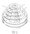
- the first level 40 has the largest radius and fourth level 46 has the smallest radius; therefore, the snack dispenser design resembles a "wedding cake".
- the material used in the prototype was a transparent plastic; however, this material may change depending upon the application desired.
- base 12 is the lowest section of the snack dispenser.
- Shaft 50 is at the center of the base 12.
- Shaft 50 is supported by mounting piece 54 on base plate 13.
- a bolt 58 through mounting piece 54 holds the shaft in place.
- the shaft 50 defines the vertical axis of the snack dispenser and enables rotation of the carousel.
- the carousel 16 and trays 10 of the snack dispenser rotate about this vertical center axis.
- Each of the detents include the circular detent wheel 70 and spring 74.
- Detent wheels 70 ride in the detent track 98 of the carousel 16.
- the detent wheel is held in place by detent guides 72; detent applicator guide 76 mounted on the plate 13 and detent wheel pin 86 on applicator 78.
- the spring is held in place by detent support 68 on the plate 13 .
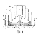
- FIGs 4 and 5 demonstrate the process by which the detent wheels 70 ride on the detent track 98 of the carousel 16. Incremental movement of the carousel is possible due to the individual sections in the detent track 98 which allow the detents to only move one single slot 158 length at a time. The customer may rotate the carousel by the use of a locking ring 102. (Figs. 3 & 4) It will be understood that the detent tract 98 shown in figure 5 is an integral portion of the carousel 16. Everything above the detent tract 98 is cut away to show the interrelationship between the detents 66 and the detent track 98.
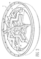
- Fig. 4 shows a cross-section of the entire invention. It will be noted that the cut for this view is not a straight line through the center. Referring to Fig. 2, the cut (upon which Fig. 4 is taken) is somewhat of a zigzag starting with a cut through the center of the left most detent 66, then proceeding toward the front of the invention. The cut then turns and cuts through the center of the left front roller 62 to the center, and then back out to the right front roller 62, then through the right most detent 66.
- the purpose of the zigzag cut of this figure is to demonstrate not only the interrelationship between the many parts indicated therein but specifically the relationship of the detent 66 to the detent track 98 and the relationship of the roller 62 with the race 96 .
- the carousel includes two identical circular center pieces, lower piece 84 and upper piece 82 .
- the carousel 16 is placed on top of the base 12.
- Shaft 50 extends through the shaft hole 48 of each of the center pieces 82 & 84 .
- the center pieces are supported by six tray supports 88.
- the tray supports 88 are attached to an inside circular band 92 on the race 96 .
- the race 96 is supported by the rollers 62 in order to allow the carousel to move smoothly.
- the back shell 20 is placed in groove 80 located along roughly two thirds of the periphery of the base.(Figs. 2, 4 and 7)
- the back shell 20 is attached by the connector lugs 104 shown in Fig. 7 in slots (not shown for clarity of drawings) in groove 80.
- the back shell supports the coin box 18 inside the coin box cavity 106 .
- the coin box 18 allows the customer to insert coins into the bank container, which are processed, and then credit information is communicated to the door lock mechanism 32 to ensure that the proper payment has been made for the desired selection.
- the specifics of the coin box are beyond the scope of this application and are not shown for simplicity.
- a tier or level is defined as a row along which the trays are located. Each tray 10 on a particular tier is of identical size proportions.
- the snack dispenser has four tiers. The four tiers are distinguishable by their diameter and the amount of money required to purchase a snack from the specific tier.
- the tiered tray assembly 108 in this embodiment comprises three segment assemblies 110. Each segment assembly spans 120 degrees of the complete circle of the tiered tray assembly 108 of the embodiment shown. It will be understood that any number of segment assemblies could be used, so long as they comprise the complete circle of the tiered tray assembly. With all the trays 10 in place on a particular level, the trays form a circular trough. The term trough indicating that a cross section of the trays would reveal squared bottoms. Circular indicating the square bottom troughs form a complete circle.
- the trough width of the top two trays 44 and 46 is greater than the trough width of the bottom two trays 40 and 42.
- each tray (42, 44 and 46) on levels 2, 3, and 4 has T-lugs 116.
- Each tray (40, 42, and 44) on level 1, 2, and 3 has T-grooves or T-slots 118.
- the process of collapsing and expanding the trays is an interrelationship between the T-lugs and T-grooves.
- T-lug 116 of one tray is placed first in T-groove 118 of a next larger diameter tray.
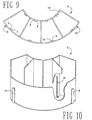
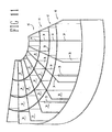
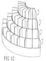
- the T-lug 116 is then extended to the top of the T-groove of the larger tray. This process is repeated for each individual tray until all four levels have been connected to form a segment assembly 110 which resembles Fig. 11 when collapsed, and Fig. 12 when telescoped.
- the segment assemblies 110 telescoped and placed on the carousel form the "wedding cake" formation shown in Fig. 1 and 4.
- the front shell 22 is placed on the snack dispenser.
- the front shell 22 and the back shell 20 mesh and lock to secure the snack vendor.
- Each horizontal surface of the back shell 20 has grooves or slots on the edges closest to the front cover and away from the door lock mechanism 32.
- the front shell 22 has complimentary protrusions that fit into the grooves or slots of the back shell 20.
- locking the front and back shells to secure the snack vendor is accomplished by placing the front shell 22 slightly overlapping the back shell 20 on the side opposite the door lock mechanism 32.
- the front shell 22 is rotated clockwise such that the protrusions on the front shell 22 complimentary to the grooves or slots on the back shell 20 lock into place. Further, this clockwise rotation moves a portion of the front shell 22 on the door lock mechanism 32 side to be under a portion of the door lock mechanism. This portion of the door lock mechanism is locked in place at this location by any of a number of various locking techniques.
- the front shell has four door holes 130, 132, 134, and 136. (Fig. 13) Each door hole has one door cutaway 138, to allow the door to snap into the door slots and be easily removed, two upper door guides 146 and two lower door guides 148 .
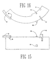
- a door is illustrated in Fig. 14, 15, and 16. It will be understood that the drawing figures are representative of all four doors 24, 26, 28 and 30 (Fig. 1). Each door will have a different radius of curvature and length, and there are two different widths, but they will all be proportionally the same. Each door has a handle 142 which is used for sliding the door in the lateral arc. The following embodiments regarding a method and devices for securing sale articles in slots are not claimed with this application.
- the guides 146 and 148 are used to ensure that the door will not get out of alignment or be difficult to open. Guides 146 slide along edge 144. (Fig. 13) Guides 148 slide along edge 154.
- Door vane 150 is used to guarantee that the door can only open to the maximum length of a slot. For instance, if the snack selected is in a double size slot 156 , the door vane 150 will hit against the back shell 20.
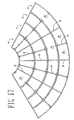
- Each individual tray is further divided into individual slots 156 and 158 as shown in Fig. 17.
- the slots are defined by both permanent 36 and removable dividers 34.
- the removable dividers are inserted or removed to allow for either single slot 158 or double slot 156 sized compartments.
- the removable dividers 34 are held in place by divider guides 35 .
- the perspective view of figure 11 shows some of the divider guides 35 , but not all of them are shown for simplicity of the drawing. It will also be noted that although in this embodiment of the invention each slot is capable of division into two slots by placement of the removable divider 34 , it is not necessary that each and every full size slot be divisible.
- the snack dispenser uses a pin mechanism to control the doors.
- Each door has two pins which control the door.
- Pin #1 160 as seen in Fig. 1, is used to allow the door to only open to the length of a single slot if the snack selected by the customer is in a single slot 158.
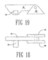
- Fig. 18 through 21 shows a schematic of the pin system. Fig. 21 depicts the process by which pin #1 160 will be used to stop the door if there is a single slot 158 space. As seen in Fig. 20, lever 164 and block 170 of the pin #1 160 are angled downward because there is not a removable divider 34 present in that position.
- Pin #2 162 shown in Fig. 1 is used to ensure that the carousel is properly aligned. If the dividers are aligned so that the customer has access to a snack (whether that snack is in a single or double size slot), pin #2 162 will rise and allow the door to open. However, if the pin is not aligned properly with a divider, a block similar to block 170 of pin #1 will fall into slot 171 on the doors and ensure that the door cannot open. The process by which pin #2 162 works is the same as the process described above for pin #1 160. Although not shown for clarity, each of pin #1 160 and pin #2 162 is covered such that no tampering with the levers of each six system can occur which would thereby bypass their functions.
- the levers 164 are pivoted to pin bases 168 mounted on front shell 22.
- the lever of pin #2 162 are mounted in reverse or mirror image to pin #1 160.
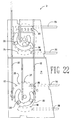
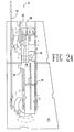
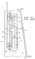
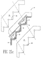
- Doors are controlled by the door lock mechanism 32 (Figs. 22 - 25).
- the door mechanism is located on the side of backshell 20. Although shown on Fig. 1 it is not shown on Fig. 7 for clarity.
- the mechanism 32 is covered by cover 33, partially on the front shell 22.
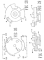
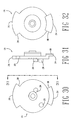
- the door lock mechanism comprises lower cam 172, upper cam 174, (Figs. 26 - 32) and three different arms 176, 178, and 180. (Fig. 33 - 39).
- the door lock mechanism 32 serves the following functions: 1) it holds all doors closed until the proper amount of money has been entered; 2) unlocks individual level doors upon receiving the correct amount of change; 3) locks the carousel in position when any door is open to eliminate the possibility of a person emptying an entire row of snacks after opening a door; 4) once any door is open, the mechanism keeps the remaining doors from opening; and 5) resets the change counter after a door is opened.
- the cam 172 and 174 are mounted for rotation on stubs on board 29.
- the board is attached to the back shell 20.
- the upper cam 174 interlocks the doors for the fourth level 46 and the third level 44 .
- the lower cam 172 interlocks the doors for the first level 40 and the second level 42.
- the interlocking feature among these two groups operate substantially the same.
- the door contacts its appropriate cam and rotates that cam. This cam rotation moves a portion of the cam to block the opening of the second door in the group. More specifically then, referring to Fig. 26 there will be seen the lower cam 172. Further, the figure shows the contact point 194 for door one and the contact point 196 for door two. Vane 150 of a level's respective door is what actually contacts the contact points.
- lower cam 172 is rotated by the door pushing at location 194.
- This rotation of the lower cam 172 rotates the door 2 block 212 such that the level 2 door cannot be opened.
- opening the second level door 28 rotates the lower cam 172 in a counter-clockwise direction.
- This counter-clockwise rotation moves the door 1 block 210 such that door 1 may not be opened.
- the same description applies to the interlocking mechanism of the upper cam 174 in relation to the level 3 and level 4 door, 26 and 24 respectively.
- vane 150 of a door only rotates its respective cam less than 90 degrees before slipping past the cam yet still holding it in the rotated position. The slipping of the vane 150 past the contact point is most prevalent when opening a door over a double slot, but could be present to some degree even when opening a door over a single slot.
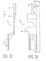
- the upper and lower cams not only interlock doors 3 and 4 and doors 1 and 2 respectively, they further interlock with each other to allow only one door to open at any one time. Interlocking between the cams is accomplished by the cam interlock arm 178 shown in Figs. 33 and 34.
- the cam interlock arm 178 connects to the upper cam 174 via a shaft and slot mechanism; specifically, shaft 204 on the upper cam 174 slides into slot 206 on the cam interlock arm 178.
- Rotation of the upper cam 174 translates the cam interlock arm 178 up and down.
- Counter-clockwise rotation of the upper cam 174 moves the cam interlock arm 178 up as shown in figure 33. This counter-clockwise rotation is caused by opening the door on the fourth level.
- Clockwise rotation of the upper cam 174 causes the cam interlock arm 178 to move down. Clockwise rotation of the upper cam 174 is caused by opening the door on the third level. It will be understood then that any rotation of the upper cam 174 causes a corresponding translation in the cam interlock arm 178.
- the cam interlock arm 178 interacts with the lower cam 172 via a ridge and groove function. More specifically, the interlock arm groove 218 interacts with the ridge 220 on the lower cam 172. With all the doors in the at-rest position, i.e. all the doors closed, the ridge 220 aligns with the interlock arm groove 218 such that the lower cam 172 is free to move rotationally. Further, in the at-rest position, the upper cam 174 is free to rotationally move because the cam interlock arm groove 218 is aligned with the ridge slot 222 of the lower cam 172.
- the cam interlock arm 178 serves another function; namely, it further acts as a price level release by operation of the price lock portion 224 .
- the price lock portion 224 consists of a downward block 226 and an upward block 228. Using these blocks, the coin counting mechanism (not described here) releases individual levels as money is added to the system. If the cam interlock arm 178 is blocked from movement in either the upward or downward direction, this effectively blocks opening of the level 3 door 26 and level 4 door 24 respectively.
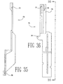
- Figs. 35 and 36 show the lower cam price block arm 176.
- the lower cam price block arm 176 serves two functions: 1) to block the lower level doors from being open before an appropriate amount of money has been entered; and 2) to operate the carousel stop arm 180.
- the lower cam price block arm 176 accomplishes price level locks via the price lock portion 230.
- the price lock arm 230 consists of a downward block 232 and an upward block 234. If the lower cam price block arm 176 cannot move because of a impediment in either the downward block 232 or the upward block 234 location, this effectively stops the lower cam 172 from rotating. This rotational block keeps the lower doors from operating by blocking them against the contact points 194 and 196.
- the lower cam price block arm interacts with the lower cam by operation of shaft slot 208 with shaft 202 of the lower cam.
- the carousel stop arm 180 serves three functions: 1) to lock the carousel in place such that it may not be rotated while any door is open; 2) to reset the change counter; and 3) identify from which level a snack has been purchased.
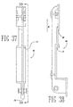
- the carousel stop arm 180 translates in the upward direction with the opening of the door as indicated in Fig. 38.
- the carousel stop arm 180 is forced upward by operation of shaft 236 on the upper cam 174 in groove 248 on the carousel stop arm 180.
- the shaft 236 is positioned in groove 248 such that it only contacts the upper portion of groove 248 during clockwise rotation of the upper cam 174 .
- the shaft 236 does not contact any sidewalls of groove 248.
- Upward translation of the carousel stop arm 180 during counter-clockwise rotation of the upper cam 174 is accomplished by operation of the push bar 238 on the cam interlock arm 178 pushing at push location 177 as shown in Figs. 37 and 38.
- the carousel stop arm 180 is forced upward with each movement of the lower cam 172 .
- shaft 240 interacts with the carousel stop arm at location 179 to force it upward.
- the push bar 242 on the lower cam 172 price block arm 176 operates to force the carousel stop arm 180 in the upward direction by pushing on the carousel stop arm 180 at location 177 .
- the carousel stop arm 180 It is this upward movement of the carousel stop arm 180 that resets the change counter upon the opening of a door on any level.
- the carousel stop arm could equally be called a clear credit arm.
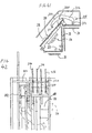
- FIGs. 41 and 42 which show that when an activating force through an element 318 moves against arm 316 of lever 310 that the lever 310 will pivot about pivot shaft 320 compressing spring 314 .
- This pivoting motion will withdraw pin 312 from one of the notches selected from notches 226, 228, 232 and 234 .
- the withdrawal of the pin 312 permits the door to open to dispense a snack.
- a coin controller in the coin box 18 has the mechanism to provide the activating force to move a selected element 318 .
- the selected element is on the basis of the value of coins deposited.
- Coin controllers to select the activating force are known. See for example STONER et al, U.S. Patent 2,934,192.
- the carousel stop arm 180 locks carousel rotation with each upward movement.
- the carousel lock arm is one in a series of members that locks the carousel in place responsive to opening of a door on the vending unit.
- the carousel lock arm translates upward upon the opening of any door. This upward translation locks rotation of the carousel by rocking rocker 244 which translates up lock member 246 .
- Lock member 246 when translated upward, locks rotation of the carousel by sliding a pin or shaft in the holes of the locking ring 102.
- Guide rails 182 on board 29 guide the arms 176, 178, and 180.
- the board is attached to front cover support 33f at the front and to back cover support 33b at the back.
- these supports are identical in size and shape too and rest upon the front cover 27.
- the front cover 27 does not provide the support of elements 33f and 33b .
- the cover clips 205 on the covers 33f and 33b will match the front and back shell clips 201 and 203.
- the cover 33 will fit with the covers 33f and 33b.
- a unique characteristic of the tray system is that the segment assemblies 110 expand telescopically to form a "wedding cake” design, but also can collapse into a flat conformation, whereby each tray is of near identical height.
- the primary advantage of this tray system is that the snack replenisher (i.e. the person who will maintain the snack dispenser) can efficiently and quickly exchange the deplenished segment assemblies with replenished segment assemblies by simply removing the deplenished ones from the snack dispenser, collapsing them, and replacing the deplenished segment assemblies with replenished ones.
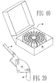
- replenishing the snack dispenser as described by this invention comprises the following steps: 1) removing the front shell 22 (thus opening the snack dispenser); 2) revolve the carousel so one segment assembly 110 is at the open gap of the back shell 20 ; 3) remove the deplenished segment assembly from the snack dispenser; 4) collapse the deplenished segment assembly and place it in a box 109; (Fig. 40) 5) telescope a replenished segment assembly; 6) place the telescoped segment assembly in the snack dispenser; 7) repeat steps three to six until all the deplenished segment assemblies have been replaced; 9) exchange the full change receptacle with a replenished change receptacle; and 10) place and lock the front shell back 22 on the snack dispenser.
- the box 109 shown in Fig. 40 is somewhat of a specialty item.
- the internal dimensions of the box need to be great enough to allow the insertion of the collapsed segment assemblies 110.
- the segment assemblies 110 should be placed in the box to form a circle.
- a full coin box 18 from a replenished snack vending machine will be placed in the center of the box in the hole created in the center of the segment assemblies 110. So that only one box would be required to be carried in to replenish a snack vendor, the lid of the box should be sized to hold the same elements as just described when open. In that regard, a person replenishing a snack vendor would open the box cover and fold it around to be substantially on the same plane as that portion of the box holding the replenished segment assemblies 110 and empty coin box.
- the boxed collapsed segment assemblies can be easily stacked on top of the other boxed segment assemblies and returned to the snack distributor to be replenished with new snacks.
- a battery powered electronic device within the coin box 18 can readily determine and accumulate the value of the coins which are deposited in the box. Also the electronic device can readily read an identification indicia located on the top of the shaft 50 upon which the coin box 18 rests. Thus personell at the replenishing area can verify the actual money in the coin box with the total value which has been accumulated from the coins. Likewise, the electronic device can record the number of movements of the respective arms that are moved with the opening of the doors. In this way the replenishing center personell can correlate the number of snacks on each level and price level which have been vended with the physical number left in the replenished tray. With this information, the overpay can be easily calculated as well as the price variety of snacks that are being vended at each of the locations according to the data obtained.
- Purchasing a snack from the vending unit will then comprise the following steps: 1) A potential customer would approach the vending unit and survey the snacks contained under the transparent front shell by turning the carousel with that portion of the exposed lock ring; 2) The potential customer would then position the desired item underneath the door; 3) The customer would then place money in the coin box where said money will be summed (coin box internals not described in this application); 4) As money is added to the coin box, individual level doors are released when the sum of the money entered is equal to or greater than the money required to open a door on that particular tier; 5) The customer opens the door above the item desired; 6) The customer removes the desired item from the slot; and 7) The customer releases the door whereupon the spring associated with a lock member returns parts to an opening position. All the doors are again locked closed until the cycle can be repeated.
Landscapes
- Physics & Mathematics (AREA)
- General Physics & Mathematics (AREA)
- Life Sciences & Earth Sciences (AREA)
- Engineering & Computer Science (AREA)
- Food Science & Technology (AREA)
- Vending Machines For Individual Products (AREA)
- Control Of Vending Devices And Auxiliary Devices For Vending Devices (AREA)
- Warehouses Or Storage Devices (AREA)
- Confectionery (AREA)
- Medicines Containing Plant Substances (AREA)
Claims (3)
- Verfahren zum Nachfüllen einer Imbissverkaufsvorrichtung (12,16,70,110) mit Artikeln, mit folgenden Schritten:a) Aufsperren einer Abdeckung (70) über der geleerten, mehrstöckigen Behälteranordnung (108),b) Entfernen der Abdeckung (70), dannc) Entfernen der geleerten, mehrstöckigen Behälteranordnung (108) aus der Imbissverkaufsvorrichtung,d) Zusammenfalten der geleerten Behälteranordnung (108) zu einer Anordnung mit im Wesentlichen einheitlicher Höhe,e) Beschaffen einer nachgefüllten, zusammen gefalteten, mehrstöckigen Behälteranordnung und eines leeren Münzbehälters (18),f) Auseinanderfalten einer nachgefüllten Behälteranordnung aus der Anordnung einheitlicher Höhe zu einer mehrstöckigen Anordnung (108),g) Anordnen der nachgefüllten, mehrstöckigen Behälteranordnung in der Imbissverkaufsvorrichtung,h) Austauschen eines Münzbehälters (18) in der Verkaufsvorrichtung mit dem leeren Münzbehälter (18)i) Anordnen der entfernten Komponenten in dem Behälter,j) Anordnen der Abdeckung (70) undk) Abschließen der Abdeckung.
- Verfahren zum Ausstellen von Artikeln zum Verkauf in einer Imbissverkaufsvorrichtung (12,16,70,110) umfassend:gekennzeichnet durch die folgenden Schritte:a) Anordnen von einigen Artikeln in Schlitzen (156, 158), welche durch Segmentieren (34,36) einer unteren, transparenten, ringförmigen Wanne (110) ausgebildet sind,b) Anordnen einiger Artikel in den Schlitzen (156, 158), welche durch Segmentieren einer oberen, transparenten, ringförmigen Wanne (110) ausgebildet sind, deren Außendurchmesser etwas kleiner ist als der Innendurchmesser der unteren, ringförmigen Wanne (110),c) Anordnen der oberen Wanne innerhalb der unteren Wanne (110),d) Abstufen der Höhe der oberen und unteren Wanne derart, dass die Oberseite der oberen Wanne eine größere Höhe aufweist als die Oberseite der unteren Wanne, hierdurche) Ausbilden eines mehrstöckigen Stapels (108)f) Drehen des mehrstöckigen Stapels (108) zum Ansehen, dannd) Stoppen des mehrstöckigen Stapels in einer Position, bei der ein Schlitz, welcher einen gewählten Artikel enthält, in einer vorbestimmten Position ausgerichtet ist, dannh) Entfernen eines gewählten Artikels aus dem Schlitz (56,58).
- Verfahren nach Anspruch 2, wobei im Schritt e) der mehrstöckige Stapel (108) durch wenigstens vier Wannen gebildet ist.
Applications Claiming Priority (3)
| Application Number | Priority Date | Filing Date | Title |
|---|---|---|---|
| US111333 | 1998-07-07 | ||
| US09/111,333 US6234346B1 (en) | 1997-07-11 | 1998-07-07 | Snack dispenser |
| PCT/US1999/014989 WO2000001603A1 (en) | 1998-07-07 | 1999-07-02 | Snack dispenser |
Publications (3)
| Publication Number | Publication Date |
|---|---|
| EP1109732A1 EP1109732A1 (de) | 2001-06-27 |
| EP1109732A4 EP1109732A4 (de) | 2002-10-30 |
| EP1109732B1 true EP1109732B1 (de) | 2004-03-03 |
Family
ID=22337899
Family Applications (1)
| Application Number | Title | Priority Date | Filing Date |
|---|---|---|---|
| EP99935397A Expired - Lifetime EP1109732B1 (de) | 1998-07-07 | 1999-07-02 | Snackspender |
Country Status (10)
| Country | Link |
|---|---|
| US (3) | US6234346B1 (de) |
| EP (1) | EP1109732B1 (de) |
| JP (1) | JP4494635B2 (de) |
| KR (1) | KR100641764B1 (de) |
| AT (1) | ATE260854T1 (de) |
| AU (2) | AU757625B2 (de) |
| CA (1) | CA2336638C (de) |
| DE (1) | DE69915311T2 (de) |
| MX (1) | MXPA01000861A (de) |
| WO (1) | WO2000001603A1 (de) |
Families Citing this family (36)
| Publication number | Priority date | Publication date | Assignee | Title |
|---|---|---|---|---|
| US20040079616A1 (en) * | 1997-07-11 | 2004-04-29 | Castleberry Billy J. | Snack dispenser |
| US6234346B1 (en) * | 1997-07-11 | 2001-05-22 | Newco Enterprises, Inc. | Snack dispenser |
| USD475413S1 (en) | 1998-07-07 | 2003-06-03 | Newco Enterprises, Inc. | Snack dispenser |
| US20040245278A1 (en) * | 2003-01-30 | 2004-12-09 | Steffens Lowell G. | Propane tank vending machine |
| US20070170201A1 (en) * | 2003-01-30 | 2007-07-26 | Steffens Lowell G | Propane tank vending machine assembly |
| TWI240920B (en) * | 2003-03-21 | 2005-10-01 | Mediatek Inc | Method for accessing variable memory of an optical disk drive |
| US7320415B2 (en) * | 2003-05-02 | 2008-01-22 | Robbins Industries, Inc. | Condiment dispensing container and carousel |
| CA2430936A1 (en) * | 2003-06-10 | 2004-12-10 | Wellesley Alexander Allen | Manually operated pill dispenser |
| US20050060063A1 (en) * | 2003-09-11 | 2005-03-17 | Genesearch Pty Ltd. | Automated item dispensing systems |
| USD545373S1 (en) | 2004-01-30 | 2007-06-26 | Avalon Returnable Packaging, Inc | Propane tank vending machine assembly |
| US20050199642A1 (en) * | 2004-03-15 | 2005-09-15 | Maddock Cindie L. | Programmable snack dispenser and method |
| USD552881S1 (en) * | 2004-05-26 | 2007-10-16 | Nobel Biocare Services Ag | Rack |
| US7395945B2 (en) * | 2004-09-24 | 2008-07-08 | Nexiant | Controlled dispensing system with modular carousel |
| KR100654719B1 (ko) * | 2005-05-19 | 2006-12-08 | 주식회사 모리스 | 가변 계단식 필기구 진열대 |
| GB0606923D0 (en) * | 2006-04-06 | 2006-05-17 | Allen Wellesley A | Manually operated pill dispenser |
| US7185605B1 (en) * | 2006-07-03 | 2007-03-06 | Lush Raymon W | Multi-tier collapsible feeder |
| WO2008025101A1 (en) * | 2006-08-31 | 2008-03-06 | Addco Nominees Pty Ltd | Improved dispenser assembly |
| PT1927308E (pt) * | 2006-11-28 | 2010-05-26 | Hans Georg Hagleitner | Moente de apoio |
| US20090071971A1 (en) * | 2007-04-25 | 2009-03-19 | Grafton Canada Limited | Secure medication dispensation mechanism |
| USD581699S1 (en) | 2007-06-13 | 2008-12-02 | Terrence Harrison | Storage device for boxed and bottled goods |
| US7635066B2 (en) * | 2007-10-09 | 2009-12-22 | Harrison Terrence M | Revolving storage device |
| USD617146S1 (en) | 2008-12-12 | 2010-06-08 | Harrison Terrence | Storage device for boxed and bottled goods |
| SE0950316A1 (sv) * | 2009-05-06 | 2010-04-27 | Assa Ab | Myntlås |
| US8469228B2 (en) * | 2011-03-24 | 2013-06-25 | Sleegers Engineered Products, Inc. | Self-serve kiosk with rotatable container carousel |
| TW201439994A (zh) * | 2012-12-28 | 2014-10-16 | Hon Hai Prec Ind Co Ltd | 貨物支撐裝置 |
| US9345344B1 (en) * | 2015-01-06 | 2016-05-24 | Samira Arabi-Beam | Transportable display holder for articles stored therein |
| USD792122S1 (en) | 2015-03-31 | 2017-07-18 | Hans Georg Hagleitner | Paper roll holder |
| USD835922S1 (en) | 2015-03-31 | 2018-12-18 | Hans Georg Hagleitner | End piece for a paper roll holder |
| USD835921S1 (en) | 2015-03-31 | 2018-12-18 | Hans Georg Hagleitner | End piece for a paper roll holder |
| USD836941S1 (en) | 2015-03-31 | 2019-01-01 | Hans Georg Hagleitner | End piece for a paper roll holder |
| USD765183S1 (en) * | 2015-11-20 | 2016-08-30 | Robert Lowery | Marble game |
| USD813952S1 (en) * | 2016-05-05 | 2018-03-27 | Scott Siepmann | Convertible tiered game system |
| USD813951S1 (en) * | 2016-05-05 | 2018-03-27 | Scott Siepmann | Tiered beverage pong game system |
| USD849460S1 (en) * | 2016-07-21 | 2019-05-28 | Soremartec S.A. | Display stand |
| KR200492860Y1 (ko) * | 2019-02-21 | 2020-12-24 | 비알코리아주식회사 | 케이크 장식품 |
| USD940476S1 (en) * | 2019-06-26 | 2022-01-11 | Hagleitner Hygiene International Gmbh | Holder for rolls of paper |
Family Cites Families (65)
| Publication number | Priority date | Publication date | Assignee | Title |
|---|---|---|---|---|
| US1140524A (en) * | 1915-05-25 | Mosler Safe Co | Safe construction. | |
| US2171492A (en) | 1939-08-29 | Coin collecting and object distrib | ||
| US164167A (en) * | 1875-06-08 | Improvement in permutation-locks for safe-doors | ||
| US1001221A (en) * | 1907-08-30 | 1911-08-22 | Edward S Pillard | Doors for safes and vaults. |
| US931961A (en) * | 1908-12-28 | 1909-08-24 | Frank N Robinson | Revolving stand. |
| US1008125A (en) * | 1911-07-29 | 1911-11-07 | Walter Eichelkraut | Safety device for cash-desks. |
| US1234022A (en) * | 1915-09-22 | 1917-07-17 | Harry W Heller | Burglar-proof safe or vault. |
| FR534590A (fr) * | 1921-04-25 | 1922-03-29 | Perfectionnements aux bougies d'allumage | |
| US1697510A (en) * | 1927-05-14 | 1929-01-01 | Doehler Die Casting Co | Vending machine |
| US1796133A (en) * | 1928-01-09 | 1931-03-10 | Polar Vend Corp | Distributing device |
| US1815281A (en) * | 1930-02-24 | 1931-07-21 | William J H Ruschmeyer | Bank vault safe |
| US2215642A (en) * | 1938-11-29 | 1940-09-24 | Rowe Mfg Co Inc | Coin operated vending machine |
| US2253554A (en) * | 1939-05-11 | 1941-08-26 | Gen Vender Mfg Company | Vending apparatus |
| US2512183A (en) * | 1945-09-11 | 1950-06-20 | Cleveland Detroit Corp | Vending machine |
| US2690144A (en) * | 1952-08-15 | 1954-09-28 | Harvey W Ellis | Safe locking mechanism |
| US3055319A (en) * | 1958-10-14 | 1962-09-25 | Asprion Anna Maria | Safety window for counters |
| GB882527A (en) * | 1958-11-28 | 1961-11-15 | John Westaway | Improvements in or relating to storage structures |
| US3163275A (en) | 1961-12-26 | 1964-12-29 | Vendo Co | Coin actuated merchandising apparatus |
| GB986019A (en) * | 1962-09-21 | 1965-03-17 | R & R Res Ltd | Subscription entertainment systems |
| US3221862A (en) * | 1963-04-29 | 1965-12-07 | Service Distributors Inc | Coin metering apparatus for multiple machine installations |
| US3305129A (en) * | 1965-03-30 | 1967-02-21 | Ideal Venders | Release mechanism for slope shelf vender, including a lock-out assembly |
| US3372784A (en) | 1965-12-02 | 1968-03-12 | Ross | Minnow vending method and machine |
| US3319821A (en) * | 1966-02-07 | 1967-05-16 | Seeburg Corp | Plural source article dispenser with separate discharge means for each source |
| US3355065A (en) * | 1966-08-03 | 1967-11-28 | James A Moe | Dispensing apparatus |
| US3664476A (en) * | 1970-03-30 | 1972-05-23 | Transvac Electronics Corp | Vending machine |
| DE2037580A1 (de) | 1970-07-29 | 1972-02-03 | J. Hengstler Kg, 7207 Aldingen | Einrichtung zum Steuern eines selbstbedienbaren Warenausgabegerätes vermittels Identifikationsdatenträgern |
| US3752287A (en) | 1971-06-10 | 1973-08-14 | Polyvend | Price selection vending machine arrangement |
| US3923327A (en) * | 1971-07-26 | 1975-12-02 | Youngstown Steel Door Co | Sealing cam interlock |
| US3797626A (en) * | 1973-01-02 | 1974-03-19 | Fawn Eng Co | Credit register mechanism |
| US3828903A (en) | 1973-02-12 | 1974-08-13 | H R Electronics Co | Vend control with escrow until available product selection |
| US3848718A (en) | 1973-11-12 | 1974-11-19 | Rock Ola Mfg Corp | Vending machine control circuit |
| US3957173A (en) * | 1974-06-26 | 1976-05-18 | Ncr Corporation | User access compartment for an automated teller machine |
| US3929257A (en) * | 1975-01-30 | 1975-12-30 | William F Shepherd Inc | Mechanical interlock device for a vending machine |
| US4037701A (en) * | 1975-09-26 | 1977-07-26 | Karl Knickerbocker | Price setter for totalizer coin mechanism |
| US4000800A (en) * | 1975-10-09 | 1977-01-04 | William F. Shepherd, Inc. | Electromechanical interlock device for a vending machine |
| DE2646985C3 (de) * | 1975-10-24 | 1978-12-14 | Glory Kogyo K.K., Himeji, Hyogo (Japan) | Steuersystem für ein MünzschlieBfach |
| JPS5269399A (en) | 1975-12-05 | 1977-06-09 | Nippon Koinko Kk | Controlling method for automatic vending machine |
| US4033442A (en) * | 1976-04-30 | 1977-07-05 | Fawn Engineering Co. | Locking and releasing mechanism for a vending machine |
| US4280181A (en) | 1976-05-20 | 1981-07-21 | H. R. Electronics Company | Cash accountability control circuit for vending and like machines |
| US4232798A (en) * | 1978-03-29 | 1980-11-11 | The Kroger Company | Automatic vending machine for delivering containers having edible product therein |
| US4201283A (en) * | 1978-05-31 | 1980-05-06 | E. B. Metal Rubber Industries, Inc. | Pilferage protection for satellite vending machine having dual pricing capability |
| US4301909A (en) | 1979-07-25 | 1981-11-24 | Snavely John D | Vending apparatus |
| US4317604A (en) * | 1980-05-05 | 1982-03-02 | Merrill Krakauer | All-purpose merchandiser |
| DE3040089A1 (de) * | 1980-10-24 | 1982-06-03 | Sielaff Gmbh & Co Automatenbau Herrieden, 8801 Herrieden | Fallklappenschacht fuer selbstverkaeufer |
| US4408546A (en) * | 1981-01-12 | 1983-10-11 | Schmidt Jacob D | Hingeless safe door assembly |
| US4391388A (en) * | 1981-04-30 | 1983-07-05 | Merrill Krakauer | Control system for increasing the versatility of an all purpose merchandiser |
| US4534474A (en) * | 1982-09-30 | 1985-08-13 | Concord Tool And Machine Company | Collapsible kitchen utensil holder |
| US4461377A (en) * | 1983-01-26 | 1984-07-24 | Crooks Randall D | Coin operated vending stack |
| US4747478A (en) * | 1983-04-29 | 1988-05-31 | Evelyn Friedman | Coin sorter and totalizer |
| US4643107A (en) * | 1985-02-11 | 1987-02-17 | Bellsouth Corporation | Security vault |
| BE904766R (fr) * | 1985-09-12 | 1986-09-01 | Staar Sa | Appareil pour la reproduction et/ou l'enregistrement successif et/ou selectif de supports d'informations. |
| US4630624A (en) * | 1986-01-22 | 1986-12-23 | Turner James R | Coin escrow apparatus for coin operated equipment |
| FR2609341B1 (fr) * | 1987-01-06 | 1989-03-03 | Cga Hbs | Distributeur automatique a rendu de monnaie |
| US4757956A (en) * | 1987-05-26 | 1988-07-19 | Mcguire Ruth F | Collapsible spool holder |
| US4942954A (en) * | 1987-08-20 | 1990-07-24 | G. T. Norton, Inc. | Vending machine |
| US5067630A (en) * | 1987-08-20 | 1991-11-26 | G. T. Norton, Inc. | Vending machine |
| US5099975A (en) * | 1988-05-27 | 1992-03-31 | Kaspar Wire Works, Inc. | Dollar slot for coin control mechanism for use with a periodical dispensing device |
| US5360093A (en) * | 1992-06-05 | 1994-11-01 | Kaspar Wire Works, Inc. | Method and apparatus for the control of a multiple of door accessible newspaper vending cabinets with a single vend control mechanism operating remote door latches |
| US5310035A (en) * | 1992-09-23 | 1994-05-10 | Revenco Corporation | Paper and coin currency totalizer for an existing vending machine |
| US5335986A (en) * | 1993-01-08 | 1994-08-09 | Metalworks, Inc. | Interlock assembly |
| US5337920A (en) * | 1993-04-21 | 1994-08-16 | Clausen Mark K | Rotatable platter storage and retrieval system |
| US5385266A (en) * | 1993-11-30 | 1995-01-31 | Pate; Ronald | Anti-theft device for coin operated newspaper dispenser |
| US5533645A (en) * | 1994-11-01 | 1996-07-09 | Fawn Engineering Corporation | Split door for vending machine |
| US6234346B1 (en) | 1997-07-11 | 2001-05-22 | Newco Enterprises, Inc. | Snack dispenser |
| US6123223A (en) * | 1998-12-21 | 2000-09-26 | Watkins; Kenneth M. | Automated vending system for floral arrangements |
-
1998
- 1998-07-07 US US09/111,333 patent/US6234346B1/en not_active Expired - Lifetime
-
1999
- 1999-07-02 MX MXPA01000861A patent/MXPA01000861A/es not_active IP Right Cessation
- 1999-07-02 KR KR1020017000194A patent/KR100641764B1/ko not_active Expired - Fee Related
- 1999-07-02 DE DE69915311T patent/DE69915311T2/de not_active Expired - Fee Related
- 1999-07-02 CA CA002336638A patent/CA2336638C/en not_active Expired - Fee Related
- 1999-07-02 WO PCT/US1999/014989 patent/WO2000001603A1/en not_active Ceased
- 1999-07-02 EP EP99935397A patent/EP1109732B1/de not_active Expired - Lifetime
- 1999-07-02 JP JP2000558016A patent/JP4494635B2/ja not_active Expired - Fee Related
- 1999-07-02 AU AU50881/99A patent/AU757625B2/en not_active Ceased
- 1999-07-02 AT AT99935397T patent/ATE260854T1/de not_active IP Right Cessation
-
2000
- 2000-11-29 US US09/725,772 patent/US6467603B2/en not_active Expired - Fee Related
-
2002
- 2002-10-21 US US10/274,732 patent/US6742674B2/en not_active Expired - Lifetime
-
2003
- 2003-05-27 AU AU2003204400A patent/AU2003204400B2/en not_active Ceased
Also Published As
| Publication number | Publication date |
|---|---|
| CA2336638C (en) | 2009-09-01 |
| AU5088199A (en) | 2000-01-24 |
| ATE260854T1 (de) | 2004-03-15 |
| US20030071052A1 (en) | 2003-04-17 |
| US6467603B2 (en) | 2002-10-22 |
| WO2000001603A1 (en) | 2000-01-13 |
| KR100641764B1 (ko) | 2006-11-06 |
| WO2000001603A9 (en) | 2000-07-27 |
| US6234346B1 (en) | 2001-05-22 |
| US6742674B2 (en) | 2004-06-01 |
| CA2336638A1 (en) | 2000-01-13 |
| US20010000004A1 (en) | 2001-03-15 |
| JP2002519797A (ja) | 2002-07-02 |
| JP4494635B2 (ja) | 2010-06-30 |
| DE69915311T2 (de) | 2005-03-24 |
| DE69915311D1 (de) | 2004-04-08 |
| EP1109732A1 (de) | 2001-06-27 |
| MXPA01000861A (es) | 2002-08-20 |
| EP1109732A4 (de) | 2002-10-30 |
| KR20010074678A (ko) | 2001-08-09 |
| AU2003204400B2 (en) | 2005-09-08 |
| AU757625B2 (en) | 2003-02-27 |
Similar Documents
| Publication | Publication Date | Title |
|---|---|---|
| EP1109732B1 (de) | Snackspender | |
| US7494000B2 (en) | Snack dispenser | |
| JP4922541B2 (ja) | カートリッジを装填した装置を使った集中管理式自動販売機 | |
| US5067630A (en) | Vending machine | |
| US6367653B1 (en) | Centralized machine vending method | |
| US20100094457A1 (en) | Method and apparatus for use in a vending machine | |
| IL268487A (en) | Epson cabinet | |
| US20150315813A1 (en) | Apparatus and method for vending securely stored products to consumers | |
| US5337876A (en) | Counter-top vending machine | |
| US6811053B2 (en) | Apparatus for dispensing flat articles | |
| WO1998025240A2 (en) | Apparatus for automatically dispensing food products, specifically bakery products | |
| US20060043112A1 (en) | Transport mechanism for automated product dispenser | |
| US6634481B1 (en) | Inventory control system and method | |
| JP2001167345A (ja) | 物品販売装置 | |
| US1784587A (en) | Coin-controlled vending machine | |
| JPH076257A (ja) | 自動販売機及び自動販売機における商品の取り出し方法 | |
| GB2319517A (en) | Vending biscuits from a manually rotatable store |
Legal Events
| Date | Code | Title | Description |
|---|---|---|---|
| PUAI | Public reference made under article 153(3) epc to a published international application that has entered the european phase |
Free format text: ORIGINAL CODE: 0009012 |
|
| 17P | Request for examination filed |
Effective date: 20010131 |
|
| AK | Designated contracting states |
Kind code of ref document: A1 Designated state(s): AT BE CH CY DE DK ES FI FR GB GR IE IT LI LU MC NL PT SE |
|
| RIC1 | Information provided on ipc code assigned before grant |
Free format text: 7B 65G 59/00 A, 7B 65H 3/44 B, 7G 07F 11/54 B |
|
| A4 | Supplementary search report drawn up and despatched |
Effective date: 20020912 |
|
| AK | Designated contracting states |
Kind code of ref document: A4 Designated state(s): AT BE CH CY DE DK ES FI FR GB GR IE IT LI LU MC NL PT SE |
|
| 17Q | First examination report despatched |
Effective date: 20021212 |
|
| GRAP | Despatch of communication of intention to grant a patent |
Free format text: ORIGINAL CODE: EPIDOSNIGR1 |
|
| GRAS | Grant fee paid |
Free format text: ORIGINAL CODE: EPIDOSNIGR3 |
|
| GRAA | (expected) grant |
Free format text: ORIGINAL CODE: 0009210 |
|
| AK | Designated contracting states |
Kind code of ref document: B1 Designated state(s): AT BE CH CY DE DK ES FI FR GB GR IE IT LI LU MC NL PT SE |
|
| PG25 | Lapsed in a contracting state [announced via postgrant information from national office to epo] |
Ref country code: NL Free format text: LAPSE BECAUSE OF FAILURE TO SUBMIT A TRANSLATION OF THE DESCRIPTION OR TO PAY THE FEE WITHIN THE PRESCRIBED TIME-LIMIT Effective date: 20040303 Ref country code: LI Free format text: LAPSE BECAUSE OF FAILURE TO SUBMIT A TRANSLATION OF THE DESCRIPTION OR TO PAY THE FEE WITHIN THE PRESCRIBED TIME-LIMIT Effective date: 20040303 Ref country code: FI Free format text: LAPSE BECAUSE OF FAILURE TO SUBMIT A TRANSLATION OF THE DESCRIPTION OR TO PAY THE FEE WITHIN THE PRESCRIBED TIME-LIMIT Effective date: 20040303 Ref country code: CY Free format text: LAPSE BECAUSE OF FAILURE TO SUBMIT A TRANSLATION OF THE DESCRIPTION OR TO PAY THE FEE WITHIN THE PRESCRIBED TIME-LIMIT Effective date: 20040303 Ref country code: CH Free format text: LAPSE BECAUSE OF FAILURE TO SUBMIT A TRANSLATION OF THE DESCRIPTION OR TO PAY THE FEE WITHIN THE PRESCRIBED TIME-LIMIT Effective date: 20040303 Ref country code: AT Free format text: LAPSE BECAUSE OF FAILURE TO SUBMIT A TRANSLATION OF THE DESCRIPTION OR TO PAY THE FEE WITHIN THE PRESCRIBED TIME-LIMIT Effective date: 20040303 |
|
| REG | Reference to a national code |
Ref country code: GB Ref legal event code: FG4D |
|
| RIN1 | Information on inventor provided before grant (corrected) |
Inventor name: CASTLEBERRY, BILLY, J. |
|
| REG | Reference to a national code |
Ref country code: CH Ref legal event code: EP |
|
| REG | Reference to a national code |
Ref country code: IE Ref legal event code: FG4D |
|
| REF | Corresponds to: |
Ref document number: 69915311 Country of ref document: DE Date of ref document: 20040408 Kind code of ref document: P |
|
| PG25 | Lapsed in a contracting state [announced via postgrant information from national office to epo] |
Ref country code: SE Free format text: LAPSE BECAUSE OF FAILURE TO SUBMIT A TRANSLATION OF THE DESCRIPTION OR TO PAY THE FEE WITHIN THE PRESCRIBED TIME-LIMIT Effective date: 20040603 Ref country code: GR Free format text: LAPSE BECAUSE OF FAILURE TO SUBMIT A TRANSLATION OF THE DESCRIPTION OR TO PAY THE FEE WITHIN THE PRESCRIBED TIME-LIMIT Effective date: 20040603 Ref country code: DK Free format text: LAPSE BECAUSE OF FAILURE TO SUBMIT A TRANSLATION OF THE DESCRIPTION OR TO PAY THE FEE WITHIN THE PRESCRIBED TIME-LIMIT Effective date: 20040603 |
|
| PG25 | Lapsed in a contracting state [announced via postgrant information from national office to epo] |
Ref country code: ES Free format text: LAPSE BECAUSE OF FAILURE TO SUBMIT A TRANSLATION OF THE DESCRIPTION OR TO PAY THE FEE WITHIN THE PRESCRIBED TIME-LIMIT Effective date: 20040614 |
|
| PG25 | Lapsed in a contracting state [announced via postgrant information from national office to epo] |
Ref country code: LU Free format text: LAPSE BECAUSE OF NON-PAYMENT OF DUE FEES Effective date: 20040702 |
|
| PG25 | Lapsed in a contracting state [announced via postgrant information from national office to epo] |
Ref country code: MC Free format text: LAPSE BECAUSE OF NON-PAYMENT OF DUE FEES Effective date: 20040731 |
|
| NLV1 | Nl: lapsed or annulled due to failure to fulfill the requirements of art. 29p and 29m of the patents act | ||
| REG | Reference to a national code |
Ref country code: CH Ref legal event code: PL |
|
| ET | Fr: translation filed | ||
| PLBE | No opposition filed within time limit |
Free format text: ORIGINAL CODE: 0009261 |
|
| STAA | Information on the status of an ep patent application or granted ep patent |
Free format text: STATUS: NO OPPOSITION FILED WITHIN TIME LIMIT |
|
| 26N | No opposition filed |
Effective date: 20041206 |
|
| PGFP | Annual fee paid to national office [announced via postgrant information from national office to epo] |
Ref country code: FR Payment date: 20060907 Year of fee payment: 8 |
|
| PGFP | Annual fee paid to national office [announced via postgrant information from national office to epo] |
Ref country code: IE Payment date: 20060911 Year of fee payment: 8 |
|
| PGFP | Annual fee paid to national office [announced via postgrant information from national office to epo] |
Ref country code: BE Payment date: 20060918 Year of fee payment: 8 |
|
| PGFP | Annual fee paid to national office [announced via postgrant information from national office to epo] |
Ref country code: DE Payment date: 20060929 Year of fee payment: 8 |
|
| PG25 | Lapsed in a contracting state [announced via postgrant information from national office to epo] |
Ref country code: PT Free format text: LAPSE BECAUSE OF NON-PAYMENT OF DUE FEES Effective date: 20040803 |
|
| BERE | Be: lapsed |
Owner name: *NEWCO ENTERPRISES INC. Effective date: 20070731 |
|
| PG25 | Lapsed in a contracting state [announced via postgrant information from national office to epo] |
Ref country code: DE Free format text: LAPSE BECAUSE OF NON-PAYMENT OF DUE FEES Effective date: 20080201 |
|
| REG | Reference to a national code |
Ref country code: IE Ref legal event code: MM4A |
|
| REG | Reference to a national code |
Ref country code: FR Ref legal event code: ST Effective date: 20080331 |
|
| PG25 | Lapsed in a contracting state [announced via postgrant information from national office to epo] |
Ref country code: BE Free format text: LAPSE BECAUSE OF NON-PAYMENT OF DUE FEES Effective date: 20070731 |
|
| PG25 | Lapsed in a contracting state [announced via postgrant information from national office to epo] |
Ref country code: FR Free format text: LAPSE BECAUSE OF NON-PAYMENT OF DUE FEES Effective date: 20070731 |
|
| PG25 | Lapsed in a contracting state [announced via postgrant information from national office to epo] |
Ref country code: IE Free format text: LAPSE BECAUSE OF NON-PAYMENT OF DUE FEES Effective date: 20070702 |
|
| PGFP | Annual fee paid to national office [announced via postgrant information from national office to epo] |
Ref country code: GB Payment date: 20090727 Year of fee payment: 11 |
|
| PGFP | Annual fee paid to national office [announced via postgrant information from national office to epo] |
Ref country code: IT Payment date: 20090728 Year of fee payment: 11 |
|
| GBPC | Gb: european patent ceased through non-payment of renewal fee |
Effective date: 20100702 |
|
| PG25 | Lapsed in a contracting state [announced via postgrant information from national office to epo] |
Ref country code: IT Free format text: LAPSE BECAUSE OF NON-PAYMENT OF DUE FEES Effective date: 20100702 |
|
| PG25 | Lapsed in a contracting state [announced via postgrant information from national office to epo] |
Ref country code: GB Free format text: LAPSE BECAUSE OF NON-PAYMENT OF DUE FEES Effective date: 20100702 |