EP1109940B1 - Appareil de reduction du fin minerai de fer a lits fluidises double etage et procede de reduction faisant appel a cet appareil - Google Patents
Appareil de reduction du fin minerai de fer a lits fluidises double etage et procede de reduction faisant appel a cet appareil Download PDFInfo
- Publication number
- EP1109940B1 EP1109940B1 EP99926977A EP99926977A EP1109940B1 EP 1109940 B1 EP1109940 B1 EP 1109940B1 EP 99926977 A EP99926977 A EP 99926977A EP 99926977 A EP99926977 A EP 99926977A EP 1109940 B1 EP1109940 B1 EP 1109940B1
- Authority
- EP
- European Patent Office
- Prior art keywords
- fluidized bed
- bed type
- iron ore
- type furnace
- fine iron
- Prior art date
- Legal status (The legal status is an assumption and is not a legal conclusion. Google has not performed a legal analysis and makes no representation as to the accuracy of the status listed.)
- Expired - Lifetime
Links
- XEEYBQQBJWHFJM-UHFFFAOYSA-N Iron Chemical compound [Fe] XEEYBQQBJWHFJM-UHFFFAOYSA-N 0.000 title claims abstract description 263
- 229910052742 iron Inorganic materials 0.000 title claims abstract description 126
- 238000000034 method Methods 0.000 title claims abstract description 17
- 239000002245 particle Substances 0.000 claims abstract description 67
- 239000007787 solid Substances 0.000 claims abstract description 8
- 238000007789 sealing Methods 0.000 claims abstract description 6
- 239000007789 gas Substances 0.000 claims description 123
- 230000005587 bubbling Effects 0.000 claims description 16
- IJGRMHOSHXDMSA-UHFFFAOYSA-N Atomic nitrogen Chemical compound N#N IJGRMHOSHXDMSA-UHFFFAOYSA-N 0.000 claims description 8
- 238000010438 heat treatment Methods 0.000 claims description 8
- 238000011144 upstream manufacturing Methods 0.000 claims description 5
- 238000001035 drying Methods 0.000 claims description 4
- 229910052757 nitrogen Inorganic materials 0.000 claims description 4
- 238000005243 fluidization Methods 0.000 claims description 2
- 238000009826 distribution Methods 0.000 abstract description 10
- 230000002159 abnormal effect Effects 0.000 abstract description 4
- 230000005465 channeling Effects 0.000 abstract 1
- 230000005856 abnormality Effects 0.000 description 4
- VYPSYNLAJGMNEJ-UHFFFAOYSA-N Silicium dioxide Chemical compound O=[Si]=O VYPSYNLAJGMNEJ-UHFFFAOYSA-N 0.000 description 2
- GWEVSGVZZGPLCZ-UHFFFAOYSA-N Titan oxide Chemical compound O=[Ti]=O GWEVSGVZZGPLCZ-UHFFFAOYSA-N 0.000 description 2
- 239000004615 ingredient Substances 0.000 description 2
- 238000004519 manufacturing process Methods 0.000 description 2
- 230000035699 permeability Effects 0.000 description 2
- 239000000126 substance Substances 0.000 description 2
- 230000002411 adverse Effects 0.000 description 1
- 230000000903 blocking effect Effects 0.000 description 1
- 229910052681 coesite Inorganic materials 0.000 description 1
- 238000007796 conventional method Methods 0.000 description 1
- 229910052906 cristobalite Inorganic materials 0.000 description 1
- 230000003292 diminished effect Effects 0.000 description 1
- 239000010419 fine particle Substances 0.000 description 1
- 235000000396 iron Nutrition 0.000 description 1
- JTJMJGYZQZDUJJ-UHFFFAOYSA-N phencyclidine Chemical class C1CCCCN1C1(C=2C=CC=CC=2)CCCCC1 JTJMJGYZQZDUJJ-UHFFFAOYSA-N 0.000 description 1
- 238000007873 sieving Methods 0.000 description 1
- 239000000377 silicon dioxide Substances 0.000 description 1
- 229910052682 stishovite Inorganic materials 0.000 description 1
- 229910052905 tridymite Inorganic materials 0.000 description 1
Images

Classifications
-
- C—CHEMISTRY; METALLURGY
- C21—METALLURGY OF IRON
- C21B—MANUFACTURE OF IRON OR STEEL
- C21B13/00—Making spongy iron or liquid steel, by direct processes
- C21B13/0006—Making spongy iron or liquid steel, by direct processes obtaining iron or steel in a molten state
- C21B13/0013—Making spongy iron or liquid steel, by direct processes obtaining iron or steel in a molten state introduction of iron oxide into a bath of molten iron containing a carbon reductant
- C21B13/002—Reduction of iron ores by passing through a heated column of carbon
-
- C—CHEMISTRY; METALLURGY
- C21—METALLURGY OF IRON
- C21B—MANUFACTURE OF IRON OR STEEL
- C21B13/00—Making spongy iron or liquid steel, by direct processes
- C21B13/0033—In fluidised bed furnaces or apparatus containing a dispersion of the material
-
- C—CHEMISTRY; METALLURGY
- C21—METALLURGY OF IRON
- C21B—MANUFACTURE OF IRON OR STEEL
- C21B13/00—Making spongy iron or liquid steel, by direct processes
- C21B13/14—Multi-stage processes processes carried out in different vessels or furnaces
-
- C—CHEMISTRY; METALLURGY
- C21—METALLURGY OF IRON
- C21B—MANUFACTURE OF IRON OR STEEL
- C21B2100/00—Handling of exhaust gases produced during the manufacture of iron or steel
- C21B2100/40—Gas purification of exhaust gases to be recirculated or used in other metallurgical processes
- C21B2100/44—Removing particles, e.g. by scrubbing, dedusting
-
- C—CHEMISTRY; METALLURGY
- C21—METALLURGY OF IRON
- C21B—MANUFACTURE OF IRON OR STEEL
- C21B2100/00—Handling of exhaust gases produced during the manufacture of iron or steel
- C21B2100/60—Process control or energy utilisation in the manufacture of iron or steel
- C21B2100/66—Heat exchange
-
- Y—GENERAL TAGGING OF NEW TECHNOLOGICAL DEVELOPMENTS; GENERAL TAGGING OF CROSS-SECTIONAL TECHNOLOGIES SPANNING OVER SEVERAL SECTIONS OF THE IPC; TECHNICAL SUBJECTS COVERED BY FORMER USPC CROSS-REFERENCE ART COLLECTIONS [XRACs] AND DIGESTS
- Y02—TECHNOLOGIES OR APPLICATIONS FOR MITIGATION OR ADAPTATION AGAINST CLIMATE CHANGE
- Y02P—CLIMATE CHANGE MITIGATION TECHNOLOGIES IN THE PRODUCTION OR PROCESSING OF GOODS
- Y02P10/00—Technologies related to metal processing
- Y02P10/10—Reduction of greenhouse gas [GHG] emissions
- Y02P10/134—Reduction of greenhouse gas [GHG] emissions by avoiding CO2, e.g. using hydrogen
-
- Y—GENERAL TAGGING OF NEW TECHNOLOGICAL DEVELOPMENTS; GENERAL TAGGING OF CROSS-SECTIONAL TECHNOLOGIES SPANNING OVER SEVERAL SECTIONS OF THE IPC; TECHNICAL SUBJECTS COVERED BY FORMER USPC CROSS-REFERENCE ART COLLECTIONS [XRACs] AND DIGESTS
- Y02—TECHNOLOGIES OR APPLICATIONS FOR MITIGATION OR ADAPTATION AGAINST CLIMATE CHANGE
- Y02P—CLIMATE CHANGE MITIGATION TECHNOLOGIES IN THE PRODUCTION OR PROCESSING OF GOODS
- Y02P10/00—Technologies related to metal processing
- Y02P10/20—Recycling
-
- Y—GENERAL TAGGING OF NEW TECHNOLOGICAL DEVELOPMENTS; GENERAL TAGGING OF CROSS-SECTIONAL TECHNOLOGIES SPANNING OVER SEVERAL SECTIONS OF THE IPC; TECHNICAL SUBJECTS COVERED BY FORMER USPC CROSS-REFERENCE ART COLLECTIONS [XRACs] AND DIGESTS
- Y02—TECHNOLOGIES OR APPLICATIONS FOR MITIGATION OR ADAPTATION AGAINST CLIMATE CHANGE
- Y02P—CLIMATE CHANGE MITIGATION TECHNOLOGIES IN THE PRODUCTION OR PROCESSING OF GOODS
- Y02P10/00—Technologies related to metal processing
- Y02P10/25—Process efficiency
Definitions
- the present invention relates to a 2-stage fluidized bed type fine iron ore reducing apparatus and a reducing method using the apparatus, for reducing a fine iron ore of a wide particle size distribution. More specifically, the present invention relates to a 2-stage fluidized bed type fine iron ore reducing apparatus and a reducing method using the apparatus, in which a fine iron ore of a wide particle size distribution can be reduced in an economical and efficient manner, and an impediment of the reducing gas flow due to the abnormal phenomena such as defluidizing and channelling can be effectively avoided during the operation.
- the size of solid particles are very large, and therefore, the iron ore can be reduced within a fixed bed type furnace.
- the gas velocity is low as in the fixed bed type furnace, the low gas permeability and the sticking phenomenon occur, with the result that the operation may be halted. Therefore, a fluidized bed type method has to be necessarily adopted, so that the movements of solid particles can be made brisk with excellent gas permeability.
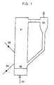
- FIG. 1 An example of the fluidized bed type furnace is disclosed in Japanese Utility Model Publication No. Sho-58-217615. This is illustrated in FIG. 1.
- this furnace includes a cylindrical reducing furnace 91 and a cyclone 95.
- the reducing furnace 91 is provided with a raw iron ore feeding hole 92, a high temperature reducing gas injecting hole 93, and a reduced iron discharge hole 94.
- a gas distributor 96 Further, in the lower portion of the reducing furnace, there is disposed a gas distributor 96. A reducing gas is supplied through the gas distributor 96, and a fine iron ore is supplied through the feeding hole 92.
- the reducing furnace is agitated, so that the fine iron ore and the reducing gas can be mixed so as for the iron ore to be reduced in a fluidized state.
- the fluidized bed takes the form of a bubbling fluidized bed in which the reducing gas forms bubblings, and the bubblings grow while passing through the particle layer.
- the fine iron ore has to be sorted by sieving, or it has to be crushed into the rated sizes.
- the result is that the productivity is lowered, and the production cost is increased, because it requires additional process steps and additional facilities.
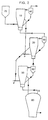
- Korean Patent No. 117065 proposes a 3-stage fluidized bed type reducing apparatus having tapered furnaces as shown in FIG. 2.
- a stable fluidizing of an iron ore of a wide particle size distribution is aimed at, and for this purpose, tapered furnaces are employed.
- first the iron ore is pre-heated, second pre-reduced and then finally reduced, thereby forming a 3-stage reducing process. That is, as shown in FIG. 2, an upper reaction vessel 10 pre-heats the iron ore in a bubbling fluidizing state.
- a middle reaction vessel 20 pre-reduces the iron ore in a bubbling fluidizing state.
- a lower reaction vessel 30 finally reduces the pre-reduced iron ore in a bubbling fluidizing state, thereby completing a continuous 3-stage fluidized bed type process.
- reference codes 40, 50 and 60 indicate cyclones
- reference code 70 indicates a hopper
- 80 indicates a melter-gasifier.
- the present invention is intended to overcome the above described disadvantages of the conventional techniques.
- the 2-stage fluidized bed type apparatus for drying, pre-heating and pre-reducing a fine iron ore in a first fluidized bed type furnace, and for finally reducing the fine iron ore (thus pre-reduced) in a second fluidized bed type furnace according to the present invention includes:
- the method for reducing a fine iron ore by using the above reducing apparatus includes steps wherein : a first fluidized bed type furnace dries, pre-heats and pre-reduces the fine iron ore under a reducing atmosphere; a second fluidized bed type furnace finally reduces the pre-reduced fine iron ore; a hopper and a gas/solid particle sealing valve are installed beneath each of the fluidized bed type furnaces; and the fine iron ore particles dropping through the holes of the gas distributors during an abnormality of operation are circulated back into the fluidized bed type furnaces, whereby the impediment of the gas flow is avoided.
- the 2-stage fluidized bed type fine iron ore reducing apparatus includes:
- the first fluidized bed type furnace 100 includes a lower tapered portion 100a and an upper cylindrical portion 100b. Further, a first gas supply hole 101 is formed on the lower portion of the furnace 100a, for receiving a reducing gas, and within the lower portion of the furnace 100a, there is installed a first gas distributor 102. Further, a first iron ore discharge hole 106 is formed on the side wall of the tapered portion, and the first iron ore discharge hole 106 communicates through a second pipe 103 to the lower portion of the second fluidized bed type furnace 200.
- an iron ore supply hole 105 is formed on the side wall of the tapered portion 100a, and the iron ore supply hole 105 is connected through a first pipe 701 to a hopper 700 to supply the fine iron ore into the first fluidized bed type furnace 100.
- a first gas discharge hole 107 is formed on the top of the furnace 100, and this first gas discharge hole 107 communicates through a third pipe 301 to the upper portion of the first cyclone 300.
- the first cyclone 300 separates the fine iron ore particles from the discharge gas of the first fluidized bed type furnace 100.
- a fourth pipe 302 Through which the separated fine iron ore particles are circulates back to the lower portion of the first fluidized bed type furnace 100.
- a fifth pipe 303 is connected to the top of the first cyclone 300 which finally exhausts the discharge gas from the first fluidized bed type furnace 100.
- the fourth pipe 302 is deeply buried into the first fluidized bed type furnace 100 to recycle the separated fine iron ore particles deeply into the first fluidized bed type furnace 100.
- the second fluidized bed type furnace 200 includes a lower tapered portion 200a and an upper cylindrical portion 200b.
- a second gas supply hole 201 is formed on the lower portion of the tapered portion 200a, for receiving a reducing gas, and a gas distributor 202 is disposed in the lower portion of the tapered portion 200a.
- a second iron ore discharge hole 206 is formed on the side wall of the tapered portion 200a, and the second iron ore discharge hole 206 communicates through an eighth pipe 203 into the melter-gasifier 800.
- a pre-reduced iron ore supply hole 205 is formed on the side wall of the tapered portion 200a, and the pre-reduced iron ore supply hole 205 is connected through the second pipe 103 to the first fluidized bed type furnace 100 to receive the dried, pre-heated and pre-reduced iron ore into the second fluidized bed type furnace 200.
- a second gas discharge hole 207 is formed on the top of the furnace 200, and this second gas discharge hole 207 communicates through a 10th pipe 401 to the second cyclone 400.
- the second cyclone 400 separates the fine iron ore particles from the discharge gas of the second fluidized bed type furnace 200.
- a 9th pipe 402 is connected from the bottom of the second cyclone 400 to the lower portion of the furnace 200, for circulating the separated fine iron ore particles into the furnace 200.
- a 6th pipe 403 is connected to the top of the second cyclone 400, for supplying the discharge gas of the second fluidized bed type furnace 200 to the first fluidized bed type furnace 100.
- the 9th pipe 402 should be preferably buried deeply into the second fluidized bed type furnace 200 to recycle the separated fine iron ore particles deeply into its interior.
- the first intermediate hopper 500 is disposed between the first fluidized bed type furnace 100 and the second fluidized bed type furnace 200.
- the hopper 500 is connected through a seventh pipe 502 to the bottom of the first fluidized bed type furnace 100, and is connected through an 11th pipe 504 into the second fluidized bed type furnace 200.
- the fine iron ore particles which have been dropped through the holes of the gas distributor 102 of the first fluidized bed type furnace 100 can be temporarily stored, and then transported by an inactive gas such as nitrogen into the second fluidized bed type furnace 200.
- the 11th pipe 504 should be preferably deeply buried into the second fluidized bed type furnace 200, and thus, the fine iron ore particles which have been dropped through the holes of the gas distributor 102 of the first fluidized bed type furnace 100 can be recycled deeply into the second fluidized bed type furnace 200.
- the second intermediate hopper 600 is disposed beneath the second fluidized bed type furnace 200, and is connected through a 13th pipe 602 to the bottom of the second fluidized bed type furnace 200, while the hopper 600 is connected through a 12th pipe 604 to the lower portion of the second fluidized bed type furnace 200.
- the fine iron ore particles which have been dropped through the holes of the gas distributor 202 of the second fluidized bed type furnace 200 can be temporarily stored, and then transported by an inactive gas such as nitrogen into the second fluidized bed type furnace 200.
- a fine iron ore which is supplied to the first fluidized bed type furnace 100 is pre-heated and pre-reduced by using a discharge gas (reducing gas) of the second fluidized bed type furnace 200, while forming a bubbling or turbulent fluidized bed.
- the iron ore thus reacted is transferred through a second pipe 103 to the lower portion of the second fluidized bed type furnace 200.
- a final reduction occurs within the second fluidized bed type furnace 200 by forming a bubbling fluidized bed by using a discharge gas (a discharge gas of the melter-gasifier) which is supplied through the second gas supply hole 201.
- the finally reduced iron is discharged through the second iron ore discharge hole 206.
- the fine iron ore particles which are entrained in the discharge gas of the first fluidized bed type furnace 100 are separated from the gas by the first cyclone 300 to be circulated back to the lower portion of the first fluidized bed type furnace 100.
- the fine iron ore particles which are entrained in the discharge gas of the second fluidized bed type furnace 200 are separated from the gas by the second cyclone 400 to be circulated back to the lower portion of the second fluidized bed type furnace 200.
- the fine iron ore particles drop through the holes of the gas distributor to impede the flow of the reducing gas. Therefore, periodically during the operation and at an emergency such the blocking of the reducing gas, first the high temperature valves 501 and 601 (upstream of the first and second intermediate hoppers 500 and 600) are opened. Thus the fine iron ores which are accumulated beneath the gas distributors of the first and second fluidized bed type furnaces 100 and 200 is transferred to the first and second intermediate hoppers 500 and 600, respectively, to be stored there.
- the upstream valves 501 and 601 are closed, and the valves 503 and 603 (downstream of the first and second intermediate hoppers 500 and 600) are opened. Then an inactive gas such as nitrogen is injected to circulate back the stored iron ore into the second fluidized bed type furnace 200.
- an inactive gas such as nitrogen is injected to circulate back the stored iron ore into the second fluidized bed type furnace 200.
- the pre-heating and the pre-reducing within the first fluidized bed type furnace 100 should be carried out preferably at 700 - 850°C, and the final reaction within the second fluidized bed type furnace 200 should be carried out preferably at 750 - 900°C.
- the operating pressure should be preferably 1 - 5 atmospheres in the absolute pressure.
- the superficial gas velocity right above the gas distributors within the first and second fluidized bed type furnaces 100 and 200 should be preferably 1.2 - 2.5 times as fast as the minimum fluidization velocity of the fine iron ore staying within the furnaces, in view of the efficient fluidizing and the elutriation loss of the iron ore particles.
- the angle of the tapered portions should be preferably 5 - 20° relative to the vertical line.
- the height of the tapered portions 100a and 200a above the gas distributors should be preferably 5 - 10 times as large as the diameter of the gas distributors.
- the height of the cylindrical portions 100b and 200b should be preferably 3 - 5 times as large as their own inner diameter.
- a reduction of a fine iron ore was carried out by using a reducing apparatus having a size as shown in Table 1 and at conditions set forth in Tables 2 to 4.
- Height and ID of fluidized bed type furnace First fluidized bed type furnace ID of tapered portion (at the surface of gas distributor) : 0.6 m Angle of tapered portion: 5° Height of tapered portion (from gas distributor): 3 m ID of cylindrical portion: 1.1 m Height of cylindrical portion: 3.5 m
- Second fluidized bed type furnace ID of tapered portion (at the surface of gas distributor) 0.6 m Angle of tapered portion: 5° Height of tapered portion (from gas distributor): 3 m ID of cylindrical portion: 1.1 m Height of cylindrical portion: 3.5 m
- the average gas utilization degree and the gas consumption rate were evaluated.
- the result showed that the gas utilization degree was about 30 - 35%, and the gas consumption rate was 1200 - 1500 Nm 3 /ton-ore.
- the reduction rates of the reduced irons which were discharged through the first and second discharge holes were respectively 30 - 40% and 85 - 95%.
- the iron ore discharge was possible after 60 minutes from feeding the iron ore through the hopper. This shows that the reducing speed is very excellent.
- intermediate hoppers and gas/solid sealing valves are installed beneath the fluidized bed type furnaces.
- the present invention ensures a sufficient reduction rate and a superior gas consumption rate, and is not inferior to Korean Patent 117065 (1997). Further, the present invention is superior over Korean Patent 117065 (1997) in the facility cost and the production cost.
- a relatively uniformly reduced iron can be obtained regardless of the particle sizes of the iron ore.
- the discharge amounts and particle sizes can be adjusted for the respective discharge holes, and the reduction rate can be adjusted by controlling the residence time of the iron ore within the furnace.
Landscapes
- Chemical & Material Sciences (AREA)
- Engineering & Computer Science (AREA)
- Manufacturing & Machinery (AREA)
- Materials Engineering (AREA)
- Metallurgy (AREA)
- Organic Chemistry (AREA)
- Dispersion Chemistry (AREA)
- Manufacture Of Iron (AREA)
- Crucibles And Fluidized-Bed Furnaces (AREA)
- Manufacture And Refinement Of Metals (AREA)
Claims (8)
- Dispositif de type à lit fluidisé à 2 étages pour sécher, pré-chauffer et pré-réduire un minerai de fer fin dans un premier four de type à lit fluidisé, et pour en définitive réduire le minerai de fer fin (ainsi pré-réduit) dans un second four de type à lit fluidisé, comprenant :un premier four conique de type à lit fluidisé 100 pour recevoir un minerai de fer fin brut provenant d'une trémie 700 à travers un premier orifice d'admission de gaz 101 et pour recevoir un gaz réducteur pour former un lit fluidisé à turbulence ou bouillonnant afin de pré-chauffer et de pré-réduire le minerai de fer brut et afin de décharger le minerai de fer fin ainsi pré-réduit à travers un premier orifice de décharge du minorai 106 ;un premier cyclone 300 pour séparer les particules de minerai de fer fin d'un gaz de décharge dudit premier four de type à lit fluidisé 100 pour recycler les particules de minerai de fer fin ainsi séparées dans ledit premier four de type à lit fluidisé 100 ;un second four de type à lit fluidisé 200 pour en dernier lieu réduire le minerai de fer fin (ainsi préchauffé et pré-réduit) dudit premier four de type à lit fluidisé 100, en formant un lit fluidisé à turbulence ou bouillonnant en utilisant un gaz de décharge (gaz réducteur) fourni depuis un gazogène-fondeur 800 à travers un second orifice d'admission de gaz 201, un fer réduit en dernier lieu étant déchargé à travers un second orifice de décharge du minerai de fer 206 ;un second cyclone 400 pour séparer les particules de minerai de fer fin d'un gaz de décharge dudit second four de type à lit fluidisé 200 pour recycler les particules de minerai de fer fin ainsi séparées dans un fond dudit second four de type à lit fluidisé 200 ;une première trémie intermédiaire 500 positionnée entré lesdits premier et second fours de type à lit fluidisé 100 et 200, pour stocker des particules de minerai de fer fin (tombées par les orifices d'un distributeur de gaz 102 dudit premier four de type à lit fluidisé 100) pour les recycler dans une partie inférieure dudit second four de type à lit fluidisé 200 ;une seconde trémie intermédiaire 600 positionnée sous ledit second four de type à lit fluidisé 200, pour stocker des particules de minerai de fer fin (tombées par les orifices d'un distributeur de gaz 202 dudit second four de type à lit fluidisé 200) pour les recycler dans une partie inférieure dudit second four de type à lit fluidisé 200 ;ledit premier orifice de décharge de minerai 106 communiquant par le biais d'un deuxième tuyau 103 avec ledit orifice d'admission du minerai de fer pré-réduit 205 ;ledit premier orifice de décharge de gaz 107 communiquant par le biais d'un troisième tuyau 301 avec une partie supérieure dudit premier cyclone 300, et ledit premier cyclone 300 étant relié par le biais d'un quatrième tuyau 302 au dit premier four conique de type à lit fluidisé 100 ;ledit second cyclone 400 étant relié par le biais d'un dixième tuyau 401 à un haut du second four de type à lit fluidisé 200, relié par le biais d'un neuvième tuyau 402 à une partie inférieure dudit second four de type à lit fluidisé 200, et relié par le biais d'un sixième tuyau 403 à une partie inférieure dudit premier four de type à lit fluidisé 100 ;ladite première trémie intermédiaire 500 étant reliée par le biais d'un septième tuyau 502 à une partie inférieure dudit premier four de type à lit fluidisé 100, et reliée par le biais d'un onzième tuyau 504 à un intérieur dudit second four de type à lit fluidisé 200 ; etladite seconde trémie intermédiaire 600 étant reliée par le biais d'un treizième tuyau 602 à un bas dudit second four de type à lit fluidisé 200, et reliée par le biais d'un douzième tuyau 604 à une partie inférieure dudit second four de type à lit fluidisé 200.
- Dispositif de réduction de minerai de fer fin de type à lit fluidisé à 2 étages selon la revendication 1, dans lequel :ledit quatrième tuyau 302 est enterré en profondeur dans une partie inférieure dudit premier four de type à lit fluidisé 100 pour recycler les particules de minerai de fer fin ainsi séparées en profondeur dans la partie inférieure dudit premier four de type à lit fluidisé 100 ;ledit neuvième tuyau 402 est enterré en profondeur dans une partie inférieure dudit second four de type à lit fluidisé 200 pour recycler les particules de minerai de fer fin ainsi séparées en profondeur dans la partie inférieure dudit second four de type à lit fluidisé 200 ;ledit onzième tuyau 504 est enterré en profondeur dans une partie inférieure dudit second four de type à lit fluidisé 200 pour recycler les particules de minerai de fer fin (tombées par les orifices dudit distributeur de gaz 102) en profondeur dans la partie inférieure dudit second four de type à lit fluidisé 200.
- Dispositif de réduction de minerai de fer fin de type à lit fluidisé à 2 étages selon l'une quelconque des revendications 1 et 2, dans lequel ledit septième tuyau 502, ledit onzième tuyau 504, ledit treizième tuyau 602 et ledit douzième tuyau 604 sont respectivement munis de vannes d'étanchéité gaz/solide haute température 501, 503, 601 et 603.
- Dispositif de réduction de minerai de fer fin de type à lit fluidisé à 2 étages selon l'une quelconque des revendications 1 et 2, dans lequel ledit premier four de type à lit fluidisé 100 et ledit second four de type à lit fluidisé 200 comprennent respectivement une partie conique 100a ou 200a et une partie cylindrique 100b ou 200b ; ladite partie conique a un angle d'inclinaison de 5 à 20° par rapport à une ligne verticale ; ladite partie conique 100a ou 200a a une hauteur (au-dessus dudit distributeur de gaz) 5 à 10 fois supérieure à un diamètre dudit distributeur de gaz ; et ladite partie cylindrique 100b ou 200b a une hauteur 3 à 5 fois supérieure à son diamètre intérieur.
- Dispositif de réduction de minerai de fer fin de type à lit fluidifié à 2 étages selon la revendication 3, dans lequel ledit premier four de type à lit fluidisé 100 et ledit second four de type à lit fluidisé 200 comprennent respectivement une partie conique 100a ou 200a et une partie cylindrique 100b ou 200b ; ladite partie conique a un angle d'inclinaison de 5 à 20° par rapport à une ligne verticale ; ladite partie conique 100a ou 200a a une hauteur (au-dessus dudit distributeur de gaz) 5 à 10 fois supérieure à un diamètre dudit distributeur de gaz ; et ladite partie cylindrique 100b ou 200b a une hauteur 3 à 5 fois supérieure à son diamètre intérieur.
- Procédé pour réduire un minerai de fer fin en utilisant un dispositif de type à lit fluidisé à deux étages pour sécher, pré-chauffer et pré-réduire un minerai de fer fin dans un premier four de type à lit fluidisé, et pour en dernier lieu réduire le minerai de fer fin (ainsi pré-réduit) dans un second four de type à lit fluidisé, comprenant les étapes consistant à :sécher, pré-chauffer et pré-réduire un minerai de fer fin admis à l'intérieur d'un premier four de type à lit fluidisé 100 tout en formant un lit fluidisé bouillonnant ou à turbulence en utilisant un gaz de décharge provenant d'un second four de type à lit fluidisé 200, transférer le minerai de fer fin (ainsi pré-réduit) par le biais d'un deuxième tuyau 103 à une partie inférieure dudit second four de type à lit fluidisé 200, et en dernier lieu réduire le minerai de fer en formant une couche fluidisée bouillonnante en utilisant un gaz réducteur (gaz de décharge d'un gazogène fondeur) après son admission à travers un second orifice d'admission de gaz de décharge 201 ;séparer les particules de minerai de fer extrêmement fin d'un gaz de décharge dudit premier four de type à lit fluidisé 100 par un premier cyclone 300 pour renvoyer les particules de minerai de fer fin (ainsi séparées) jusqu'à une partie inférieure dudit premier four de type à lit fluidisé 100, et séparer les particules de minerai de fer extrêmement fin d'un gaz de décharge dudit second four de type à lit fluidisé 200 par un second cyclone 400 pour renvoyer les particules de minerai de fer fin (ainsi séparées) jusqu'à une partie inférieure dudit second four de type à lit fluidisé 200 ; etouvrir les vannes amont haute température 501 et 601 des première et seconde trémies intermédiaires 500 et 600 dans une situation d'urgence pour stocker les particules de minerai de fer fin accumulées dans lesdites première et seconde trémies intermédiaires 500 et 600, puis fermer lesdites vannes amont haute température 501 et 601 et ouvrir les vannes aval haute température 503 et 603 desdites première et seconde trémies intermédiaires 500 et 600, et injecter un gaz inactif tel que de l'azote pour transférer les particules de minerai de fer fin à une partie inférieure dudit second four de type à lit fluidisé 200.
- Procédé selon la revendication 6, dans lequel une vitesse d'écoulement de gaz juste au-dessus desdits distributeurs de gaz desdits premier et second fours de type à lit fluidisé 100 et 200 est 1,2 à 2,5 fois plus rapide qu'une vitesse de fluidisation minimale des particules de minerai de fer fin restant à l'intérieur desdits fours.
- Procédé selon l'une quelconque des revendications 6 et 7, dans lequel un pré-chauffage et une pré-réduction sont réalisées à l'intérieur dudit premier four de type à lit fluidisé 100 à une température de 700 à 850°C, une réduction finale est réalisée à l'intérieur dudit second four de type à lit fluidisé 200 à une température de 750 à 900°C, et une pression de service de 1 à 5 atmosphères en pression absolue est appliquée aux fours respectifs.
Applications Claiming Priority (1)
| Application Number | Priority Date | Filing Date | Title |
|---|---|---|---|
| PCT/KR1999/000325 WO2000079013A1 (fr) | 1999-06-21 | 1999-06-21 | Appareil de reduction du fin minerai de fer a lits fluidises double etage et procede de reduction faisant appel a cet appareil |
Publications (2)
| Publication Number | Publication Date |
|---|---|
| EP1109940A1 EP1109940A1 (fr) | 2001-06-27 |
| EP1109940B1 true EP1109940B1 (fr) | 2003-08-13 |
Family
ID=19570888
Family Applications (1)
| Application Number | Title | Priority Date | Filing Date |
|---|---|---|---|
| EP99926977A Expired - Lifetime EP1109940B1 (fr) | 1999-06-21 | 1999-06-21 | Appareil de reduction du fin minerai de fer a lits fluidises double etage et procede de reduction faisant appel a cet appareil |
Country Status (11)
| Country | Link |
|---|---|
| US (1) | US6491738B1 (fr) |
| EP (1) | EP1109940B1 (fr) |
| JP (1) | JP3459824B2 (fr) |
| AT (1) | ATE247177T1 (fr) |
| AU (1) | AU746094B2 (fr) |
| CA (1) | CA2341365C (fr) |
| DE (1) | DE69910407T2 (fr) |
| RU (1) | RU2195500C2 (fr) |
| UA (1) | UA46174C2 (fr) |
| WO (1) | WO2000079013A1 (fr) |
| ZA (1) | ZA200102308B (fr) |
Families Citing this family (4)
| Publication number | Priority date | Publication date | Assignee | Title |
|---|---|---|---|---|
| KR100877007B1 (ko) * | 2001-06-19 | 2009-01-07 | 지멘스 브이에이아이 메탈스 테크놀로지스 게엠베하 앤드 컴퍼니 | 입자상 물질을 처리하는 방법 및 장치와 분리 챔버로부터 유동하는 가스의 양을 감소시키는 방법 |
| US8287619B2 (en) * | 2010-06-08 | 2012-10-16 | C.V.G. Ferrominera Orinoco C.A. | Process and equipment for the production of direct reduced iron and/or pig iron from iron ores having a high-phosphorus content |
| KR101353456B1 (ko) * | 2011-12-28 | 2014-01-21 | 주식회사 포스코 | 분철 및 환원철 제조장치 및 그 방법 |
| DE102016103349A1 (de) * | 2016-02-25 | 2017-08-31 | Outotec (Finland) Oy | Verfahren und Vorrichtung zur thermischen Behandlung eines verunreinigten Feststoffes |
Family Cites Families (6)
| Publication number | Priority date | Publication date | Assignee | Title |
|---|---|---|---|---|
| SU846587A1 (ru) * | 1979-10-03 | 1981-07-15 | Институт Черной Металлургии Министерствачерной Металлургии Cccp | Многоступенчатый теплообменник уста-НОВКи дл ВОССТАНОВлЕНи Руд |
| JPS58217615A (ja) | 1982-06-09 | 1983-12-17 | Kawasaki Steel Corp | 溶融還元装置における予備還元炉 |
| WO1996021044A1 (fr) * | 1994-12-29 | 1996-07-11 | Pohang Iron & Steel Co., Ltd. | Appareil de reduction de type a lit fluidise pour minerais de fer et procede de reduction des minerais de fer a l'aide de l'appareil |
| KR970003636B1 (ko) | 1994-12-31 | 1997-03-20 | 포항종합제철 주식회사 | 용융선철 및 용융강 제조시 분철광석을 환원시키는 환원로 |
| KR100256341B1 (ko) * | 1995-12-26 | 2000-05-15 | 이구택 | 분철광석의 2단유동층식 예비환원장치 및 그 방법 |
| KR100213327B1 (ko) | 1995-12-29 | 1999-08-02 | 이구택 | 분철광석의 3단 유동층로식 환원장치 |
-
1999
- 1999-06-21 JP JP2001505356A patent/JP3459824B2/ja not_active Expired - Fee Related
- 1999-06-21 AT AT99926977T patent/ATE247177T1/de active
- 1999-06-21 AU AU43987/99A patent/AU746094B2/en not_active Ceased
- 1999-06-21 DE DE1999610407 patent/DE69910407T2/de not_active Expired - Lifetime
- 1999-06-21 CA CA 2341365 patent/CA2341365C/fr not_active Expired - Fee Related
- 1999-06-21 RU RU2001107608A patent/RU2195500C2/ru not_active IP Right Cessation
- 1999-06-21 WO PCT/KR1999/000325 patent/WO2000079013A1/fr not_active Ceased
- 1999-06-21 EP EP99926977A patent/EP1109940B1/fr not_active Expired - Lifetime
- 1999-06-21 UA UA2001031886A patent/UA46174C2/uk unknown
- 1999-06-21 US US09/763,299 patent/US6491738B1/en not_active Expired - Fee Related
-
2001
- 2001-03-20 ZA ZA200102308A patent/ZA200102308B/en unknown
Also Published As
| Publication number | Publication date |
|---|---|
| JP2003502503A (ja) | 2003-01-21 |
| CA2341365A1 (fr) | 2000-12-28 |
| ZA200102308B (en) | 2002-01-28 |
| AU746094B2 (en) | 2002-04-18 |
| WO2000079013A1 (fr) | 2000-12-28 |
| AU4398799A (en) | 2001-01-09 |
| DE69910407T2 (de) | 2004-07-08 |
| US6491738B1 (en) | 2002-12-10 |
| DE69910407D1 (de) | 2003-09-18 |
| UA46174C2 (uk) | 2002-05-15 |
| ATE247177T1 (de) | 2003-08-15 |
| JP3459824B2 (ja) | 2003-10-27 |
| CA2341365C (fr) | 2005-04-12 |
| EP1109940A1 (fr) | 2001-06-27 |
| RU2195500C2 (ru) | 2002-12-27 |
Similar Documents
| Publication | Publication Date | Title |
|---|---|---|
| US5762681A (en) | Fluidized bed type reduction apparatus for iron ores and method for reducing iron ores using the apparatus | |
| US5198019A (en) | Manufacture of iron and steel in a duplex smelter and solid state oxide suspension prereducer | |
| US6110413A (en) | 3-Stage fluidized bed type fine iron ore reducing apparatus having x-shaped circulating tubes | |
| CZ178294A3 (en) | Reducing process of a material containing metal oxide in a solid state | |
| EP1109940B1 (fr) | Appareil de reduction du fin minerai de fer a lits fluidises double etage et procede de reduction faisant appel a cet appareil | |
| KR100332924B1 (ko) | 분철광석의 점착을 방지할 수 있는 3단 유동층식 환원장치및 이를 이용한 환원방법 | |
| US6235079B1 (en) | Two step twin-single fluidized bed pre-reduction apparatus for pre-reducing fine iron ore, and method therefor | |
| CA2320242A1 (fr) | Appareil de reduction de minerai de fer fin de type a lit fluidise et procede afferent | |
| KR100236198B1 (ko) | 2단의 분철광석의 유동층식 환원장치 및 그 방법 | |
| KR100286687B1 (ko) | 분철광석을 이용한 용선제조장치 | |
| US5227116A (en) | Manufacture of iron and steel in a duplex smelter and solid state oxide suspension prereducer | |
| CA2322130A1 (fr) | Appareil et procede de reduction de minerai de fer fin, du type a lit fluidise complexe | |
| KR100321049B1 (ko) | 분철광석의유동층식환원방법및그환원장치 |
Legal Events
| Date | Code | Title | Description |
|---|---|---|---|
| PUAI | Public reference made under article 153(3) epc to a published international application that has entered the european phase |
Free format text: ORIGINAL CODE: 0009012 |
|
| 17P | Request for examination filed |
Effective date: 20010216 |
|
| AK | Designated contracting states |
Kind code of ref document: A1 Designated state(s): AT DE GB IT LU SE |
|
| GRAH | Despatch of communication of intention to grant a patent |
Free format text: ORIGINAL CODE: EPIDOS IGRA |
|
| GRAH | Despatch of communication of intention to grant a patent |
Free format text: ORIGINAL CODE: EPIDOS IGRA |
|
| GRAA | (expected) grant |
Free format text: ORIGINAL CODE: 0009210 |
|
| AK | Designated contracting states |
Designated state(s): AT DE GB IT LU SE |
|
| REG | Reference to a national code |
Ref country code: GB Ref legal event code: FG4D |
|
| REF | Corresponds to: |
Ref document number: 69910407 Country of ref document: DE Date of ref document: 20030918 Kind code of ref document: P |
|
| REG | Reference to a national code |
Ref country code: SE Ref legal event code: TRGR |
|
| PLBE | No opposition filed within time limit |
Free format text: ORIGINAL CODE: 0009261 |
|
| STAA | Information on the status of an ep patent application or granted ep patent |
Free format text: STATUS: NO OPPOSITION FILED WITHIN TIME LIMIT |
|
| 26N | No opposition filed |
Effective date: 20040514 |
|
| PGFP | Annual fee paid to national office [announced via postgrant information from national office to epo] |
Ref country code: AT Payment date: 20120411 Year of fee payment: 14 |
|
| PGFP | Annual fee paid to national office [announced via postgrant information from national office to epo] |
Ref country code: GB Payment date: 20130530 Year of fee payment: 15 Ref country code: SE Payment date: 20130524 Year of fee payment: 15 Ref country code: DE Payment date: 20130524 Year of fee payment: 15 Ref country code: LU Payment date: 20130529 Year of fee payment: 15 |
|
| PGFP | Annual fee paid to national office [announced via postgrant information from national office to epo] |
Ref country code: IT Payment date: 20130524 Year of fee payment: 15 |
|
| REG | Reference to a national code |
Ref country code: DE Ref legal event code: R119 Ref document number: 69910407 Country of ref document: DE |
|
| PG25 | Lapsed in a contracting state [announced via postgrant information from national office to epo] |
Ref country code: LU Free format text: LAPSE BECAUSE OF NON-PAYMENT OF DUE FEES Effective date: 20140621 Ref country code: SE Free format text: LAPSE BECAUSE OF NON-PAYMENT OF DUE FEES Effective date: 20140622 |
|
| REG | Reference to a national code |
Ref country code: SE Ref legal event code: EUG |
|
| REG | Reference to a national code |
Ref country code: AT Ref legal event code: MM01 Ref document number: 247177 Country of ref document: AT Kind code of ref document: T Effective date: 20140621 |
|
| GBPC | Gb: european patent ceased through non-payment of renewal fee |
Effective date: 20140621 |
|
| REG | Reference to a national code |
Ref country code: DE Ref legal event code: R119 Ref document number: 69910407 Country of ref document: DE Effective date: 20150101 |
|
| PG25 | Lapsed in a contracting state [announced via postgrant information from national office to epo] |
Ref country code: DE Free format text: LAPSE BECAUSE OF NON-PAYMENT OF DUE FEES Effective date: 20150101 Ref country code: IT Free format text: LAPSE BECAUSE OF NON-PAYMENT OF DUE FEES Effective date: 20140621 |
|
| PG25 | Lapsed in a contracting state [announced via postgrant information from national office to epo] |
Ref country code: AT Free format text: LAPSE BECAUSE OF NON-PAYMENT OF DUE FEES Effective date: 20140621 Ref country code: GB Free format text: LAPSE BECAUSE OF NON-PAYMENT OF DUE FEES Effective date: 20140621 |