EP1110029B1 - Leuchtende anzeigetafel - Google Patents
Leuchtende anzeigetafel Download PDFInfo
- Publication number
- EP1110029B1 EP1110029B1 EP99932933A EP99932933A EP1110029B1 EP 1110029 B1 EP1110029 B1 EP 1110029B1 EP 99932933 A EP99932933 A EP 99932933A EP 99932933 A EP99932933 A EP 99932933A EP 1110029 B1 EP1110029 B1 EP 1110029B1
- Authority
- EP
- European Patent Office
- Prior art keywords
- layer
- plate
- display backlight
- sub
- backlight according
- Prior art date
- Legal status (The legal status is an assumption and is not a legal conclusion. Google has not performed a legal analysis and makes no representation as to the accuracy of the status listed.)
- Expired - Lifetime
Links
- 239000000463 material Substances 0.000 claims description 24
- 230000003287 optical effect Effects 0.000 claims description 24
- 239000003292 glue Substances 0.000 claims description 6
- 239000000049 pigment Substances 0.000 claims description 6
- 230000008878 coupling Effects 0.000 claims description 4
- 238000010168 coupling process Methods 0.000 claims description 4
- 238000005859 coupling reaction Methods 0.000 claims description 4
- 238000009826 distribution Methods 0.000 claims description 3
- 239000002904 solvent Substances 0.000 claims description 2
- 230000000644 propagated effect Effects 0.000 claims 4
- 230000002093 peripheral effect Effects 0.000 claims 3
- XLYOFNOQVPJJNP-UHFFFAOYSA-N water Substances O XLYOFNOQVPJJNP-UHFFFAOYSA-N 0.000 claims 1
- 239000010410 layer Substances 0.000 description 45
- 239000000853 adhesive Substances 0.000 description 7
- 230000001070 adhesive effect Effects 0.000 description 6
- 239000012780 transparent material Substances 0.000 description 6
- 230000005540 biological transmission Effects 0.000 description 3
- 239000004926 polymethyl methacrylate Substances 0.000 description 3
- 239000011521 glass Substances 0.000 description 2
- 238000004519 manufacturing process Methods 0.000 description 2
- 238000005259 measurement Methods 0.000 description 2
- 229920003229 poly(methyl methacrylate) Polymers 0.000 description 2
- 238000000926 separation method Methods 0.000 description 2
- 239000007787 solid Substances 0.000 description 2
- 229920005440 Altuglas® Polymers 0.000 description 1
- 229920000297 Rayon Polymers 0.000 description 1
- RTAQQCXQSZGOHL-UHFFFAOYSA-N Titanium Chemical compound [Ti] RTAQQCXQSZGOHL-UHFFFAOYSA-N 0.000 description 1
- 239000012790 adhesive layer Substances 0.000 description 1
- 238000000149 argon plasma sintering Methods 0.000 description 1
- 239000000835 fiber Substances 0.000 description 1
- 238000002513 implantation Methods 0.000 description 1
- 239000000976 ink Substances 0.000 description 1
- 229910052500 inorganic mineral Inorganic materials 0.000 description 1
- 238000000034 method Methods 0.000 description 1
- 239000011707 mineral Substances 0.000 description 1
- 239000000203 mixture Substances 0.000 description 1
- 229910052754 neon Inorganic materials 0.000 description 1
- GKAOGPIIYCISHV-UHFFFAOYSA-N neon atom Chemical compound [Ne] GKAOGPIIYCISHV-UHFFFAOYSA-N 0.000 description 1
- 239000013307 optical fiber Substances 0.000 description 1
- 239000003973 paint Substances 0.000 description 1
- 239000002245 particle Substances 0.000 description 1
- 239000004033 plastic Substances 0.000 description 1
- 229920003023 plastic Polymers 0.000 description 1
- 229920000728 polyester Polymers 0.000 description 1
- 230000001902 propagating effect Effects 0.000 description 1
- 239000002964 rayon Substances 0.000 description 1
- 238000009877 rendering Methods 0.000 description 1
- 230000005477 standard model Effects 0.000 description 1
- 229910052719 titanium Inorganic materials 0.000 description 1
- 239000010936 titanium Substances 0.000 description 1
- 230000000007 visual effect Effects 0.000 description 1
Images



Classifications
-
- G—PHYSICS
- G02—OPTICS
- G02B—OPTICAL ELEMENTS, SYSTEMS OR APPARATUS
- G02B6/00—Light guides; Structural details of arrangements comprising light guides and other optical elements, e.g. couplings
- G02B6/0001—Light guides; Structural details of arrangements comprising light guides and other optical elements, e.g. couplings specially adapted for lighting devices or systems
- G02B6/0011—Light guides; Structural details of arrangements comprising light guides and other optical elements, e.g. couplings specially adapted for lighting devices or systems the light guides being planar or of plate-like form
- G02B6/0013—Means for improving the coupling-in of light from the light source into the light guide
- G02B6/0023—Means for improving the coupling-in of light from the light source into the light guide provided by one optical element, or plurality thereof, placed between the light guide and the light source, or around the light source
-
- G—PHYSICS
- G02—OPTICS
- G02B—OPTICAL ELEMENTS, SYSTEMS OR APPARATUS
- G02B6/00—Light guides; Structural details of arrangements comprising light guides and other optical elements, e.g. couplings
- G02B6/0001—Light guides; Structural details of arrangements comprising light guides and other optical elements, e.g. couplings specially adapted for lighting devices or systems
- G02B6/0011—Light guides; Structural details of arrangements comprising light guides and other optical elements, e.g. couplings specially adapted for lighting devices or systems the light guides being planar or of plate-like form
- G02B6/0033—Means for improving the coupling-out of light from the light guide
- G02B6/005—Means for improving the coupling-out of light from the light guide provided by one optical element, or plurality thereof, placed on the light output side of the light guide
-
- G—PHYSICS
- G02—OPTICS
- G02B—OPTICAL ELEMENTS, SYSTEMS OR APPARATUS
- G02B6/00—Light guides; Structural details of arrangements comprising light guides and other optical elements, e.g. couplings
- G02B6/0001—Light guides; Structural details of arrangements comprising light guides and other optical elements, e.g. couplings specially adapted for lighting devices or systems
- G02B6/0011—Light guides; Structural details of arrangements comprising light guides and other optical elements, e.g. couplings specially adapted for lighting devices or systems the light guides being planar or of plate-like form
- G02B6/0033—Means for improving the coupling-out of light from the light guide
- G02B6/0035—Means for improving the coupling-out of light from the light guide provided on the surface of the light guide or in the bulk of it
- G02B6/004—Scattering dots or dot-like elements, e.g. microbeads, scattering particles, nanoparticles
- G02B6/0043—Scattering dots or dot-like elements, e.g. microbeads, scattering particles, nanoparticles provided on the surface of the light guide
Definitions
- the present invention relates to illuminated display panels which allow you to view any message in the visible light domain, and more particularly, but not exclusively, signs for advertising or similar use.
- GB-A-2 168 519 which relates to a display panel generally comprising a plate made in a transparent material, on which are arranged one or more parts made in another transparent material, and a light source coupled with the edge of the plate. Light propagates in the plate by successive total reflections and emerges of the plate at the places comprising the said part or parts to make the latter luminous over their entire surface and visible to people watching the plate substantially from the front. Said parts of transparent material are constituted a translucent support comprising diffusing particles of the pigment type.
- This guy display has a modest yield as to the amount of light captured by said parts made of transparent material.
- the implantation of pigments in solid parts like those described in this document present difficulties production and implementation techniques.
- the object of the present invention is therefore to produce a display panel luminous whose structure overcomes the disadvantages mentioned above of the panels of prior art.
- Figures 1 to 6 show different embodiments of the luminous display panel according to the invention, the same references designate the same elements whatever the figure on which they appear and whatever the representation of these elements.
- the object of the invention comprises "at least one" element having a given function
- the mode of embodiment described may include several of these elements.
- FIGS. 1 and 2 represent a first embodiment of a luminous display panel 1 capable of being placed in a medium 2 of optical index of value n 1 , like air, the value of n 1 being in this case equal to 1.
- the panel 1 comprises a plate 10 made of a first material transparent for at least one light wavelength in the passband of the visible.
- This first material has an optical index of a value n 2 greater than the value n 1 .
- It is for example constituted by organic or mineral glass, PMMA, or by a material known under the trade name "Altuglas", etc.
- the plate 10 is delimited by two flat faces 11, 12 advantageously substantially parallel and having a substantially optical polish, and by a slice of border 13.
- the panel further comprises a visible light source 14, for example a lamp emitting in the visible domain such as a neon lamp, or the like.
- It also includes means 15 for coupling the output of the source of visible light 14 with the edge edge 13 of the plate 10 so that the rays light 16 emitted by the visible light source can penetrate the plate by this edge slice and spread inside the plate between the two faces planes 11, 12 mainly by a succession of total reflections, as is produced in optical fibers or the like.
- These coupling means can be different types, for example lenses, focusers, waveguides bright, etc. They are well known in themselves by those skilled in the art and will not be not more fully described here, for the sole purpose of simplifying the present description.
- the panel also comprises at least a first layer 20 produced in a second transparent material for the wavelength mentioned above and disposed in optical contact with a first 11 of the two flat faces 11, 12 of the plate 10.
- This second material for example plastic material such as PVC, polyester, etc., has an optical index of a value n 3 which is greater than at least the value n 1 and even advantageously, if possible, greater than the value n 2 .
- Means 40 are further provided for diffusing the light capable of propagate in the first layer 20.
- These light scattering means 40 can for example be constituted by a frosted 41 produced on the face 29 of the first layer 20 which is not in contact with the first face 11 of the plate 10, this frosted 41 being schematically represented by a dashed line, and / or by dots white opaque materials 42 contained in the first layer 20.
- the points of white opaque materials 42 are for example constituted by a grid, a degraded frame or not, or the like, embedded in this first layer.
- the illuminated display panel can comprise, as illustrated in FIGS. 1 and 2, a second layer 50 produced in a reflective material for the wavelength mentioned above, this second layer 50 being deposited on the second face 12 of the plate 10.
- the luminous display panel a first embodiment of which was described above with reference to Figures 1 and 2 operates as follows:
- the first layer 20 is made of a single material which has an optical index of a value n 3 greater than the value n 2 , that the optical index n 1 is that of air , that is to say equal to 1, and that the index n 2 greater than 1 is for example equal to 1.52, that of glass.
- the lamp 14 is lit so that the light rays 16 which it emits propagate inside the plate 10 by undergoing a succession of total reflections on the two plane faces 11, 12, owing to the fact that those these are relatively well polished and that they form separation diopters between an incident medium of optical index n 2 greater than the index n 1 of the external medium constituted by air.
- the birth of the refracted rays 16-1 is favored by an optical index n 3 of the first layer 20 greater than the optical index n 2 of the plate 10.
- n 3 is between n 1 and n 2 , the refraction will be less important but will nevertheless exist.
- the refracted rays 16-1 then fall on the frosted surface 29 and undergo diffraction by transmission 16-3 and by reflection 16-4. Like the rays diffracted by 16-3 transmission are distributed in a relatively solid angle important, many of these radii are necessarily substantially normal in terms of the face 29 and can emerge from the first layer 20 then propagate in the air and thus be captured, for example, by the eye 60 of an observer.
- the phenomenon described above occurs on the entire face 29 of the layer 20 and the observer can perceive the luminous object 22 formed by the first layer 20 on plate 10.
- the first layer 20 has the forms an "L” and, in this case, the observer will perceive this luminous "L” without perceiving significantly all the rest of the face 11 of the plate 10, especially if this face has the optical polish necessary to prevent the beams propagating inside the plate only emerges, if only partially, from this face 11.
- the first layer 20 defined above has been described as being unitary. However, it is obvious that it can be constituted in different ways, in particular as that which is illustrated in the two figures 1 and 2.
- This first layer 20 is in fact, according to the invention constituted by the superposition, one on the other, at least two first and second sub-layers 21, 32 produced, as to their respective thickness and the materials constituting them, so that, together, they are optically equivalent to the first layer 20.
- first sub-layer 21 is arranged perfectly at the optical contact on the first face 11 of the plate 10. It can thus be constituted by glue allowing the second underlay 32 to adhere perfectly to the first face 11 of the plate 10.
- the first sub-layer 21 can be constituted by aqueous or solvent based glue.
- the second underlay 32 it can be formed by a mixture of an adhesive, for example that constituting the first sublayer 21, with white pigments, for example white of titanium, so as to obtain a second perfectly self-adhesive undercoat on the first undercoat and thus form, with the set of two undercoats, an adhesive white and opaque adhesive adhering to the first face 11 of the plate 10.
- This assembly in fact constitutes the first layer 20 as defined above. further comprising the frosted 41 constituted for example as mentioned above by a grid, a degraded frame or not, or the like.
- This first layer 20 allows therefore to conduct light like a light waveguide.
- This first layer 20 allows to obtain, with particular structural realizations, different light distributions.
- this first layer 20 with the frosted 41 is present in the form of strips, for example in line, these strips being produced according to the formats of the panels but always obeying a specific standard model.
- these bands are perpendicular to the axes of the light tubes fluorescent which are arranged parallel to the edge edge 13.
- these bands may have a section, taken opposite these tubes, relatively small value to arrive at larger sections at the level substantially from the center of the plate or on a central axis thereof, the space included between two bands being determined so as to obtain the desired visual rendering for a desired light distribution.
- FIGS 4, 5 and 6 show possible embodiments of plates 10 with their first layer 20 as defined above.
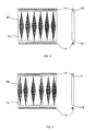
- Figure 4 shows a light panel comprising a plate 10 whose borders 13 are lit by two fluorescent light tubes 14 placed on two opposite sides of the plate 10, with parallel strips, as described above, regularly spaced.
- FIG. 5 shows a light panel comprising a plate 10 whose borders 13 are lit by two fluorescent light tubes 14 placed on two opposite sides of the plate 10, with parallel strips as described above, irregularly spaced, the bands closest to the unlit edges of the plate being closer to each other.
- Figure 6 shows a light panel comprising a plate 10 whose borders 13 are lit by four fluorescent light tubes 14 placed on the four sides of the plate 10, the strips being perpendicular to the axis of the tubes as described above up to the diagonals of the plate 10, as shown in FIG. 6.
- the applicant established the mean luminance on a PMMA plate 620 mm by 860 mm and 12 mm thick, according to lighting and strips of the type of that shown in FIG. 4;
- the two fluorescent tubes are tubes with a power of 30 Watts and a length of 900 mm, and the luminance measurements were carried out on the side of the face of the plate opposite to that carrying the strips;
- the strips have a width of about 0.075 mm near the edges 13 and a width of 1.5 mm on a center line of the plate where they are widest, forming a total area of about 0.119 m 2 for a the surface of the plate equal to 0.533 m 2 ;
- the regular spacing of the strips is 3.5 mm taken near the edges 13;
- the luminance measurements at different points of the plate and at a distance of two meters from it, in a direction perpendicular to the face of the plate made it possible to establish an average luminance of the plate of 405 Cd / m 2 .
- Layer 20 can also consist of a layer of adhesive on one side which is fixed a frame which can be a layer of ink, paint or fibers.
- the adhesive and the integral frame can be produced in the form of a sheet which will be fixed by simple pressure on one face of the plate 10, via the face of the adhesive layer opposite to that carrying the weft.
- the eye 60 of the observer picks up the beams 16-3 diffracted by transmission.
- the observer must be positioned on the side of the plate 20 opposite its face 12 which carries the reflective layer 50.
- the display panel light does not have a second reflective layer 50 on the second face 12 of the plate 10.
- the observer can then pick up the beams 16-4 diffracted by reflection on the face 29 of the first layer 20.
- the eye 70 can be placed the other side of the plate 10 relative to its position for the embodiment according to Figures 1 and 2.
- the first layer 20 then covers the entire first face 11 of the plate 10 and thus allows to illuminate, from behind in the manner of a slide, a image 71 positioned opposite the second face 12 of the plate.
Landscapes
- Physics & Mathematics (AREA)
- General Physics & Mathematics (AREA)
- Optics & Photonics (AREA)
- Illuminated Signs And Luminous Advertising (AREA)
- Planar Illumination Modules (AREA)
Claims (10)
- Leucht-Anzeigetafel (1) für die Anordnung in einer Umgebung (2) mit einem Brechungsindex mit dem Wert n1, umfassend:dadurch gekennzeichnet, dass die erste Schicht (20) durch die Überlagerung von mindestens zwei Unterschichten, einer ersten und einer zweiten (21, 32), gebildet wird, wobei diese Unterschichten hinsichtlich ihrer jeweiligen Dicke und ihres Materials derart ausgebildet sind, dass sie gemeinsam der ersten Schicht entsprechen, wobei die erste Unterschicht (21) in optischem Kontakt auf der ersten Fläche (11) der Platte (10) angeordnet ist, wobei die erste Unterschicht (21) aus Klebstoff gebildet ist, der ein Anhaften der zweiten Unterschicht (32) auf der ersten Fläche (11) der Platte erlaubt, wobei die zweite Unterschicht (32) aus Klebstoff gebildet ist, der mit Pigmenten versetzt ist.eine Platte (10) aus einem ersten Material, das für Licht mindestens einer Wellenlänge innerhalb des Durchgangsbereichs des sichtbaren Lichts transparent ist, wobei das erste Material einen Brechungsindex mit dem Wert n2 größer als n1 hat, wobei die Platte durch zwei ebene Flächen (11, 12), die im wesentlichen parallel sind und eine im Wesentlichen optische Politur aufweisen, und durch eine Abschlussscheibe (13) bestimmt ist,eine Quelle sichtbaren Lichts (14),Mittel (15) zum Koppeln dieser Quelle sichtbaren Lichts (14) mit der Abschlussscheibe (13) der Platte (10), derart, dass die von der Quelle sichtbaren Lichts ausgesendeten Strahlen (16) durch diese Abschlussscheibe (13) in die Platte eindringen und sich im Innern der Platte zwischen den beiden ebenen Flächen (11, 12) im Wesentlichen über Totalreflexionen ausbreiten, undmindestens eine erste Schicht (20) aus einem zweiten für Licht dieser Wellenlänge transparenten Material, wobei die erste Schicht in optischem Kontakt zu einer ersten (11) derbeiden ebenen Flächen (11,12) der Platte (10) angeordnet ist, wobei dieses zweite Material einen Brechungsindex mit dem Wert n3 größer als n1 hat,
- Tafel nach Anspruch 1,
dadurch gekennzeichnet, dass die erste Unterschicht (21) von Klebstoff auf wässriger oder Lösemittelbasis gebildet ist. - Tafel nach einem der Ansprüche 1 und 2,
dadurch gekennzeichnet, dass der Wert n3 größer ist als der Wert n2. - Tafel nach einem der Ansprüche 1 bis 3,
dadurch gekennzeichnet, dass die erste Schicht (20) ferner Mittel (40) aufweist für die Streuung des Lichts, das sich in ihr ausbreiten kann. - Tafel nach Anspruch 4,
dadurch gekennzeichnet, dass die Mittel zur Streuung des Lichts, das sich in der ersten Schicht (20) ausbreiten kann, aus einer Mattienmg (41) bestehen, die auf der Fläche (29) dieser ersten Schicht (20) ausgebildet ist, die keinen Kontakt mit der ersten Fläche (11) der Platte (10) hat. - Tafel nach Anspruch 4,
dadurch gekennzeichnet, dass die Mittel zur Streuung des Lichts, das sich in der ersten Schicht (20) ausbreiten kann, von Punkten aus lichtundurchlässigem Material (42) gebildet sind, die in der ersten Schicht enthalten sind. - Tafel nach Anspruch 6,
dadurch gekennzeichnet, dass die Punkte aus lichtundurchlässigem Material (42) durch ein Gitter oder ein Raster gebildet werden, das in die erste Schicht (20) eingebettet ist. - Tafel nach einem der Ansprüche 1 bis 7,
dadurch gekennzeichnet, dass sie eine zweite Schicht (50) aus einem für Licht dieser Wellenlänge reflektierenden Material aufweist, die auf der zweiten Fläche (12) der Platte (10) angeordnet ist. - Tafel nach einem der Ansprüche 1 bis 8,
dadurch gekennzeichnet, dass sie eine dritte Schicht (51) aus einem für Licht dieser Wellenlänge reflektierenden Material aufweist, die auf der Fläche (29) der ersten Schicht (20) aufliegt, die keinen Kontakt mit der ersten Fläche (11) der Platte (10) hat. - Tafel nach einem der Ansprüche 1 bis 9,
dadurch gekennzeichnet, dass die erste Schicht (20) die Form von Streifen aufweist, deren Querschnitte zum Erreichen einer bestimmten Verteilung des ausgesendeten Lichts angepasst sind.
Applications Claiming Priority (3)
| Application Number | Priority Date | Filing Date | Title |
|---|---|---|---|
| FR9810731 | 1998-08-26 | ||
| FR9810731A FR2782829B1 (fr) | 1998-08-26 | 1998-08-26 | Panneaux d'affichage lumineux |
| PCT/FR1999/001786 WO2000012930A1 (fr) | 1998-08-26 | 1999-07-21 | Panneaux d'affichage lumineux |
Publications (2)
| Publication Number | Publication Date |
|---|---|
| EP1110029A1 EP1110029A1 (de) | 2001-06-27 |
| EP1110029B1 true EP1110029B1 (de) | 2004-01-07 |
Family
ID=9529891
Family Applications (1)
| Application Number | Title | Priority Date | Filing Date |
|---|---|---|---|
| EP99932933A Expired - Lifetime EP1110029B1 (de) | 1998-08-26 | 1999-07-21 | Leuchtende anzeigetafel |
Country Status (7)
| Country | Link |
|---|---|
| US (1) | US6536909B1 (de) |
| EP (1) | EP1110029B1 (de) |
| AU (1) | AU4914399A (de) |
| DE (1) | DE69914089T2 (de) |
| ES (1) | ES2213374T3 (de) |
| FR (1) | FR2782829B1 (de) |
| WO (1) | WO2000012930A1 (de) |
Cited By (1)
| Publication number | Priority date | Publication date | Assignee | Title |
|---|---|---|---|---|
| DE102018114845B4 (de) | 2017-06-22 | 2025-03-27 | Xerox Corporation | Anzeigevorrichtungskomponente und verfahren zum herstellen der anzeigevorrichtungskomponente |
Families Citing this family (23)
| Publication number | Priority date | Publication date | Assignee | Title |
|---|---|---|---|---|
| US7289083B1 (en) * | 2000-11-30 | 2007-10-30 | Palm, Inc. | Multi-sided display for portable computer |
| US8384674B1 (en) | 2001-01-30 | 2013-02-26 | Hewlett-Packard Development Company, L.P. | Integrated enclosure/touch screen assembly |
| US7348964B1 (en) * | 2001-05-22 | 2008-03-25 | Palm, Inc. | Single-piece top surface display layer and integrated front cover for an electronic device |
| RU2001125705A (ru) * | 2001-02-23 | 2004-01-10 | Валерий Николаевич Бурцев (UA) | Устройство для демонстрации информации |
| US6992659B2 (en) | 2001-05-22 | 2006-01-31 | Palmone, Inc. | High transparency integrated enclosure touch screen assembly for a portable hand held device |
| US7142195B2 (en) | 2001-06-04 | 2006-11-28 | Palm, Inc. | Interface for interaction with display visible from both sides |
| US7852430B1 (en) * | 2001-11-29 | 2010-12-14 | Palm, Inc. | Light guide spacers for backlighting a reflective display |
| FR2858705B1 (fr) * | 2003-08-05 | 2005-11-11 | Excel Light | Panneau lumineux et application aux ecrans de visualisation du type video |
| US7719021B2 (en) * | 2005-06-28 | 2010-05-18 | Lighting Science Group Corporation | Light efficient LED assembly including a shaped reflective cavity and method for making same |
| WO2007002476A2 (en) | 2005-06-28 | 2007-01-04 | Lamina Ceramics, Inc. | Backlight module display with optical coupler and lightguide |
| DE202006017445U1 (de) * | 2006-11-14 | 2007-08-02 | Demmel Ag | Lichtmodul, insbesondere für einen hinterleuchtbaren Schriftzug in einer Frontblende |
| CN101779148B (zh) | 2007-06-14 | 2014-06-25 | 艾利丹尼森公司 | 受照图形和信息显示器 |
| US20120127751A1 (en) * | 2008-11-10 | 2012-05-24 | Nokia Corporation | Diffractive backlight structure |
| CA2787142A1 (en) * | 2009-01-14 | 2010-07-22 | Abl Ip Holding, Llc | Luminaire having floating luminous light source |
| US20100302799A1 (en) * | 2009-05-29 | 2010-12-02 | Nokia Corporation | Moving light effect using a light-guide structure |
| DE102009027288A1 (de) | 2009-06-29 | 2010-12-30 | Evonik Röhm Gmbh | Lichtleitplatte mit eingebetteten lichtstreuenden Störstellen und Verfahren zu dessen Herstellung |
| TWI405102B (zh) * | 2009-10-07 | 2013-08-11 | Radiant Opto Electronics Corp | 背光模組與光學式觸控面板 |
| WO2012059855A1 (en) * | 2010-11-03 | 2012-05-10 | Koninklijke Philips Electronics N.V. | Light emitting sheet |
| TWI485479B (zh) * | 2013-03-15 | 2015-05-21 | Au Optronics Corp | 具拼接反射面之背光模組 |
| TW201447434A (zh) * | 2013-06-11 | 2014-12-16 | Au Optronics Corp | 背光模組 |
| EP3025092B1 (de) | 2013-07-22 | 2017-05-17 | Evonik Röhm GmbH | Lichtleitplatte und verfahren zu deren herstellung |
| US20150285445A1 (en) * | 2014-04-07 | 2015-10-08 | Crayola Llc | Window Glow Device |
| EP3002508A1 (de) | 2014-09-30 | 2016-04-06 | Evonik Röhm GmbH | Lichtverbundsystem für die Verwendung in ultradünnen Leuchten und Back Light Units |
Family Cites Families (4)
| Publication number | Priority date | Publication date | Assignee | Title |
|---|---|---|---|---|
| US3491245A (en) * | 1967-04-10 | 1970-01-20 | George K C Hardesty | Guided light display panel |
| GB2168519A (en) * | 1984-12-12 | 1986-06-18 | Globetech Ltd | Display device |
| US5760858A (en) * | 1995-04-21 | 1998-06-02 | Texas Instruments Incorporated | Field emission device panel backlight for liquid crystal displays |
| FR2741180B1 (fr) * | 1995-11-10 | 1998-02-06 | Epsilon | Panneau luminescent |
-
1998
- 1998-08-26 FR FR9810731A patent/FR2782829B1/fr not_active Expired - Fee Related
-
1999
- 1999-07-21 DE DE1999614089 patent/DE69914089T2/de not_active Expired - Lifetime
- 1999-07-21 AU AU49143/99A patent/AU4914399A/en not_active Abandoned
- 1999-07-21 ES ES99932933T patent/ES2213374T3/es not_active Expired - Lifetime
- 1999-07-21 WO PCT/FR1999/001786 patent/WO2000012930A1/fr not_active Ceased
- 1999-07-21 US US09/763,467 patent/US6536909B1/en not_active Expired - Fee Related
- 1999-07-21 EP EP99932933A patent/EP1110029B1/de not_active Expired - Lifetime
Cited By (1)
| Publication number | Priority date | Publication date | Assignee | Title |
|---|---|---|---|---|
| DE102018114845B4 (de) | 2017-06-22 | 2025-03-27 | Xerox Corporation | Anzeigevorrichtungskomponente und verfahren zum herstellen der anzeigevorrichtungskomponente |
Also Published As
| Publication number | Publication date |
|---|---|
| DE69914089T2 (de) | 2004-11-18 |
| AU4914399A (en) | 2000-03-21 |
| FR2782829B1 (fr) | 2000-11-10 |
| DE69914089D1 (de) | 2004-02-12 |
| ES2213374T3 (es) | 2004-08-16 |
| EP1110029A1 (de) | 2001-06-27 |
| WO2000012930A1 (fr) | 2000-03-09 |
| FR2782829A1 (fr) | 2000-03-03 |
| US6536909B1 (en) | 2003-03-25 |
Similar Documents
| Publication | Publication Date | Title |
|---|---|---|
| EP1110029A1 (de) | Leuchender anzeigepanneel | |
| CA2266922C (fr) | Dispositif lumineux eclaire par la tranche | |
| EP1566686A1 (de) | Hintergrundbeleuchtungsvorrichtung für Anzeigeelement | |
| FR3004584A1 (fr) | Dispositif pour eclairer ou retro-eclairer une image placee devant ou derriere un panneau solaire | |
| EP2691800A2 (de) | Beleuchtungsmodul mit verbesserter beleuchtungsuniformität | |
| FR2908864A1 (fr) | Complexe eclairant verrier | |
| EP0762182B1 (de) | Hintergrundbeleuchtungssystem für elektrooptischen Modulator und Anzeigevorrichtung mit einem solchen Beleuchtungssystem | |
| EP1780463B1 (de) | Beleuchtungsvorrichtung mit Lichtleiter für Kraftfahrzeuge | |
| EP0762181A1 (de) | Verbesserung an einer Anzeigevorrichtung, welche ein Rückbeleuchtungssystem zur Erzeugung eines kollimierten Lichts hat | |
| FR3064756A1 (fr) | Guide de lumiere courbe propagateur de rayons lumineux | |
| EP0653038B1 (de) | Verteilt beleuchtungsvorrichtung | |
| WO2015040288A1 (fr) | Dispositif catadioptrique améliorant la visualisation d'une image placée devant un capteur solaire | |
| FR3061537A1 (fr) | Module d'emission lumineuse a nappe de guidage ameliore | |
| FR2936346A1 (fr) | Panneau lumineux avec source lumineuse encastree | |
| EP3467375A1 (de) | Leuchtvorrichtung geringer dicke, und homogene beleuchtung | |
| WO1994024482A1 (fr) | Dispositif d'eclairage reparti | |
| FR2542063A1 (fr) | Dispositif d'eclairage anti-eblouissant | |
| EP1566687B1 (de) | Hintergrundbeleuchtungsvorrichtung für Anzeigeelement | |
| FR2723461A1 (fr) | Panneau destine a l'affichage lumineux d'informations | |
| FR2858705A1 (fr) | Panneau lumineux et application aux ecrans de visualisation du type video | |
| BE1016311A3 (fr) | Dispositif d'illumination d'une jante d'un vehicule. | |
| FR3097935A1 (fr) | Dispositif d’éclairage et/ou de signalisation | |
| FR2893215A1 (fr) | Diode organique electroluminescente a cavite optique de resonnance et a extracteur servant de filtre spatial de lumiere | |
| FR3082011A1 (fr) | Dispositif de generation d'images et afficheur tete-haute comprenant un tel dispositif | |
| FR2651597A1 (fr) | Dispositif reflectorisant pour affichage lumineux sur le fond opaque d'une plaque transparente. |
Legal Events
| Date | Code | Title | Description |
|---|---|---|---|
| PUAI | Public reference made under article 153(3) epc to a published international application that has entered the european phase |
Free format text: ORIGINAL CODE: 0009012 |
|
| 17P | Request for examination filed |
Effective date: 20010320 |
|
| AK | Designated contracting states |
Kind code of ref document: A1 Designated state(s): AT BE CH CY DE DK ES FI FR GB GR IE IT LI LU MC NL PT SE |
|
| AX | Request for extension of the european patent |
Free format text: AL;LT;LV;MK;RO;SI |
|
| 17Q | First examination report despatched |
Effective date: 20020705 |
|
| GRAP | Despatch of communication of intention to grant a patent |
Free format text: ORIGINAL CODE: EPIDOSNIGR1 |
|
| GRAS | Grant fee paid |
Free format text: ORIGINAL CODE: EPIDOSNIGR3 |
|
| GRAA | (expected) grant |
Free format text: ORIGINAL CODE: 0009210 |
|
| AK | Designated contracting states |
Kind code of ref document: B1 Designated state(s): BE DE ES GB IT NL |
|
| REG | Reference to a national code |
Ref country code: GB Ref legal event code: FG4D Free format text: NOT ENGLISH |
|
| REG | Reference to a national code |
Ref country code: IE Ref legal event code: FG4D Free format text: FRENCH |
|
| REF | Corresponds to: |
Ref document number: 69914089 Country of ref document: DE Date of ref document: 20040212 Kind code of ref document: P |
|
| GBT | Gb: translation of ep patent filed (gb section 77(6)(a)/1977) |
Effective date: 20040415 |
|
| REG | Reference to a national code |
Ref country code: ES Ref legal event code: FG2A Ref document number: 2213374 Country of ref document: ES Kind code of ref document: T3 |
|
| REG | Reference to a national code |
Ref country code: IE Ref legal event code: FD4D |
|
| PLBE | No opposition filed within time limit |
Free format text: ORIGINAL CODE: 0009261 |
|
| STAA | Information on the status of an ep patent application or granted ep patent |
Free format text: STATUS: NO OPPOSITION FILED WITHIN TIME LIMIT |
|
| 26N | No opposition filed |
Effective date: 20041008 |
|
| PGFP | Annual fee paid to national office [announced via postgrant information from national office to epo] |
Ref country code: NL Payment date: 20050714 Year of fee payment: 7 |
|
| PGFP | Annual fee paid to national office [announced via postgrant information from national office to epo] |
Ref country code: BE Payment date: 20050801 Year of fee payment: 7 |
|
| PG25 | Lapsed in a contracting state [announced via postgrant information from national office to epo] |
Ref country code: BE Free format text: LAPSE BECAUSE OF NON-PAYMENT OF DUE FEES Effective date: 20060731 |
|
| PG25 | Lapsed in a contracting state [announced via postgrant information from national office to epo] |
Ref country code: NL Free format text: LAPSE BECAUSE OF NON-PAYMENT OF DUE FEES Effective date: 20070201 |
|
| NLV4 | Nl: lapsed or anulled due to non-payment of the annual fee |
Effective date: 20070201 |
|
| BERE | Be: lapsed |
Owner name: *EDITIONS PUBLICITE EXCELSIOR Effective date: 20060731 |
|
| REG | Reference to a national code |
Ref country code: GB Ref legal event code: 732E Free format text: REGISTERED BETWEEN 20100304 AND 20100310 |
|
| PGFP | Annual fee paid to national office [announced via postgrant information from national office to epo] |
Ref country code: DE Payment date: 20130722 Year of fee payment: 15 Ref country code: ES Payment date: 20130718 Year of fee payment: 15 |
|
| PGFP | Annual fee paid to national office [announced via postgrant information from national office to epo] |
Ref country code: GB Payment date: 20130719 Year of fee payment: 15 |
|
| PGFP | Annual fee paid to national office [announced via postgrant information from national office to epo] |
Ref country code: IT Payment date: 20130726 Year of fee payment: 15 |
|
| REG | Reference to a national code |
Ref country code: DE Ref legal event code: R119 Ref document number: 69914089 Country of ref document: DE |
|
| GBPC | Gb: european patent ceased through non-payment of renewal fee |
Effective date: 20140721 |
|
| PG25 | Lapsed in a contracting state [announced via postgrant information from national office to epo] |
Ref country code: DE Free format text: LAPSE BECAUSE OF NON-PAYMENT OF DUE FEES Effective date: 20150203 Ref country code: IT Free format text: LAPSE BECAUSE OF NON-PAYMENT OF DUE FEES Effective date: 20140721 |
|
| REG | Reference to a national code |
Ref country code: DE Ref legal event code: R119 Ref document number: 69914089 Country of ref document: DE Effective date: 20150203 |
|
| PG25 | Lapsed in a contracting state [announced via postgrant information from national office to epo] |
Ref country code: GB Free format text: LAPSE BECAUSE OF NON-PAYMENT OF DUE FEES Effective date: 20140721 |
|
| REG | Reference to a national code |
Ref country code: ES Ref legal event code: FD2A Effective date: 20150827 |
|
| PG25 | Lapsed in a contracting state [announced via postgrant information from national office to epo] |
Ref country code: ES Free format text: LAPSE BECAUSE OF NON-PAYMENT OF DUE FEES Effective date: 20140722 |