EP1110047B1 - Verfahren und vorrichtung zur trocknung von breiartigen substanzen - Google Patents
Verfahren und vorrichtung zur trocknung von breiartigen substanzen Download PDFInfo
- Publication number
- EP1110047B1 EP1110047B1 EP99931314A EP99931314A EP1110047B1 EP 1110047 B1 EP1110047 B1 EP 1110047B1 EP 99931314 A EP99931314 A EP 99931314A EP 99931314 A EP99931314 A EP 99931314A EP 1110047 B1 EP1110047 B1 EP 1110047B1
- Authority
- EP
- European Patent Office
- Prior art keywords
- pulp
- dryer
- drying
- layer
- gap
- Prior art date
- Legal status (The legal status is an assumption and is not a legal conclusion. Google has not performed a legal analysis and makes no representation as to the accuracy of the status listed.)
- Expired - Lifetime
Links
- 238000001035 drying Methods 0.000 title claims abstract description 120
- 238000000034 method Methods 0.000 title claims description 24
- 229920001131 Pulp (paper) Polymers 0.000 claims abstract description 19
- XLYOFNOQVPJJNP-UHFFFAOYSA-N water Substances O XLYOFNOQVPJJNP-UHFFFAOYSA-N 0.000 claims abstract description 19
- 239000000835 fiber Substances 0.000 claims abstract description 11
- 239000010802 sludge Substances 0.000 claims abstract description 4
- 238000007664 blowing Methods 0.000 claims 2
- 239000007789 gas Substances 0.000 description 33
- 230000015572 biosynthetic process Effects 0.000 description 2
- 238000004140 cleaning Methods 0.000 description 2
- 230000007423 decrease Effects 0.000 description 2
- 238000010438 heat treatment Methods 0.000 description 2
- 239000000463 material Substances 0.000 description 2
- 239000000047 product Substances 0.000 description 2
- 240000008042 Zea mays Species 0.000 description 1
- 235000016383 Zea mays subsp huehuetenangensis Nutrition 0.000 description 1
- 235000002017 Zea mays subsp mays Nutrition 0.000 description 1
- 239000012159 carrier gas Substances 0.000 description 1
- 239000007795 chemical reaction product Substances 0.000 description 1
- 230000001419 dependent effect Effects 0.000 description 1
- 230000003467 diminishing effect Effects 0.000 description 1
- 238000001704 evaporation Methods 0.000 description 1
- 230000008020 evaporation Effects 0.000 description 1
- 235000009973 maize Nutrition 0.000 description 1
- 238000004519 manufacturing process Methods 0.000 description 1
- 239000000203 mixture Substances 0.000 description 1
- 238000013021 overheating Methods 0.000 description 1
- JTJMJGYZQZDUJJ-UHFFFAOYSA-N phencyclidine Chemical class C1CCCCN1C1(C=2C=CC=CC=2)CCCCC1 JTJMJGYZQZDUJJ-UHFFFAOYSA-N 0.000 description 1
- 239000012716 precipitator Substances 0.000 description 1
- 238000011084 recovery Methods 0.000 description 1
- 230000001105 regulatory effect Effects 0.000 description 1
Images


Classifications
-
- F—MECHANICAL ENGINEERING; LIGHTING; HEATING; WEAPONS; BLASTING
- F26—DRYING
- F26B—DRYING SOLID MATERIALS OR OBJECTS BY REMOVING LIQUID THEREFROM
- F26B17/00—Machines or apparatus for drying materials in loose, plastic, or fluidised form, e.g. granules, staple fibres, with progressive movement
- F26B17/28—Machines or apparatus for drying materials in loose, plastic, or fluidised form, e.g. granules, staple fibres, with progressive movement with movement performed by rollers or discs with material passing over or between them, e.g. suction drum, sieve, the axis of rotation being in fixed position
- F26B17/288—Machines or apparatus for drying materials in loose, plastic, or fluidised form, e.g. granules, staple fibres, with progressive movement with movement performed by rollers or discs with material passing over or between them, e.g. suction drum, sieve, the axis of rotation being in fixed position the materials being dried on perforated drums or rollers, e.g. sieve or suction drums
-
- F—MECHANICAL ENGINEERING; LIGHTING; HEATING; WEAPONS; BLASTING
- F26—DRYING
- F26B—DRYING SOLID MATERIALS OR OBJECTS BY REMOVING LIQUID THEREFROM
- F26B17/00—Machines or apparatus for drying materials in loose, plastic, or fluidised form, e.g. granules, staple fibres, with progressive movement
- F26B17/18—Machines or apparatus for drying materials in loose, plastic, or fluidised form, e.g. granules, staple fibres, with progressive movement with movement performed by rotating helical blades or other rotary conveyors which may be heated moving materials in stationary chambers, e.g. troughs
- F26B17/20—Machines or apparatus for drying materials in loose, plastic, or fluidised form, e.g. granules, staple fibres, with progressive movement with movement performed by rotating helical blades or other rotary conveyors which may be heated moving materials in stationary chambers, e.g. troughs the axis of rotation being horizontal or slightly inclined
Definitions
- the object of the present invention is a method and device as specified in the independent claims presented below for drying fibre-containing pulp, such as chemical pulp, mechanical pulp, thermomechanical pulp, TMP, deinked pulp or fibre-containing sludge.
- the invention relates especially to a method in which the wet pulp is first dewatered mechanically in a mechanical water separator such as a drum or screw press, and in which water is then evaporated from the pulp by utilising drying gas.
- the end product obtained from the pulp drying machine a dried pulp web, always ends up in the pulper, sooner or later, to be mixed with water again. Therefore, basically the only important aspect in drying pulp as well as other similar materials, is to obtain a high dry matter content and yield at the wet end of the pulp drying process.
- the pulp drying process should be such that the pulp can be dewatered without having to be formed into a pulp web possessing the properties of paper or board as it is known from US-A-4 112 587.
- the pulp be dried as flakes rather than as a web.
- the flakes dry while mixed with hot gas as they are conveyed pneumatically in conveyor pipes. After drying, the flakes have to be separated in separate cyclones from the carrier gas.
- a common feature of flake dryers is the short drying time, since water diffuses to the surface more easily from flakes than from inside a compact web.
- the capacity of conventional Flash Dryer flake dryers is, however, relatively low, typically less than 500 t/day. They also require large duct systems for conveying the pulp-air mixture. This is why, despite the good drying efficiency obtained with the Flash Dryer technique, techniques corresponding to those used in paper machines are generally applied in pulp drying. It has previously also been suggested that a conventional rotary drum dryer be used for drying flaky pulp.
- the aim of the present invention is to achieve an improved method and device for drying fibre-containing pulp.
- the aim is especially to achieve an easily runnable pulp dryer, that is, a dryer that makes it possible to avoid the difficult web formation stage and achieve the advantages of through-flow drying.
- the aim is also to achieve a pulp dryer that has low requirements concerning the pulp material supplied to it, that is, a pulp dryer which allows the use of various mechanical devices for removing water from the pulp before the drying proper.
- a further aim is to achieve a pulp dryer with easy start-up and run-down, and which is not susceptible to interruptions.
- the pulp to be dried which has preferably first been dewatered by means of mechanical dewaterers, such as a drum or screw press, to a dry-matter content typically exceeding 45%, and in which the fibres have been separated from one another in a fine shredder or the like, is arranged to pass, according to the characterizing part of the independent claims, through a gap-like drying space limited between a first and a second surface provided with apertures, in which gap or drying space drying gas is blown through the pulp layer in order to evaporate water from it.
- mechanical dewaterers such as a drum or screw press
- the distance between the cylindrical or straight surfaces provided with apertures is preferably within the range of 40 - 120 mm, typically about 80 mm, which means that a gas-permeable pulp layer having a thickness of approximately 40 - 120 mm, or approximately 80 mm, can be formed in the annular or otherwise shaped gap formed between them.
- the surfaces with apertures can be formed, for example, of perforated plate having e.g. round or gap-like apertures, or of supporting netting onto which is fitted a fine-meshed netting provided with meshes of the desired size.
- the surfaces of the pulp dryer that are provided with apertures are preferably cylindrical and fitted concentrically inside each other so that an annular gap is formed between them.
- One or more means are preferably fitted in the gap, by which means the pulp layer can be conveyed forward in the gap.
- the pulp to be dried is preferably introduced at one end of the annular gap and the dried pulp is discharged from the other end.
- the means conveying the pulp layer are wing-like means preferably fixed in a spiral manner on the inner cylindrical surface.
- the inner cylindrical surface is preferably arranged to rotate around its axis, whereby the spirally affixed wing-like surfaces, which preferably extend from the first surface almost to the second surface, convey the pulp layer forward as they rotate.
- the means may obviously also be fixed to the second surface. If so desired, this second surface may rotate.
- the diameter of the inner cylindrical surface or of the inner tube may, for example, be about 2 - 5 m.
- the length of the cylinders may, for example, be about 15 - 40 m.
- the drying gas typically drying air
- the first and/or second surface provided with apertures is preferably arranged to support the pulp layer.
- the drying air is always blown towards the same side of the pulp layer, e.g. always through the inner cylindrical surface towards the outer cylindrical surface, the pulp layer will dry more rapidly on the side that is towards the surface of the inner cylinder. In some cases this may not be desirable.
- the drying gas may be blown through the pulp layer alternately in one direction and its opposite direction. This may be achieved, for example, by dividing the exhaust gas collection hood covering the outer cylinder into two parts, in one of which there is underpressure and in the other overpressure compared with the internal pressure in the inner cylinder. In this way, the drying gas can be made to travel radially in different directions at different points in the gap-like drying space, that is, the drying gas is alternately blown inwards towards the inner cylinder and sucked outwards from the inner cylinder.
- the pulp to be dried which is arranged to travel forward, for example, along a spiral path around the inner cylinder, will thus alternately pass the point where the drying gas travels inwards from the outside and the point where the drying gas travels in the opposite direction. In this way the pulp layer can also be dried evenly through the web.
- the pulp layer is dried with drying gas at a temperature of about 100 - 300°C from a dry matter content of about 30 - 60% to a dry matter content of over 80%, typically about 85 - 90%. Drying may take place in one or more at least partly separate successive stages, which means that the temperature may differ at the different stages.
- the pulp to be dried is preferably formed into a mat-like air-permeable pulp layer of even thickness over the casing of the inner cylindrical surface.
- the second casing of the outer cylindrical surface supports the pulp layer on its other side while the wing-like means push the pulp layer along the casing of the inner surface towards the outlet.
- the density of the pulp layer is advantageously about 0.2 - 0.5 t/m 3 , preferably about 0.3 t/m 3 .
- the dryer relating to the invention which is provided with cylindrical surfaces, may be a modified screw conveyor comprising
- the structure enables the use of quite considerable pressure differences across the web, even in the case of weak-fibre pulps, such as deinked pulps.
- the pressure differences may be of the order of about 500 - 1000 Pa, or even more.
- the technique is simple. The dryer is easy to start up and run down. It is not susceptible to interruptions.
- a dryer relating to the invention
- the drying proper performed by means of a hot gas can be arranged to take place in two or more successive stages connected in series.
- This allows the necessary number of shorter dryers similar to a screw conveyor, or other types of dryers relating to the present invention to be connected in succession on one drying line.
- the dryers are connected so that the feed inlet of the second stage is connected to the discharge outlet of the first stage, etc.
- the dryer of the first stage can advantageously be fitted on a higher level than the dryer of the second stage, in which case the pulp dried at the first stage transfers easily to the second stage on a lower level.
- the dry matter content of the pulp is increased stage by stage.
- the drying may take place, for example, in three stages, in which case the pulp is dried from a dry matter content of 35% to a dry matter content of 50% at the first stage, and further to a dry matter content of 70% at the second stage, and further to a dry matter content of 95% at the third stage.
- Phased drying can also be achieved in a single dryer by dividing the dryer into several successive drying zones or segments.
- the drying process can be regulated by arranging so that at least some of the separate parts, segments or zones of the dryer have their own return air systems.
- considerably higher drying gas - typically drying air - temperatures can be applied at the beginning of drying than at the end of drying.
- the temperature of the fibres will not rise too high, and thus the application of high temperatures will not impair the quality of the pulp.
- the water is mainly bound water, lower temperatures can be applied.
- the temperature of the pulp to be dried can also be affected by adjusting the humidity of the return air. The temperature of the pulp always settles at a temperature corresponding to the wet bulb temperature of the return air.
- the dryer can be arranged to have an automatic cleaning stage for the surfaces with apertures, or it can be provided with brushes for self-cleaning.
- the capacity of the dryer is affected e.g. by air flow variables, the thickness of the pulp layer, the speed at which the pulp advances in the gap-like drying space.
- the speed of advance of the screw is, for example, about 0.2 m/s.
- the speed of advance of the pulp layer is dependent on the advance of the wing-like means, that is, the screw conveyor, and on the speed of rotation.
- the advantages of a screw conveyor and a drum dryer are combined in an advantageous manner.
- the drying takes place by a through-flow technique, by means of which high evaporation per square metre is achieved.
- the difficult web formation stage that is normally required in conventional pulp drying in order to achieve uniform drying is not required.
- this solution can also be used for drying considerably weaker pulp grades than before, such as deinked pulps or new types of pulps such as maize or cane pulps.
- FIG. 1 shows a pulp dryer relating to the invention which comprises a drum press 10, in which water is removed mechanically from the wet pulp at the first stage, giving a dry matter content of about 30 - 60%, and a pulp dryer 12 similar to a screw conveyor, in which dryer the pulp drying proper takes place at the second stage, giving a dry matter content of > 80%, for example, 85 - 90%.
- the pulp to be dried is conveyed from the drum press 10 acting as a water separator, e.g. by means of a conventional screw conveyor 14 or the like, via a defibrator, fine shredder, fine pulveriser, or the like, not shown, to make the said pulp fluffy, to the dryer proper 12.
- the dryer 12 proper comprises two cylindrical means, an inner tube 16 equipped with a casing 16' provided with apertures or perforations, and an outer tube 18 equipped with a casing 18' provided with apertures or perforations, the said tubes being fitted concentrically inside each other to form an annular gap 20 between them, which forms a space in which the pulp is actually dried.
- the casing parts 16', 18' of the inner tube 16 and outer tube 18, which parts are provided with perforations 17,19, are covered by a closed cover or hood 22.
- Means, not shown in the figure, are connected to the inner tube 16, for rotating the tube around its axis.
- Means are connected to the inner tube 16, for supplying hot gas, typically hot drying air, through the perforations or apertures, such as round perforations, slots or netting meshes in the casing 16' of the inner tube, to a gap-like space 20 and through the pulp layer in the gap. From the gap-like space the drying gas is taken, in the form of cooled and humid exhaust gas, through the holes in the casing 18' of the outer tube 18 to the hood 22, defining a gas chamber 22", from where the gas is removed through the discharge outlet 24, by means of the duct 23, to heat recovery 26.
- hot gas typically hot drying air
- perforations or apertures such as round perforations, slots or netting meshes in the casing 16' of the inner tube
- the exhaust gas can be taken out of the system completely, or part of it can be taken back from the duct 23 as return air, in which case the air being circulated is taken via the duct 25 to the air duct 27, and from there further by means of a fan to the heater 29, from where it is taken to the inner tube 16 after heating.
- the inner tube 16 is longer than the cylindrical outer tube 18 and partly extends outwards both at the feed end 28 of the dryer and its discharge end 30.
- a feed chamber 34 or a feed trough is formed on the part 32 protruding outwards from the outer casing of the inner tube 16, to which feed chamber pulp from the drum press 10 is fed by means of a screw conveyor 14. From the feed chamber the pulp is fed onto the inner tube 16, from where it is conveyed into the annular drying space 20 between the inner tube and outer tube 18. At the feed chamber 34 there are no apertures or perforations in the inner tube. The pulp is formed into a mat-like pulp layer on the casing of the inner tube 16.
- screw means 36 that is, wing-like means fixed to the tube spirally, the apex of the said means mainly corresponding to the distance between the casings of the inner tube 16 and the outer tube 18.
- the screw means 36 are fitted to the casing of the inner tube in such a way that, when the inner tube is rotated, the screw means forces or pushes the mat-like pulp layer formed on the inner casing to travel spirally forward in the gap-like space 20 from the feed end 28 of the dryer towards its discharge end 30 along the surface of the inner tube.
- the pulp to be dried that is, the pulp layer, can be arranged to travel typically 5 - 25 times around the inner tube as the pulp travels from the inlet end 28 of the dryer to its outlet end 30.
- the wing-like means 36 can advantageously be formed on the outer surface of the inner cylinder so that the pitch of the spiral formed by the means decreases from the feed end 28 of the dryer towards its discharge end 30.
- the decrease in the pitch of the spiral is preferably dimensioned to be such that the reduction in the drying space 20 limited by the spiral wings towards the discharge end of the dryer will correspond to the reduction in volume of the pulp which is drying and diminishing in volume. The drying pulp thus fills the gap between the inner and outer tube from the feed end right up to the discharge end.
- an opening 38 is formed in the outer tube, through which opening the dried pulp, which has travelled on the inner tube to the discharge end, can detach itself from the inner tube and be discharged through the outlet 40.
- the gas chamber 16" of the inner tube 16 can be divided in the axial direction into separate sectors or segments in which the temperature of the drying gas may vary. This means that drying gas at varying temperatures can be supplied to the pulp layer in the different sectors as it travels in the drying space. In this way, relatively hot drying gas can be supplied to the pulp at the start of the drying space and less hot gas at the end of the said space. Hot gas can also be supplied to pulp that is still relatively wet without danger of overheating.
- Figure 2 shows the cross-section of a dryer according to a second embodiment of the invention, corresponding in principle to that shown in Figure 1.
- the circulation of drying gas is arranged in different ways.
- the flow of drying gas has been arranged so as to take place via the inner cylinder or tube 16 so that the entire drying gas flow is fed into the cylinder or tube 16 from its discharge end.
- the drying gas is supplied to the drying space 20 from the hood.
- the hood 22 is divided into two parts.
- the drying gas is fed to the dryer via the second hood part, that is, outside the outer cylinder or tube. From the hood the drying gas is supplied via the drying space to the inner cylinder or tube. From the inner cylinder or tube the drying gas is taken further, via the second hood part, out of the dryer.
- the dryer shown in Figure 2 comprises an inner cylinder 16, the casing 16' of which is provided with a large number of apertures 17, and an outer cylinder 18, the casing 18' of which is provided with a large number of apertures 19. Only one of each of the apertures 17 and 19 is shown in the figure by way of an example. Between the cylinders is formed a gap-like drying space 20.
- the outer cylinder 18 is covered by a hood 22 which is divided into two parts 46 and 48 by means of two intermediate walls 44 fitted in the longitudinal direction of the cylinders. The parts of the hood are thus in the axial direction.
- a return air system 50 is connected to the dryer, which system comprises a fan 52 and a steam radiator 54 or the like for heating the drying air. Air is sucked by means of the fan 52 from the first hood segment 46 and the air is taken by means of the duct 56 to the steam radiator 54 and further to the second hood segment 48. Underpressure is thus formed in the first hood segment 46 and overpressure in the second hood segment 48, in comparison to the pressure inside the casing 16.
- the return air system comprises an exhaust duct 51 for the exhaust air and an inlet aggregate 53 for replacement air.
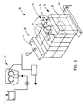
- FIG. 3 shows a diagrammatic view of the device relating to the invention which comprises a drum press 10, after which is fitted the dryer 12 relating to the invention.
- the dryer comprises a feed end 32, which includes a feed trough 34 for feeding pulp into the dryer, a discharge end 30 from which the dried pulp is dropped onto the discharge conveyor 62.
- the actual dryer section is divided into five successive drying segments 64.
- Each drying segment 64 preferably has its own return air system 50 with a fan 52 and a steam radiator 54, although only the return air system of one sector is shown in the figure.
- the figure indicates with broken lines the drying space 20 formed by the cylinders inside the hoods.
- FIG 4 shows a transverse cross-section of a pulp dryer relating to the invention, in which the dryer solution shown in Figure 1 is applied as regards air circulation.
- the dryer solution shown in Figure 1 is applied as regards air circulation.
- several drying gaps 20 similar to a screw conveyor and formed of cylindrical surfaces 16' and 18' are fitted adjacent to each other into the same hood 22.
- space is saved.
- the drying gaps fitted adjacent to each other also gives the drying process flexibility, since it is relatively easy to close one drying gap, e.g. for servicing or any other reason and to bring it into use again when necessary.
- Naturally dryers provided with the type of air circulation shown in Figure 2 can also be fitted adjacent to each other in the same hood.
- the hood can be divided, e.g. by means of a horizontal intermediate wall, into two parts in order to achieve the desired air circulation.
Landscapes
- Engineering & Computer Science (AREA)
- Mechanical Engineering (AREA)
- General Engineering & Computer Science (AREA)
- Drying Of Solid Materials (AREA)
- Paper (AREA)
- Polysaccharides And Polysaccharide Derivatives (AREA)
Claims (25)
- Verfahren zum Trocknen von faserhaltigem Halbstoff, wie beispielsweise chemischer Halbstoff, mechanischer Halbstoff, thermomechanischer Halbstoff, TMP, deinkter Halbstoff oder faserhaltiger Schlamm, wobei bei dem Verfahrender nasse Halbstoff zunächst mechanisch beispielsweise mittels einer Trommel- oder Schraubpresse (10) entwässert wird, wobei danachder Halbstoff durch einen Trockner (12) tritt, bei dem Trocknungsgas durch eine Lage des Halbstoffes geblasen wird, um Wasser aus dem Halbstoff zu verdampfen,
dadurch gekennzeichnet, dassin dem Trockner (12) der Halbstoff durch einen spaltartigen Trocknungsraum (20) tritt, der durch eine erste und eine zweite zylindrische Fläche (16', 18') begrenzt ist, die beide mit Öffnungen (17, 19) versehen sind, wobei der Halbstoff dadurch entlang der ersten oder zweiten Fläche durch eine flügelartige Einrichtung (36) in dem spaltartigen Trocknungsraum (20) nach vorn gedrückt wird. - Verfahren gemäß Anspruch 1,
dadurch gekennzeichnet, dass
der Halbstoff zu einer gasdurchlässigen Halbstofflage an dem Einlass (28) des Trockners ausgebildet wird, wobei die Lage mittels einer Fördereinrichtung (36) in dem Trocknungsraum (20), der zwischen den Flächen (16', 18') ausgebildet ist, von dem Einlass (28) des Trockners zu seinem Auslass (30) nach vorn gefördert wird. - Verfahren gemäß Anspruch 1,
dadurch gekennzeichnet, dass
der Halbstoff zu einer gasdurchlässigen Halbstofflage an dem Einlass (28) des Trockners ausgebildet wird, wobei die Lage mittels einer Fördereinrichtung (36) gestützt durch die erste oder zweite Fläche (16', 18') von dem Einlass (28) des Trockners zu seinem Auslass (30) nach vorn gefördert wird. - Verfahren gemäß Anspruch 1,
dadurch gekennzeichnet, dass
der Halbstoff zu einer mattenartigen Halbstofflage mit hauptsächlich gleichmäßiger Dicke an dem Einlass (28) ausgebildet wird, wobei die Lage von dem ersten Ende der Fläche zu ihrem anderen Ende hin nach vorn gedrückt wird. - Verfahren gemäß Anspruch 1,
dadurch gekennzeichnet, dass
die Halbstofflage in einem Spalt (20) zwischen zwei konzentrischen zylindrischen Flächen, die ineinander sitzen, entlang einer Spiralbahn hauptsächlich von dem ersten Ende der zylindrischen Flächen, das heißt von dem Einlassende zu ihrem anderen Ende, das heißt dem Auslassende, nach vorn gefördert wird. - Verfahren gemäß Anspruch 5,
dadurch gekennzeichnet, dass
der Halbstoff so eingerichtet ist, dass er mehrere Male, üblicherweise 5 bis 25 Mal, um die innere zylindrische Fläche läuft, wenn der Halbstoff von dem Einlassende zu dem Auslassende läuft. - Verfahren gemäß Anspruch 1,
dadurch gekennzeichnet, dass
Trocknungsgas von den Öffnungen (17, 19) der ersten oder zweiten Fläche (16', 18') hauptsächlich senkrecht zu der Halbstofflage hin geblasen wird, die zwischen der ersten und zweiten Fläche läuft. - Verfahren gemäß Anspruch 1,
dadurch gekennzeichnet, dass
Trocknungsgas geblasen wirdin zumindest einem ersten Teil des Trockners aus den Öffnungen (17) der ersten Fläche (16') zu der Halbstofflage hin, die in dem Spalt läuft, undin zumindest einem zweiten Teil des Trockners von den Öffnungen (19), der zweiten Fläche (18') zu der Halbstofflage hin, die in dem Trocknungsraum (20) läuft. - Verfahren gemäß Anspruch 1,
dadurch gekennzeichnet, dass
Trocknungsgas durch die Halbstofflage abwechselnd in eine Richtung und ihre entgegengesetzte Richtung geblasen wird. - Verfahren gemäß Anspruch 1,
dadurch gekennzeichnet, dass
die Trocknungsgasblasströme durch die Halbstofflage erzielt werden, indem ein Druckunterschied, üblicherweise ein Druckunterschied von ungefähr 500 bis 1000 Pa, zwischen dem ersten und dem zweiten Raum (16", 22") eingerichtet wird, die zumindest teilweise durch die Flächen (16', 18') begrenzt sind und die an verschiedenen Seiten der Flächen unter Betrachtung durch den Spalt, der den Trocknungsraum ausbildet, vorhanden sind. - Verfahren gemäß Anspruch 1,
dadurch gekennzeichnet, dass
der Halbstoff zu einer gasdurchlässigen Halbstofflage mit einer Dicke von ungefähr 40 bis 120 mm, vorzugsweise ungefähr 80 mm, in dem Trocknungsraum zwischen der ersten und der zweiten Fläche ausgebildet wird. - Verfahren gemäß Anspruch 1,
dadurch gekennzeichnet, dass
die Halbstofflage in dem Trockner mit einem Trocknungsgas bei einer Temperatur von ungefähr 100 bis 300°C von einem Trockengehalt von ungefähr 30 bis 60% zu einem Trockengehalt von über 80%, typischerweise ungefähr 85 bis 90%, getrocknet wird. - Vorrichtung zum Trocknen von faserhaltigem Halbstoff, wie beispielsweise chemischer Halbstoff, mechanischer Halbstoff, thermomechanischer Halbstoff, TMP, deinkter Halbstoff oder faserhaltiger Schlamm, wobei die Vorrichtung Folgendes aufweist:dadurch gekennzeichnet, dasseine mechanische Entwässerungseinrichtung (10), wie beispielsweise eine Trommel- oder Schraubenpresse zum Entwässern des nassen Halbstoffes, und eingepasst nach der mechanischen Entwässerungseinrichtungeinen Trockner (12), bei dem Wasser von dem Halbstoff verdampft wird, indem Trocknungsgas durch eine Lage des Halbstoffes geblasen wird,
der Trockner (12) Folgendes aufweist:eine erste und eine zweite zylindrische Fläche (16', 18'), die beide mit Öffnungen (17, 19) versehen sind, wobei die Flächen so eingepasst sind, dass sie einen spaltartigen Trocknungsraum (20) zwischen ihnen ausbilden, undeine flügelartige Einrichtung (36) zum Befördern der Halbstofflage nach vorn entlang der ersten oder zweiten Fläche in dem spaltartigen Trocknungsraum (20). - Vorrichtung gemäß Anspruch 13,
dadurch gekennzeichnet, dass
die erste und die zweite Fläche (16', 18') konzentrisch ineinander sitzen, um den spaltartigen Trocknungsraum (20) zwischen ihnen auszubilden. - Vorrichtung gemäß Anspruch 14,
dadurch gekennzeichnet, dassder Trockner aus zwei Zylindern (16, 18), die mit den Flächen ausgerüstet sind, die konzentrisch ineinander sind, wobei das erste Ende der Zylinder mit dem Zuführende (28) des Trockners verbunden ist und das zweite Ende mit dem Ausgabeende (30) des Trockners verbunden ist, und wobei zwischen ihnen der spaltartige Trocknungsraum (20) ausgebildet ist, und aus einer Haube (22), wie beispielsweise ein zylindrisches oder kastenartiges Gehäuse, die den Außenzylinder (18) zumindest teilweise abdeckt, ausgebildet ist, unddie Vorrichtung des Weiteren ein Rückluftsystem (50) aufweist, um das von dem Trockner abgegebene feuchte Gas zu behandeln und um dieses zu dem Trockner als Trocknungsgas zurückkehren zu lassen. - Vorrichtung gemäß Anspruch 15,
dadurch gekennzeichnet, dassder aus Zylindern und einer Haube ausgebildete Trockner in aufeinanderfolgende Segmente, beispielsweise in ungefähr 5 Segmente (64) geteilt ist undzumindest zwei der Segmente ein Rückluftsystem (50) haben, das zumindest teilweise separat ist. - Vorrichtung gemäß Anspruch 15,
dadurch gekennzeichnet, dassdie Haube (22) oder ein Teil der Haube mittels Zwischenwänden (44), die hauptsächlich in der Längsrichtung der Zylinder sitzen, in zwei oder mehr Teile (46, 48) geteilt ist undsie eine Einrichtung (52, 17, 19) zum Blasen von Trocknungsgas durch die Halbstofflage, die getrocknet wird, aufweist, wobei die Einrichtung bewirktin dem ersten Teil des Trockners die Strömung des Trocknungsgases von dem inneren Zylinder durch die Halbstofflage zu dem ersten Haubenteil (46) undin dem zweiten Teil des Trockners die Strömung des Trocknungsgases von dem zweiten Teil (48) der Haube durch die Halbstofflage zu dem inneren Zylinder. - Vorrichtung gemäß Anspruch 17,
dadurch gekennzeichnet, dass
ein Unterdruck in dem ersten Haubenteil (46) und ein Überdruck in dem zweiten Haubenteil (48) im Vergleich zu dem Druck vorhanden ist, der in dem inneren Zylinder (16) vorherrscht. - Vorrichtung gemäß Anspruch 13,
dadurch gekennzeichnet, dass
der Trockner aus Folgendem besteht:einer Vorrichtung ähnlich einem Schraubenförderer miteiner perforierten inneren Röhre (16), die die erste Fläche vorsieht,einem perforierten äußeren Gehäuse (18'), das die zweite Fläche vorsieht,einer geschlossenen Haube (22), die das perforierte äußere Gehäuse der Vorrichtung, die ähnlich einem Schraubenförderer ist, abdeckt undeiner Einrichtung zum Fördern von Trocknungsgas in zumindest einem Teil der Vorrichtung, die ähnlich einem Schraubenförderer ist, von der perforierten inneren Röhre (16) durch die Halbstofflage, die in dem spaltartigen Trocknungsraum nach vorn drückt, und durch das perforierte äußere Gehäuse in die geschlossene Haube. - Vorrichtung gemäß Anspruch 19,
dadurch gekennzeichnet, dass
der Trockner des Weiteren Folgendes aufweist:eine zweite Einrichtung zum Fördern von Trocknungsgas in zumindest einem zweiten Teil der Vorrichtung, die ähnlich einem Schraubenförderer ist, von der geschlossenen Haube durch das perforierte äußere Gehäuse (18'), wobei die Halbstofflage in dem spaltartigen Trocknungsraum (20) und der Wand der perforierten inneren Röhre innerhalb der inneren Röhre (16) nach vorn drückt. - Vorrichtung gemäß Anspruch 15,
dadurch gekennzeichnet, dassder innere Zylinder (16) ein sich drehender Zylinder ist unddie eine oder mehreren flügelartigen Einrichtungen (36) spiralartig um das Gehäuse des inneren Zylinders eingepasst sind. - Vorrichtung gemäß Anspruch 13,
dadurch gekennzeichnet, dass
der Abstand zwischen der ersten und der zweiten Fläche, die den spaltartigen Trocknungsraum ausbilden, ungefähr 40 bis 120 mm, typischerweise ungefähr 80 mm, beträgt. - Vorrichtung gemäß Anspruch 14 oder 15,
dadurch gekennzeichnet, dass
der Durchmesser der inneren zylindrischen Fläche oder des inneren Zylinders ungefähr 2 bis 5 m beträgt. - Vorrichtung gemäß Anspruch 14,
dadurch gekennzeichnet, dass
der Einlass (34) für den zu trocknenden Halbstoff an dem ersten Ende der zylindrischen Flächen (16', 18') angeordnet ist und der Auslass (38) für den getrockneten Halbstoff an dem anderen Ende dieser Flächen angeordnet ist. - Vorrichtung gemäß Anspruch 13,
dadurch gekennzeichnet, dass
zwischen der mechanischen Entwässerungseinrichtung (10) und dem Trockner (12) ein mechanischer Halbstoffzerfaserer, wie beispielsweise eine Feinpulverisiereinrichtung, sitzt, durch den die Fasern voneinander vor dem Trocknen getrennt werden.
Applications Claiming Priority (3)
| Application Number | Priority Date | Filing Date | Title |
|---|---|---|---|
| FI981523 | 1998-07-02 | ||
| FI981523A FI104444B (fi) | 1998-07-02 | 1998-07-02 | Menetelmä ja laite sellun kuivattamiseksi |
| PCT/FI1999/000541 WO2000001994A1 (en) | 1998-07-02 | 1999-06-21 | Method and apparatus for drying pulp |
Publications (2)
| Publication Number | Publication Date |
|---|---|
| EP1110047A1 EP1110047A1 (de) | 2001-06-27 |
| EP1110047B1 true EP1110047B1 (de) | 2003-07-30 |
Family
ID=8552120
Family Applications (1)
| Application Number | Title | Priority Date | Filing Date |
|---|---|---|---|
| EP99931314A Expired - Lifetime EP1110047B1 (de) | 1998-07-02 | 1999-06-21 | Verfahren und vorrichtung zur trocknung von breiartigen substanzen |
Country Status (9)
| Country | Link |
|---|---|
| US (1) | US6393728B1 (de) |
| EP (1) | EP1110047B1 (de) |
| AT (1) | ATE246329T1 (de) |
| AU (1) | AU4786599A (de) |
| CA (1) | CA2336480C (de) |
| DE (1) | DE69910044T2 (de) |
| ES (1) | ES2201733T3 (de) |
| FI (1) | FI104444B (de) |
| WO (1) | WO2000001994A1 (de) |
Cited By (2)
| Publication number | Priority date | Publication date | Assignee | Title |
|---|---|---|---|---|
| WO2007134656A1 (de) | 2006-05-22 | 2007-11-29 | Ijzerlo Holding B.V. | Trockner für schüttfähiges trocknungsgut und verfahren zum betreiben eines trockners |
| CN101906673A (zh) * | 2010-07-09 | 2010-12-08 | 中钢集团洛阳耐火材料研究院有限公司 | 一种纤维制品的干燥窑 |
Families Citing this family (5)
| Publication number | Priority date | Publication date | Assignee | Title |
|---|---|---|---|---|
| US20060201641A1 (en) * | 2001-08-07 | 2006-09-14 | Bioregional Minimills (Uk) Limited | Methods for producing pulp and treating black liquor |
| DE10143004A1 (de) * | 2001-09-03 | 2003-03-20 | Christian Widmer | Presse zur Entfeuchtung von Feuchtgut, insbesondere Restmüll |
| BRPI0701974B1 (pt) * | 2007-06-19 | 2018-11-13 | Fraza Carlos | aperfeiçoamento introduzido em processo de secagem de bagaço de cana triturado ou outros para posterior trabalho de briquetagem ou outros |
| FR3030559B1 (fr) * | 2014-12-23 | 2018-08-17 | E.T.I.A. - Evaluation Technologique, Ingenierie Et Applications. | Dispositif de traitement gaz/solide par un reacteur a vis comprenant une brosse rapportee sur la vis |
| CN107560396A (zh) * | 2017-09-27 | 2018-01-09 | 芜湖凯奥尔环保科技有限公司 | 一种植物纤维烘干用卷筒烘干机 |
Family Cites Families (10)
| Publication number | Priority date | Publication date | Assignee | Title |
|---|---|---|---|---|
| US3478679A (en) * | 1967-05-24 | 1969-11-18 | Stearns Roger Corp | Pulp deliquifying press |
| FI58020C (fi) * | 1976-02-09 | 1980-11-10 | Ahlstroem Oy | Foerfarande och anordning foer torkning av ett cellulosahaltigt fibermaterial |
| US4112578A (en) | 1977-07-08 | 1978-09-12 | Curfman, Brainerd, Harris, Bell, Weigans And Depew | Apparatus for disassembling pallets |
| AT381718B (de) | 1982-01-20 | 1986-11-25 | Voest Alpine Ag | Rotierendes spaltsieb zum trocknen von feststoffen, z.b. braunkohlen |
| US4492478A (en) * | 1981-09-18 | 1985-01-08 | Yasuro Ito | Method and apparatus for applying mortar or concrete |
| US5263267A (en) * | 1989-03-20 | 1993-11-23 | Judco Manufacturing, Inc. | Method and apparatus for reducing volatile content of sewage sludge and other feed materials |
| EP0671503A3 (de) | 1994-03-10 | 1999-01-20 | Mc'enman S.L. | Vorrichtung und Verfahren zum Entfeuchten von Zellstoff-Produkten durch intensive Verdampfung |
| US5562832A (en) * | 1995-01-13 | 1996-10-08 | Beloit Technologies, Inc. | Absorptive sludge dewatering process for papermaking waste |
| US5879566A (en) * | 1997-02-03 | 1999-03-09 | The Scientific Ecology Group, Inc. | Integrated steam reforming operation for processing organic contaminated sludges and system |
| US6256902B1 (en) * | 1998-11-03 | 2001-07-10 | John R. Flaherty | Apparatus and method for desiccating and deagglomerating wet, particulate materials |
-
1998
- 1998-07-02 FI FI981523A patent/FI104444B/fi active
-
1999
- 1999-06-21 US US09/719,092 patent/US6393728B1/en not_active Expired - Fee Related
- 1999-06-21 DE DE69910044T patent/DE69910044T2/de not_active Expired - Fee Related
- 1999-06-21 AT AT99931314T patent/ATE246329T1/de not_active IP Right Cessation
- 1999-06-21 AU AU47865/99A patent/AU4786599A/en not_active Abandoned
- 1999-06-21 CA CA002336480A patent/CA2336480C/en not_active Expired - Fee Related
- 1999-06-21 ES ES99931314T patent/ES2201733T3/es not_active Expired - Lifetime
- 1999-06-21 EP EP99931314A patent/EP1110047B1/de not_active Expired - Lifetime
- 1999-06-21 WO PCT/FI1999/000541 patent/WO2000001994A1/en not_active Ceased
Cited By (2)
| Publication number | Priority date | Publication date | Assignee | Title |
|---|---|---|---|---|
| WO2007134656A1 (de) | 2006-05-22 | 2007-11-29 | Ijzerlo Holding B.V. | Trockner für schüttfähiges trocknungsgut und verfahren zum betreiben eines trockners |
| CN101906673A (zh) * | 2010-07-09 | 2010-12-08 | 中钢集团洛阳耐火材料研究院有限公司 | 一种纤维制品的干燥窑 |
Also Published As
| Publication number | Publication date |
|---|---|
| AU4786599A (en) | 2000-01-24 |
| CA2336480A1 (en) | 2000-01-13 |
| ATE246329T1 (de) | 2003-08-15 |
| CA2336480C (en) | 2005-04-12 |
| EP1110047A1 (de) | 2001-06-27 |
| US6393728B1 (en) | 2002-05-28 |
| FI981523A0 (fi) | 1998-07-02 |
| ES2201733T3 (es) | 2004-03-16 |
| FI104444B (fi) | 2000-01-31 |
| DE69910044D1 (de) | 2003-09-04 |
| DE69910044T2 (de) | 2004-04-01 |
| WO2000001994A1 (en) | 2000-01-13 |
Similar Documents
| Publication | Publication Date | Title |
|---|---|---|
| US6207020B1 (en) | Method for conditioning paper and paperboard webs | |
| JP4008026B2 (ja) | 高真空によって通過する熱気を用いてセルロース材料シートを脱水する方法、この方法の実施装置および得られる製品 | |
| FI91293C (fi) | Palokaasuilla kuumennettu sylinterikuivaaja | |
| US6393728B1 (en) | Method and apparatus for drying pulp | |
| FI104276B (fi) | Kuivatusosakonsepti ja menetelmä paperirainan/kartonkirainan kuivatuksessa | |
| EP0922138B1 (de) | Verfahren zum erhöhen der betriebsgeschwindigkeit einer papiermaschine mit einer zweireihigen trockenpartie | |
| US3639207A (en) | Method for drying nonwoven fabric | |
| EP1075565B1 (de) | Halbstofftrocknungslinie und verfahren zum trocknen von halbstoff | |
| CA2211171C (en) | Papermaking dryer with multi-roll vacuum chamber | |
| WO2020005236A1 (en) | Through-air drying apparatus and methods of manufacture | |
| EP1320642B1 (de) | Verfahren zum trocknen einer materialbahn | |
| US3283415A (en) | Paper drying apparatus | |
| CA1131441A (en) | Method and device for flake-dryng of cellulose pulp | |
| AU2001292714A1 (en) | Method of drying a web | |
| EP1125018B1 (de) | Verfahren und trockenpartie zur entwässerung einer faserbahn | |
| US7090746B2 (en) | Process and device for removing water from a mechanical pulp, chemical pulp or paper sheet | |
| FI87668C (fi) | Foerfarande och anordning foer behandling av en banformig produkt | |
| US3269029A (en) | Jet spiral drier | |
| SU1118837A1 (ru) | Сушилка дл сыпучих материалов | |
| CA1057010A (en) | Process and apparatus for flash drying cellulose pulp | |
| KR810000766B1 (ko) | 제지기의 중공 원통형 건조드럼 | |
| SU785616A1 (ru) | Сушилка | |
| SU1216597A1 (ru) | Установка дл сушки травы | |
| SU1368352A1 (ru) | Вентил ционный колпак сушильной части бумагоделательной машины | |
| WO2001003804A1 (en) | Method and device for separating fiber from a flow of steam |
Legal Events
| Date | Code | Title | Description |
|---|---|---|---|
| PUAI | Public reference made under article 153(3) epc to a published international application that has entered the european phase |
Free format text: ORIGINAL CODE: 0009012 |
|
| 17P | Request for examination filed |
Effective date: 20010109 |
|
| AK | Designated contracting states |
Kind code of ref document: A1 Designated state(s): AT DE ES FR GB SE |
|
| RAP1 | Party data changed (applicant data changed or rights of an application transferred) |
Owner name: METSO PAPER, INC. |
|
| GRAH | Despatch of communication of intention to grant a patent |
Free format text: ORIGINAL CODE: EPIDOS IGRA |
|
| GRAH | Despatch of communication of intention to grant a patent |
Free format text: ORIGINAL CODE: EPIDOS IGRA |
|
| GRAA | (expected) grant |
Free format text: ORIGINAL CODE: 0009210 |
|
| RIN1 | Information on inventor provided before grant (corrected) |
Inventor name: HUHTALA, OLLI Inventor name: SAIRANEN, PAAVO |
|
| AK | Designated contracting states |
Designated state(s): AT DE ES FR GB SE |
|
| REG | Reference to a national code |
Ref country code: GB Ref legal event code: FG4D |
|
| REF | Corresponds to: |
Ref document number: 69910044 Country of ref document: DE Date of ref document: 20030904 Kind code of ref document: P |
|
| REG | Reference to a national code |
Ref country code: SE Ref legal event code: TRGR |
|
| REG | Reference to a national code |
Ref country code: ES Ref legal event code: FG2A Ref document number: 2201733 Country of ref document: ES Kind code of ref document: T3 |
|
| ET | Fr: translation filed | ||
| PLBE | No opposition filed within time limit |
Free format text: ORIGINAL CODE: 0009261 |
|
| STAA | Information on the status of an ep patent application or granted ep patent |
Free format text: STATUS: NO OPPOSITION FILED WITHIN TIME LIMIT |
|
| 26N | No opposition filed |
Effective date: 20040504 |
|
| ET1 | Fr: translation filed ** revision of the translation of the patent or the claims | ||
| PGFP | Annual fee paid to national office [announced via postgrant information from national office to epo] |
Ref country code: SE Payment date: 20070614 Year of fee payment: 9 |
|
| PGFP | Annual fee paid to national office [announced via postgrant information from national office to epo] |
Ref country code: AT Payment date: 20070618 Year of fee payment: 9 |
|
| PGFP | Annual fee paid to national office [announced via postgrant information from national office to epo] |
Ref country code: DE Payment date: 20070622 Year of fee payment: 9 |
|
| PGFP | Annual fee paid to national office [announced via postgrant information from national office to epo] |
Ref country code: ES Payment date: 20070628 Year of fee payment: 9 |
|
| PGFP | Annual fee paid to national office [announced via postgrant information from national office to epo] |
Ref country code: GB Payment date: 20070621 Year of fee payment: 9 |
|
| PGFP | Annual fee paid to national office [announced via postgrant information from national office to epo] |
Ref country code: FR Payment date: 20070615 Year of fee payment: 9 |
|
| EUG | Se: european patent has lapsed | ||
| GBPC | Gb: european patent ceased through non-payment of renewal fee |
Effective date: 20080621 |
|
| REG | Reference to a national code |
Ref country code: FR Ref legal event code: ST Effective date: 20090228 |
|
| PG25 | Lapsed in a contracting state [announced via postgrant information from national office to epo] |
Ref country code: DE Free format text: LAPSE BECAUSE OF NON-PAYMENT OF DUE FEES Effective date: 20090101 Ref country code: AT Free format text: LAPSE BECAUSE OF NON-PAYMENT OF DUE FEES Effective date: 20080621 |
|
| PG25 | Lapsed in a contracting state [announced via postgrant information from national office to epo] |
Ref country code: GB Free format text: LAPSE BECAUSE OF NON-PAYMENT OF DUE FEES Effective date: 20080621 |
|
| REG | Reference to a national code |
Ref country code: ES Ref legal event code: FD2A Effective date: 20080623 |
|
| PG25 | Lapsed in a contracting state [announced via postgrant information from national office to epo] |
Ref country code: FR Free format text: LAPSE BECAUSE OF NON-PAYMENT OF DUE FEES Effective date: 20080630 |
|
| PG25 | Lapsed in a contracting state [announced via postgrant information from national office to epo] |
Ref country code: ES Free format text: LAPSE BECAUSE OF NON-PAYMENT OF DUE FEES Effective date: 20080623 |
|
| PG25 | Lapsed in a contracting state [announced via postgrant information from national office to epo] |
Ref country code: SE Free format text: LAPSE BECAUSE OF NON-PAYMENT OF DUE FEES Effective date: 20080622 |